Publisher’s version / Version de l'éditeur:
ACS Omega, 3, 9, pp. 11684-11690, 2018-09-24
READ THESE TERMS AND CONDITIONS CAREFULLY BEFORE USING THIS WEBSITE.
https://nrc-publications.canada.ca/eng/copyright
Vous avez des questions? Nous pouvons vous aider. Pour communiquer directement avec un auteur, consultez la première page de la revue dans laquelle son article a été publié afin de trouver ses coordonnées. Si vous n’arrivez pas à les repérer, communiquez avec nous à [email protected].
Questions? Contact the NRC Publications Archive team at
[email protected]. If you wish to email the authors directly, please see the first page of the publication for their contact information.
NRC Publications Archive
Archives des publications du CNRC
This publication could be one of several versions: author’s original, accepted manuscript or the publisher’s version. / La version de cette publication peut être l’une des suivantes : la version prépublication de l’auteur, la version acceptée du manuscrit ou la version de l’éditeur.
For the publisher’s version, please access the DOI link below./ Pour consulter la version de l’éditeur, utilisez le lien DOI ci-dessous.
https://doi.org/10.1021/acsomega.8b01388
Access and use of this website and the material on it are subject to the Terms and Conditions set forth at
Revealing the role of poly(vinylidene fluoride) binder in Si/graphite
composite anode for Li-ion batteries
Zhao, Xiuyun; Niketic, Svetlana; Yim, Chae-Ho; Zhou, Jigang; Wang, Jian;
Abu-Lebdeh, Yaser
https://publications-cnrc.canada.ca/fra/droits
L’accès à ce site Web et l’utilisation de son contenu sont assujettis aux conditions présentées dans le site LISEZ CES CONDITIONS ATTENTIVEMENT AVANT D’UTILISER CE SITE WEB.
NRC Publications Record / Notice d'Archives des publications de CNRC:
https://nrc-publications.canada.ca/eng/view/object/?id=d830f21c-648b-4fac-ad97-8398acc70090 https://publications-cnrc.canada.ca/fra/voir/objet/?id=d830f21c-648b-4fac-ad97-8398acc70090Revealing the Role of Poly(vinylidene fluoride) Binder in Si/Graphite
Composite Anode for Li-Ion Batteries
Xiuyun Zhao,
†Svetlana Niketic,
†Chae-Ho Yim,
†Jigang Zhou,
‡Jian Wang,
‡and Yaser Abu-Lebdeh
*
,††
National Research Council Canada, 1200 Montreal Road, Ottawa, Ontario K1A 0R6, Canada ‡
Canadian Light Source Incorporation, Saskatoon S7N 2V3, Canada
*
S Supporting InformationABSTRACT: The conventional polyvinylidene fluoride (PVDF) binder works well with the graphite anode, but when combined with silicon in composites to increase the energy density of Li-ion batteries, it results in severe capacity fade. Herein, by using scanning electron microscopy and energy-dispersive X-ray spectroscopy analyses, we reveal that this failure stems from the loss of connectivity between the silicon (or its agglomerates), graphite, and PVDF binder because of the mechanical stresses experienced during battery cycling. More importantly, we reveal for the first time that the PVDF binder undergoes chemical decomposition during the cycling of not only the composite but also the Si-only or even graphite-only electrodes despite the excellent battery performance of the latter. Through X-ray photoemission electron microscopy and X-ray photoelectron spectroscopy techniques, LiF was identified as the predominant decomposition product. We show that the distribution of LiF in the electrodes due to the differences in the interactions between PVDF and either Si or graphite could correlate with the performance of the battery. This study shows that the most suitable binder for the composite electrode is a polymer with a good chemical interaction with both graphite and silicon.
1. INTRODUCTION
Recently, there is a great interest in combining graphite with silicon as an anode material for lithium-ion batteries to increase their practical energy density for the next-generation consumer electronics, electric vehicles, and energy storage for the grid.1−4 The focus is on composites with low silicon content (<25 wt %) to design a graphite-rich composite electrode that is compatible with the current manufacturing processes and can lead to incremental improvement in the practical energy density of full Li-ion batteries eventually reaching a maximum of 17%.1
It is well-known that the binders play an essential role in the mechanical stabilization of electrodes. Polyvinylidene fluoride (PVDF) is still one of the most popular binders for graphite electrode in the industry, but it is not effective for Si electrodes. A number of alternative binders have been investigated in the literature for Si-based negative electrodes, and stable cycling could be obtained by using the polyimide binder or water-based binders water-based on poly(carboxylic acid)s and their alkali metal salts, such as carboxymethyl cellulose, poly(acrylic acid)
(PAA), and alginate.5 However, these binders are not perfect for Si/graphite composite electrodes, and to the best of our knowledge, very few binders have been designed specifically for Si/graphite composite electrodes. During our search for the ideal binders, we have been intrigued by the finding that the graphite-rich Si/graphite composite electrode with PVDF binder loses its capacity very quickly during cycling, and after five cycles, the capacity is even lower than that of the graphite-only electrode.6 We essentially want to address the question “How could a small amount of silicon cause such a catastrophic effect on a composite that is very rich in graphite which is known for its good affinity to PVDF?”
Previous studies focused on the role of silicon7in electrode morphology and mechanical stability8with the LiPAA binder and/or the LiPF6-based electrolytes. Bareño et al. have found that the erosion of Si particles by hydrofluoric acid produced
Received: July 4, 2018 Accepted: September 10, 2018 Published: September 24, 2018
Article http://pubs.acs.org/journal/acsodf
Cite This:ACS Omega2018, 3, 11684−11690
This is an open access article published under a Creative Commons Non-Commercial No Derivative Works (CC-BY-NC-ND) Attribution License, which permits copying and redistribution of the article, and creation of adaptations, all for non-commercial purposes.
from LiPF6hydrolysis is a leading cause for the deterioration of the electrochemical performance of silicon-containing electro-des as well as the silica deposited on the positive side.7 However, to the best of our knowledge, very little research has focused on the failure analysis of graphite-rich Si/graphite composite electrode with the PVDF binder. Gómez-Cámer et al. prepared 4.75% Si/90 wt % graphite composite electrodes with a 4 wt % PVDF binder and studied the electrode layer expansion by electrochemical in situ dilatometry.8They found that the charge capacity dropped to the value corresponding to the graphite contribution for the electrodes made with KS6, whereas for SLP30 graphite-containing electrodes the charge capacity faded even below the expected value for the amount of graphite present in the electrode. They suggest that the SLP30 graphite-containing electrodes besides the Si particles become partially electrochemically inactive because of their microstructure. The SLP30 graphite flakes are mostly aligned in parallel to the current collector, and a larger number of graphite platelets are connected through plane-to-plane contacts to the current collector. Thus, the electric conductive network in the SLP30 electrodes is easy to be disrupted by the expanding Si nanoparticles with more and more graphite contacts being interrupted.8However, the role of PVDF binder in the failure mechanism could not be clearly identified because of the presence of another fluorine-containing species such as the LiPF6salt in the Li-ion cells.
In this work, we have used a nonfluorinated salt, LiClO4, in the electrolyte, so PVDF is the only source of fluorine in the cells. We have prepared a graphite-rich Si/graphite composite electrode (20 wt % Si, 65 wt % graphite) with the PVDF binder and have investigated the electrode failure and the effect of binder decomposition on the electrochemical performance using a nonfluorinated salt, LiClO4, in nonaqueous electrolyte solution. Electrochemical test, scanning electron microscopy (SEM), energy-dispersive X-ray spectroscopy (EDXS), X-ray photoelectron spectroscopy (XPS), and X-ray photoemission electron microscopy (X-PEEM) are carried out to analyze the origin of electrode failure and the change in binder
composition during battery cycling. The results provide a useful guide to the design of better binders for a graphite-rich Si/graphite composite electrode system.
2. RESULTS AND DISCUSSION
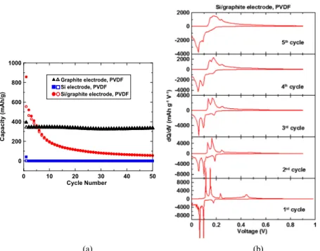
Figure 1a shows the cycling performance of Li-ion cells made with the graphite-only electrode, Si-only electrode, and Si/ graphite composite electrode using the PVDF binder. The graphite-only electrode shows a first discharge capacity of about 394 mA h/g and a first reversible capacity of 350 mA h/ g corresponding to the electrochemical intercalation reaction 6C + Li++ e−
→ LiC6with a theoretical capacity of 372 mA h/ g. After the initial solid electrolyte interphase (SEI) formation, the graphite-only electrode has a good capacity retention during the following 50 cycles with a stable capacity of ∼350 mA h/g. The Si-only electrode shows an extremely low first discharge capacity of 40 mA h/g and nearly no initial reversible capacity. At room temperature, in theory, silicon can alloy electrochemically with lithium following the reaction Si + 3.75Li++ 3.75e−
→ Li3.75Si with a theoretical capacity of 3578 mA h/g.5 Experimentally, it still shows a substantial capacity when other binders such as lithium salt of PAA (LiPAA) are used as shown inFigure S1. It delivers a first discharge capacity of about 2125 mA h/g and a first reversible capacity of 1133 mA h/g, and after 50 cycles, it can still retain a capacity of ∼400 mA h/g. This proves that the failure in the case of PVDF is not due to silicon and points the finger toward PVDF. The Si/graphite composite electrode shows a discharge capacity of ∼858 mA h/g and a charge capacity of ∼554 mA h/g in the first cycle with an initial Coulombic efficiency of 64.6%. Intriguingly, this graphite-rich composite electrode starts to show a lower capacity than that of the graphite electrode beyond the fifth cycle. A charge capacity of only 55 mA h/g can be observed in the 50th cycle.
The differential capacity curves of the Si/graphite composite electrode were plotted for the first five cycles and are shown in
Figure 1b. In the first cycle, the electrode shows the characteristic profile of graphite, as well as a broad peak at
Figure 1.(a) Cycling performance of the graphite-only electrode, Si-only electrode, and Si/graphite composite electrode with the PVDF binder. (b) Differential capacity curves of the Si/graphite composite electrode with the PVDF binder in the first five cycles.
ACS Omega Article
DOI:10.1021/acsomega.8b01388
ACS Omega2018, 3, 11684−11690
about 0.44 V, indicating the formation of the Li15Si4 phase.5 From the second cycle onward, the 0.44 V peak disappears, and the graphite features dominate the profile, indicating that the Si nanoparticles become electrochemically inactive. In the following four cycles, all the graphite peaks become broader, and the anodic peaks shift to a higher potential progressively showing electrode polarization and impedance increase. Beyond the fifth cycle, the characteristic features of the graphite electrode almost disappear, and the residual capacity is likely to originate from lithium ion adsorption/desorption at the electrode surface similar to the case of conversion-type electrodes.9 This indicates that the graphite in the composite electrode loses its electrochemical reactivity to lithium.
In order to elucidate the failure mechanism, the electrodes were recovered from the cells after five cycles and were analyzed and compared with the uncycled electrodes by the SEM and EDXS analysis. Figure 2a,d,g and b,e,h shows the SEM images of the cycled Si/graphite composite electrode, Si-only electrode, and graphite-Si-only electrode with the PVDF binder and the corresponding EDXS maps of fluorine element
distribution, respectively. For the Si/graphite electrode, there are no significant changes in the electrode morphology of a low-magnification SEM image compared to that before cycling. The cycled electrode still has a uniform surface, and the dispersion of nanosilicon particles and carbon black particles in the composite seems uniform, which was also confirmed by the EDXS analysis shown in Figures S2 and S3. In a higher magnification image shown inFigure 2a, it can be seen that the silicon particles are still connected with carbon black particles by the PVDF binder. However, these Si nanoparticles have a rougher surface because of the pulverization during cycling. In addition, they have agglomerated into bigger particles, and there are gaps between these bigger particles. Finally, naked graphite chunks can be seen in some regions, and most of the PVDF binder resides with silicon. This was confirmed by the EDXS map of the F shown inFigure 2b. Correspondingly, the gaps can be observed between these naked graphite and the agglomerated silicon particles. This could be caused by the volume expansion and contraction of silicon particles which were connected with the graphite by the PVDF binder and
Figure 2. (a,d,g) SEM images of the cycled Si/graphite composite electrode, Si electrode, and graphite electrode, respectively; (b,e,h) corresponding EDXS mappings of the F element; and (c,f,i) XPS spectra of F 1s for the corresponding electrodes before and after cycling.
carbon black particles before cycling. As a result, the capacity loss of silicon is likely to originate from the electrical conductivity loss caused by pulverization and subsequent agglomeration of the particles, whereas the capacity loss of graphite is likely to originate from the electrical conductivity loss caused by the separation between the graphite electrode and the PVDF binder and carbon black. Both of them contribute to the loss of electrochemical activity of the Si/ graphite composite electrode.
For the Si-only electrode before cycling, the PVDF was uniformly mixed with silicon and carbon black as the EDXS map of F shows a very uniform distribution, as shown inFigure S4, and some cracks can be clearly seen before cycling. After cycling, it is also very clear that most silicon particles have a much rougher surface compared to that before cycling, and these cycled silicon particles and carbon black particles agglomerate together as shown in Figures 2d and S5. Also, the PVDF binder distribution is not as good as before cycling as the EDXS map of F element shows that F is concentrated on big Si particles after cycling (Figure 2e). This is why the Si-only electrode with the PVDF binder shown inFigure 1could not deliver the initial reversible capacity. For the graphite-only electrode, the PVDF binder adheres to each graphite chunk by carbon black particles before cycling, as shown inFigure S6. After cycling, some uniform spots can be seen on the electrode surface, and the F element is concentrated on these spots, as shown inFigure 2g,h. This is very interesting as it looks like some PVDF decomposition also occurred during the cycling in a graphite-only electrode.
In order to further understand the capacity loss of graphite in the Si/composite electrode, XPS was carried out to analyze
the composition change of the electrode surface. Figure 2c shows the XPS spectra of F 1s for the Si/graphite composite electrode. Before cycling, there is only one peak at 687 eV related to the C−F bonds (CF2 in the PVDF binder). After cycling, the F 1s peak becomes broader and comprises two components at 684.7 and 687 eV, associated with LiF and C− F bonds of the PVDF binder, respectively. The presence of LiF component at the surface indicates that during cycling, Li reacts directly with the PVDF binder, which is the only source of fluorine in the whole system. Interestingly, similar XPS results were observed for the Si-only and graphite-only electrodes, as shown in Figure 2f,i. This suggests that it is not very clear whether the chemical decomposition of the PVDF binder is the main cause of the poor electrochemical properties of the Si/graphite composite electrode and the Si-only electrode and, if so, by how much. This is not consistent with the conventional view in which a decomposed binder can no longer perform its function to hold the electrode assembly by binding all of its components together and also adhering them to the current collector.10 However, Kim et al. have
indicated that PVDF decomposition might take place at a potential higher than 1 V when half cells were tested with more than 50% PVDF was used with synthetic graphite.11 Herein, we confirm that this is a general phenomenon for PVDF that can also take place at even small amounts of PVDF and irrespective of the active material, and the decomposition product is mainly LiF.
As XPS indicates that the chemical decomposition of the PVDF binder into LiF occurs during the cycling of all the three electrodes, the X-PEEM measurement was performed to further disclose the distribution of LiF throughout the
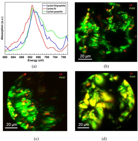
Figure 3.(a) Fluorine K-edge XANES spectra of the Si/graphite electrode before cycling. (b) Standard fluorine K-edge XANES spectra of PVDF and LiF. (c) Fluorine chemical mapping out of fitting F K-edge image stack of the electrode.
ACS Omega Article
DOI:10.1021/acsomega.8b01388
ACS Omega2018, 3, 11684−11690
electrodes. The F K-edge X-ray absorption near-edge structure (XANES) spectra and chemical mapping of various F species in the Si/graphite electrode before cycling are shown inFigure 3. The two fitting spectra were extracted from the two regions with distinct morphological features: region 1 has dominant small particles, whereas region 2 is dominated with large particles. Spectrum 1 and spectrum 2 shown inFigure 3a are corresponding to these two regions, respectively. As for the electrode before cycling, it is clear that there is no LiF in the composition. Compared to the fluorine reference spectra in PVDF and in LiF shown inFigure 3b, the spectroscopic profile in spectrum 2 likely corresponds to PVDF, whereas the sharp peak at 693 eV in spectrum 1 may be due to the formation of some fluorine-containing species, such as F−O or F−Si, during the electrode drying process. The existence of LiF in region 1 is spectroscopically excluded because of the absence of the characteristic peak at ∼703 eV. The distribution of these two types of species, PVDF (green) and the reacted PVDF (red), was mapped out by fitting the F K-edge image stack of the electrode as shown inFigure 3c.
Figure 4 shows the F K-edge XANES spectra (Figure 4a) and the fluorine chemical mappings of the cycled Si/graphite electrode (Figure 4b), Si-only electrode (Figure 4c), and graphite-only electrode (Figure 4d). The distribution of PVDF and LiF in these chemical mappings was obtained through fitting F K-edge spectra image stacks by using the reference spectra of PVDF and LiF. The appearance of the sharp peak at ∼693 eV and the broad peak at ∼703 eV in the F K-edge spectra from all the three electrodes suggests the formation of LiF after cycling.12The signal-to-noise ratio decreases from the graphite-only to the Si/graphite composite and to the Si-only
composite, which could imply a similar decrease in the total amount of F in the electrodes. Furthermore, the LiF and PVDF distribution in those electrodes was exhibited as a repulsive guidance molecule mapping, which shows the existence of LiF-rich hot spots in the Si/graphite and Si-only electrodes, whereas a more uniform coexistence dispersion in the cycled graphite-only electrode. Combined with the EDXS mapping of the cycled graphite-only electrode shown in Figure 2i, it is suspected that the uniform decomposition of PVDF is partly responsible for good electrochemical performance of the graphite-only electrode. On the basis of this finding, we hypothesize that LiF that forms part of the SEI in conventional electrolytes does not only originate from the LiPF6salt but also from the PVDF binder. The electrochemical decomposition of PVDF generates fluoride ion species that react chemically with lithium ions and form LiF. A similar behavior was reported in the case of sodium-ion cells.10 It was shown that in the presence of additives such as fluoroethylene carbonate, the decomposition of PVDF could suppress this process by releasing the fluoride ions that can compete for the ions (sodium or Li), which might explain why graphite electrodes maintain their integrity during cycling and retain a good battery performance.
3. CONCLUSIONS
To conclude, we investigated the failure mechanism of the graphite-rich Si/graphite composite electrode with the PVDF binder in Li-ion half-cell. We revealed that it could be attributed to two reasons: one is silicon inactivity caused by the pulverization and agglomeration of silicon particles because of the large volume change during cycling that takes place right
Figure 4.(a) Fluorine K-edge XANES spectra and corresponding fluorine chemical mappings of (b) cycled Si/graphite, (c) cycled Si, and (d) cycled graphite electrodes.
after the first cycle. The other one is graphite inactivity where some graphite particles lose their connection with carbon black and PVDF binder that is caused by the expansion and contraction of neighboring silicon particles. Moreover, it was demonstrated that the PVDF binder decomposes to form LiF at the surface of the electrodes during cycling in the fluorine-free electrolyte in both single electrode (Si-only or graphite-only) and the Si/graphite composite electrode with no impact on the battery performance in the case of graphite. However, it is still not very clear how this binder decomposition affects the battery performance, but it can be concluded that an appropriate binder for any Si/graphite composite even with the smallest amount of silicon should have a strong interaction/adhesion to both silicon and graphite surfaces.
4. EXPERIMENTAL SECTION
4.1. Electrode Preparation. The graphite electrode was made by mixing the graphite powder (MAG-D, Hitachi), Super P carbon black (Timical Carbon, Belgium), and PVDF (HSV 900 Kynar) binder in a 90:2:8 mass ratio. An appropriate N-methyl-2-pyrrolidone (NMP, Sigma-Aldrich, anhydrous 99.5%) was used to form the slurry. The silicon electrode was made by combining nanosilicon powder (<100 nm, Aldrich), carbon black and LiPAA binder (LiPAA), or PVDF binder in an 85:5:10 mass ratio. Distilled water and isopropanol were added to form the slurry in the LiPAA case; NMP was added in the PVDF binder case. The Si/graphite composite electrode was prepared by mixing nanosilicon, graphite, carbon black, and PVDF in a 20:65:5:10 ratio; and NMP was used as a solvent.
The slurry was mixed for 10 min in a THINKY Planetary Centrifugal Mixer (ARE-310, Japan). The electrode slurry was coated onto the surface of the Cu foil using a 150 μm stainless steel notch bar. The electrode coatings were first dried in air at 85 °C for 1.5 h and then in vacuum at 80 °C for 3 days. The active material loadings of Si electrodes are about 1 mg/cm2. The active material loadings of all the other electrodes ranged about 2.5−5 mg/cm2.
4.2. Coin Cell Preparation and Electrochemical Test. The 2325 coin-type cell was made by using the National Research Council Canada cell parts, two Celgard 2500 separators, and a lithium foil disk as a counter/reference electrode in an argon-filled glove box. LiClO4 (1 M) in ethylene carbonate/diethyl carbonate [1/2 v/v] was used as an electrolyte for all the cells. The electrochemical test was performed on an Arbin BT2000 Test System at 30 °C. The test procedure follows the constant current constant voltage protocol. The voltage range is 0.005−0.9 V for all the cell tests. In the first cycle, the C rate is C/10 with a 0.1 mA trickle; from the second cycle, the C rate was changed to C/5 with a 0.2 mA trickle. The calculation of C rate was based on the theoretical capacities of 3578 and 372 mA h/g for Si- and graphite-active phases, respectively. The measured capacities were calculated based on the graphite mass for the graphite electrode, silicon mass for the Si electrode, and the total mass of silicon and graphite for the composite electrodes except as otherwise noted.
4.3. Electrode Material Characterization.The electrode disks before and after cycling were characterized by SEM, XPS, and X-PEEM methods, respectively. To prepare the cycled electrode samples, first, the cells cycled after five discharge/ charge cycles were put into an Ar-filled glove box and then disassembled using an opener (DPM Solutions Inc.) without
short circuit. The coating disks were carefully removed from the cells and washed in dimethyl carbonate to remove the electrolyte and sealed in vials in Ar for test.
A Hitachi SU5000 SEM and an EDXS analyzer (X-Max Oxford Instruments) were used to observe the morphology of the electrode coatings and analyze the elemental distribution, respectively. The XPS spectra were carried out on an AXIS Ultra instrument (Kratos Analytical Ltd.) with a monochro-matic Al Kα X-ray source (1486.6 eV) at 15 kV and 15 mA (emission current); the base pressure within the chamber was approximately 10−8 Pa. The shift in the binding energy was corrected using the C 1s level at 284.8 eV as an internal standard. The X-PEEM measurement was performed at the spectromicroscopy beamline of the Canadian Light Source. The monochromatic X-ray beam was focused using an ellipsoidal mirror to an ∼20 μm spot on the sample in PEEM and an incident at a grazing angle of 16°. The sample was biased at −20 kV with respect to the PEEM objective lens, and the base pressure of the PEEM chamber was maintained at ∼10−9 Torr. Image stacks (sequences) for a specific field of view at the F K-edge was measured. The measured X-PEEM data were analyzed by a Xis 2000 (http://unicorn.mcmaster. ca/aXis2000.html). The chemical component maps for PVDF and LiF distribution in electrodes were obtained by fitting the F K-edge stack with the linear reference spectra of PVDF and LiF.
■
ASSOCIATED CONTENT*
S Supporting InformationThe Supporting Information is available free of charge on the
ACS Publications website at DOI: 10.1021/acsome-ga.8b01388.
Cycling performance of the Si-only electrode with the LiPAA binder and SEM images and EDXS maps of the Si/graphite composite, Si-only electrode, and graphite-only electrodes before and after cycling (PDF)
■
AUTHOR INFORMATIONCorresponding Author
*E-mail:[email protected](Y.A.-L.).
ORCID
Jigang Zhou:0000-0001-6644-2862 Yaser Abu-Lebdeh: 0000-0001-8936-4238
Notes
The authors declare no competing financial interest.
■
ACKNOWLEDGMENTSThe authors acknowledge the funding from the Office of Energy Research and Development at the Natural Resources Canada. The authors also thank Oltion Kodra (for his assistance toward XPS data acquisition and David Kingston for his help in taking the SEM and EDXS measurements.
■
REFERENCES(1) Yim, C.-H.; Niketic, S.; Salem, N.; Naboka, O.; Abu-Lebdeh, Y. Towards Improving the Practical Energy Density of Li-Ion Batteries: Optimization and Evaluation of Silicon:Graphite Composites in Full Cells. J. Electrochem. Soc. 2017, 164, A6294−A6302.
(2) Han, Z.-J.; Yamagiwa, K.; Yabuuchi, N.; Son, J.-Y.; Cui, Y.-T.; Oji, H.; Kogure, A.; Harada, T.; Ishikawa, S.; Aoki, Y.; Komaba, S. Electrochemical lithiation performance and characterization of
silicon-ACS Omega Article
DOI:10.1021/acsomega.8b01388
ACS Omega2018, 3, 11684−11690
graphite composites with lithium, sodium, potassium, and ammonium polyacrylate binders. Phys. Chem. Chem. Phys. 2015, 17, 3783−3795. (3) Klett, M.; Gilbert, J. A.; Trask, S. E.; Polzin, B. J.; Jansen, A. N.; Dees, D. W.; Abraham, D. P. Electrode Behavior RE-Visited: Monitoring Potential Windows, Capacity Loss, and Impedance Changes in Li1.03(Ni0.5Co0.2Mn0.3)0.97O2/Silicon-Graphite Full Cells. J. Electrochem. Soc. 2016, 163, A875−A887.
(4) Klett, M.; Gilbert, J. A.; Pupek, K. Z.; Trask, S. E.; Abraham, D. P. Layered Oxide, Graphite and Silicon-Graphite Electrodes for Lithium-Ion Cells: Effect of Electrolyte Composition and Cycling Windows. J. Electrochem. Soc. 2017, 164, A6095−A6102.
(5) Obrovac, M. N.; Chevrier, V. L. Alloy Negative Electrodes for Li-Ion Batteries. Chem. Rev. 2014, 114, 11444−11502.
(6) Zhao, X.; Yim, C.-H.; Du, N.; Abu-Lebdeh, Y. Shortly Branched, Linear Dextrans as Efficient Binders for Silicon/Graphite Composite Electrodes in Li-Ion Batteries. Ind. Eng. Chem. Res. 2018, 57, 9062− 9074.
(7) Bareño, J.; Shkrob, I. A.; Gilbert, J. A.; Klett, M.; Abraham, D. P. Capacity Fade and Its Mitigation in Li-Ion Cells with Silicon-Graphite Electrodes. J. Phys. Chem. C 2017, 121, 20640−20649.
(8) Gómez-Cámer, J. L.; Bünzli, C.; Hantel, M. M.; Poux, T.; Novák, P. On the Correlation between Electrode Expansion and Cycling Stability of Graphite/Si Electrodes for Li-Ion Batteries. Carbon 2016, 105, 42−51.
(9) Duncan, H.; Courtel, F. M.; Abu-Lebdeh, Y. A Study of the Solid-Electrolyte-Interface (SEI) of ZnMn2O4: A Conversion-Type Anode Material for Li-Ion Batteries. J. Electrochem. Soc. 2015, 162, A7110−A7117.
(10) Vogt, L. O.; El Kazzi, M.; Berg, E. J.; Villar, S. P.; Novák, P.; Villevieille, C. Understanding the Interaction of the Carbonates and Binder in Na-Ion Batteries: a Combined Bulk and Surface Study. Chem. Mater. 2015, 27, 1210−1216.
(11) Kim, M. J.; Lee, C. H.; Jo, M. H.; Jeong, S. K. Electrochemical Decomposition of Poly(Vinylidene Fluoride) Binder for a Graphite Negative Electrode in Lithium-Ion Batteries. Mater. Sci. Forum 2017, 893, 127−131.
(12) Zhou, J.; Wang, J.; Hu, Y.; Lu, M. Chemical Imaging of Nanoscale Interfacial Inhomogeneity in LiFePO4 Composite Electro-des from a Cycled Large-Format Battery. ACS Appl. Mater. Interfaces 2017, 9, 39336−39341.