Publisher’s version / Version de l'éditeur:
Questions? Contact the NRC Publications Archive team at
PublicationsArchive-ArchivesPublications@nrc-cnrc.gc.ca. If you wish to email the authors directly, please see the https://publications-cnrc.canada.ca/fra/droits
L’accès à ce site Web et l’utilisation de son contenu sont assujettis aux conditions présentées dans le site
LISEZ CES CONDITIONS ATTENTIVEMENT AVANT D’UTILISER CE SITE WEB.
Research Report (National Research Council of Canada. Construction); no.
RR-331, 2019-12-30
READ THESE TERMS AND CONDITIONS CAREFULLY BEFORE USING THIS WEBSITE. https://nrc-publications.canada.ca/eng/copyright
NRC Publications Archive Record / Notice des Archives des publications du CNRC : https://nrc-publications.canada.ca/eng/view/object/?id=12fbfc38-ee72-4c83-89cc-947a9731b912 https://publications-cnrc.canada.ca/fra/voir/objet/?id=12fbfc38-ee72-4c83-89cc-947a9731b912
Archives des publications du CNRC
For the publisher’s version, please access the DOI link below./ Pour consulter la version de l’éditeur, utilisez le lien DOI ci-dessous.
https://doi.org/10.4224/40001814
Access and use of this website and the material on it are subject to the Terms and Conditions set forth at
Guide to calculating airborne sound transmission in buildings: fifth
edition, December 2019
Hoeller, Christoph; Quirt, J David (Dave); Mahn, Jeffrey; Müller-Trapet,
Markus
RR-331
Guide to Calculating Airborne
Sound Transmission in Buildings
Christoph Hoeller, David Quirt, Jeffrey Mahn,
Markus Müller-Trapet
Transmission in Buildings
Applying ISO Measurement and Prediction Standards in a North American Context
Abstract: In recent years, the science and engineering for controlling sound transmission in buildings haveshifted from a focus on individual assemblies such as walls or floors, to a focus on performance of the complete system. Standardized procedures for calculating the overall transmission, combined with standardized measurements to characterize sub-assemblies, provide much better prediction of sound transmission between adjacent indoor spaces. The International Organization for Standardization (ISO) has published a calculation method, ISO 15712-1 (now replaced by ISO 12354-1) that uses laboratory test data for sub-assemblies such as walls and floors as inputs for a detailed procedure to calculate the expected sound transmission between adjacent rooms in a building. This standard works very well for some types of construction, but to use it in a North American context one must overcome two obstacles – incompatibility with the ASTM standards used by our construction industry, and low accuracy of its predictions for lightweight wood or steel frame construction. To bypass limitations of ISO 15712-1, this Guide explains how to merge ASTM and ISO test data in the ISO calculation procedure, and provides recommendations for applying extended measurement and calculation procedures for specific common types of construction. This Guide was developed in a project established by the National Research Council Canada to support the transition of construction industry practice to using the apparent sound transmission class (ASTC) rating for noise protection objectives in the 2015 edition of the National Building Code of Canada (NBCC). However, the potential range of application goes beyond the minimum
requirements of the NBCC – the Guide also facilitates design to provide enhanced sound insulation, and
should be generally applicable to construction in both Canada and the USA.
This publication contains a limited set of examples for several types of construction, to provide an introduction and overview of the ASTC calculation procedure. Additional examples and measurement data can be found in the companion documents to this Guide, namely NRC Research Reports 333 to RR-337. Furthermore, the calculation procedure outlined and illustrated in this Guide is also used by the software web application soundPATHS, which is available for free on the website of the National Research Council Canada (see the references in Section 7 of this Guide for access details).
Although it is not repeated at every step of this Guide, it should be understood that some variation in sound insulation is to be expected in practice due to changes in the specific design details, quality of o k a ship, su stitutio of ge e i e ui ale ts , or simply rebuilding the construction. It would be
This fifth edition supersedes all prior editions of the NRC Research Report RR-331. Changes in the fourth and fifth editions include:
Reorganization of Chapter 1 and consolidation of descriptions for worked examples
Update of the worked examples with hollow concrete block masonry walls and precast concrete floors in Chapters 2 and 5, based on two new NRC Research Reports:
o 2nd edition of RR- , Appa e t “ou d I sulatio i Co ete Blo k Buildi gs , and
o 1st edition of RR- , Appa e t “ou d I sulatio i P e ast Co ete Buildi gs
Update of the worked examples for wood-framed constructions in Section 4.2, based on the new
NRC Research Report RR- , Appa e t “ou d I sulatio i Wood-F a ed Buildi gs
Update of the specimen descriptions in the worked examples for CFS-framed constructions in Section 4.3
New appendix on ASTC calculations involving composite assemblies, e.g. walls with doors Various editorial updates and corrections
The authors gratefully acknowledge that the development of this Guide was supported by a Special Interest Group of industry partners who co-funded the project, and participated in the planning and review process. The Steering Committee for the project included the following members:
Steering Committee Member Representing
Gary Sturgeon Canadian Concrete Masonry Producers Association
Alfred Wong Canadian Institute of Steel Construction
Robert Burak Canadian Precast/Prestressed Concrete Institute
Bart Kanters Canadian Ready Mixed Concrete Association
Rodney McPhee Canadian Wood Council
Michael Schmeida Gypsum Association
Salvatore Ciarlo Owens Corning Canada
Richard Roos ROCKWOOL
The following NRC researchers were co-authors of previous editions of this Guide: Trevor Nightingale, Ivan Sabourin, Stefan Schoenwald, Berndt Zeitler
The following committee members contributed to the development of previous editions of this Guide: Doug Eichler (ROXUL), Steve Fox (Canadian Sheet Steel Building Institute), Bradford Gover (NRC Canada), Paul Hargest (Canadian Concrete Masonry Producers Association), Peggy Lepper (Canadian Wood Council), Frank Lohmann (Codes Canada), Richard J. McGrath (Cement Association of Canada), Bob Mercer (Canadian Gypsum Company), Dave Nicholson (Maxxon Corporation), John Rice (Canadian Sheet Steel Building Institute), Ineke van Zeeland (Canadian Wood Council), Robert Wessel (Gypsum Association), Morched Zeghal (Codes Canada)
1. Sound Transmission via Many Paths ...1
1.1. Predicting Sound Transmission for Common Types of Construction ... 3
1.2. Applying the Concepts of ISO Standards in an ASTM Environment ... 4
1.3. Combining Sound Transmitted via Many Paths ... 7
1.4. Worked Examples in this Guide ... 11
2. Buildings with Concrete or Concrete Masonry Walls and Concrete Floors ... 21
2.1. Rigid Junctions in Concrete and Concrete Masonry Buildings ... 25
2.2. Non-Rigid Junctions in Concrete and Concrete Masonry Buildings ... 41
2.3. Addi g Li i gs to Walls, Floo s, a d Ceili gs i Co ete/Maso Buildi gs ... 47
2.4. Simplified Calculation Method for Concrete/Masonry Buildings ... 63
3. Buildings with CLT Wall and Floor Assemblies ... 75
3.1. Simplified Calculation Procedure for CLT Constructions ... 75
3.2. Detailed Calculation Procedure for CLT Constructions ... 89
4. Buildings with Lightweight Framed Wall and Floor Assemblies ... 103
4.1. Calculation Procedure for Lightweight Framed Walls and Floors... 105
4.2. Wood-Framed Wall and Floor Assemblies ... 109
4.3. Cold-Formed Steel-Framed Wall and Floor Assemblies... 129
5. Buildings with Hybrid Construction ... 145
5.1. Concrete Floors with Lightweight Framed Walls and Heavy Façades ... 146
5.2. Concrete Floors with Lightweight Framed Walls and Lightweight Façades ... 157
5.3. Concrete Masonry Walls with Lightweight Framed Floors and Walls ... 165
6. Appendices ... 177
6.1. Appe di A : Cal ulatio of ΔTL a d Δ“TC Values ... 177
6.2. Appendix A2: Sound Transmission for Multi-Element Assemblies ... 184
1. Sound Transmission via Many Paths
The simplest approach to controlling sound transmission between adjacent rooms in buildings considers only the sound transmission through the separating wall or floor between the rooms. This approach has been entrenched in North American building codes which for many decades have only included requirements for the single number ratings for the common assembly between dwellings. The single number ratings used by this approach have been the sound transmission class (STC) rating for airborne sources and the impact insulation class (IIC) rating for footstep noise.
Implicit in this approach is the simplistic assumption that sound is only transmitted through the separating
assembly between rooms – the separating wall assembly when the rooms are side-by-side (illustrated in
Figure 1.1) or the floor/ceiling assembly when rooms are one-above-the-other. Under this approach, if there is a noise complaint, the problem is often incorrectly attributed to errors in either the design of the separating assembly or the workmanship of those who built it and remediation only focusses on that assembly.
Figure 1.1: A cross-section through two
side-by-side rooms of a building showing the historic perspective that sound from an airborne noise source (represented by red loudspeaker in the drawings, which could include anything from a home theatre to people talking loudly) is only transmitted directly through the separating assembly between the rooms (in this case the wall).
Figure 1.2: In reality, there are many paths for
sound transmission between adjacent rooms including both direct transmission through the separating assembly and indirect flanking paths, a few of which are indicated here. The flanking paths usually significantly affect the overall sound transmission. See Section 1.4 for more detail about the different paths.
In reality, there is direct transmission of sound through the separating assembly, but that is only part of the story of how sound is transmitted between adjacent rooms. As illustrated in Figure 1.2, the airborne
Transmission through wall Airborne Sound Source Separating assembly Transmission through wall Airborne Sound Source Separating assembly Flanking Transmission via ceiling surfaces Transmission through wall Airborne Sound Source Flanking Transmission via floor surfaces Flanking Transmission
via ceiling surfaces Transmission through wall Airborne Sound Source Flanking Transmission via floor surfaces
The occupants of the adjacent room hear the combination of the radiated sound due to the direct transmission through the separating assembly plus the radiated sounds due to structure-borne flanking transmission involving all the other elements coupled to the separating assembly. There may also be the transmission of sound through leaks (openings) in the walls. Therefore, it follows that in reality, the sound insulation between adjacent rooms is always worse than just the sound insulation of the separating assembly. The importance of including all of the transmission paths has long been recognized in principle and the fundamental science was largely explained decades ago by Cremer et al. [8].
Whereas the STC rating is used as the single number rating for sound transmitted only through a wall or floor, there is a single number rating called the apparent sound transmission class (ASTC) rating which includes the contribution of the sound transmitted directly through the separating assembly plus the sound transmitted by all of the flanking paths. Although the measurement of the ASTC rating in a building according to the standard, ASTM E336 is quite straightforward, estimating the ASTC rating of a building is more complex. The challenge has been to reduce the complicated calculation of the sound transmission by multiple paths into manageable engineering that yields trustworthy quantitative estimates and to standardize that process to facilitate its inclusion in a regulatory framework.
For design or regulation, there are standardized frameworks for estimating the overall sound transmission which have been developed and have been in use to support performance-based European building codes. For example, in 2005, the International Organization for Standardization (ISO) published the
standard, ISO 15712- , Buildi g a ousti s — Estimation of acoustic performance of buildings from the
performance of elements — Part 1: Airborne sound insulation between roo s [ ]. This sta da d is o e
part of four dealing with sound transmission in buildings. In 2017, the four parts of ISO 15712 were replaced by the corresponding parts of ISO 12354. However, this Report continues to reference ISO 15712, for the reasons which will be discussed in Section 1.1.
ISO 15712- outli es a p o edu e fo esti ati g the eighted appa e t sou d edu tio i de R’ of
building assemblies. The weighted apparent sound reduction index has a corresponding rating called the apparent sound transmission class (ASTC) rating as described in the standard, ASTM E336 [2]. It is the ASTC rating that is used in the 2015 edition of the National Building Code of Canada as explained in detail in the NRC Report RR-331 [15].
However, there were two significant impediments to applying the standard, ISO 15712-1 in a North American context. Although ISO 15712-1 provides reliable estimates for some types of building constructions such as buildings with concrete floors and concrete or masonry walls, the estimates are more difficult to make for the lightweight framed construction widely used for buildings in North America. Secondly, the ISO standards for building acoustics differ from the ASTM standards used by the construction industry in North America, both in terms of the terminology and in the specific technical requirements for measurement procedures and ratings. The following sections of this chapter outline a strategy for dealing with these limitations, both explaining how to merge ASTM and ISO test data and
1.1. Predicting Sound Transmission for Common Types of Construction
As noted in the last section, ISO 15712-1 provides reliable estimates for buildings with concrete floors and walls of concrete or masonry, but it is less accurate for other common types of construction, especially for lightweight wood-frame and steel-frame constructions. ISO 15712-1 has other limitations, too. For example, in several places the Standard identifies situations where the detailed calculation is not appropriate, but does not provide specific guidance on how to deal with such cases. Many of these limitations can be overcome by using data from laboratory testing according to the ISO 10848 series of standards [7]. The four parts of ISO 10848 were developed to deal with measuring flanking sound transmission for various combinations of construction types and junctions.
The 2015 edition of the National Building Code of Canada (NBCC) deals with these constraints by specifying suitable procedures and test data to deal with calculating the ASTC rating for different types of construction, with direct references to ISO 15712-1 and the ISO 10848 series.
In 2017, the 4 parts of ISO 15712 were replaced by the corresponding parts of ISO 12354. The procedures in ISO 12354-1 are equivalent to those of ISO 15712-1, and resolve most of the concerns identified in the preceding paragraphs. At the time of preparing this Guide, the NBCC has not been updated to replace references to ISO 15712-1 with the corresponding links to the new ISO 12354-1. For consistency with the NBCC, this Guide outlines the steps of the standardized calculation procedures with references to ISO 15712-1. Referencing ISO 12354-1 instead would have negligible impact on the contents of this Guide other than the different number of the referenced standard.
Following the approach in the 2015 NBCC, and to provide more guidance to users on how to use the calculation procedure, this Guide presents an approach suited to each type of construction:
For types of construction where the calculation procedure of ISO 15712-1 is accurate, the Guide outlines the steps of the standardized calculation process. The Guide does not reproduce the equations of ISO 15712-1, but it does indicate which equations apply in each context;
For types of construction where the calculation procedure of ISO 15712-1 is not so accurate, the Guide presents an alternative approach. This is based on experimental data obtained using the ISO 10848 series of standards for laboratory measurement of flanking sound transmission. It combines the sound power due to direct and flanking sound transmission in the same way as ISO 15712-1, as described in Section 1.4 of this Guide.
Each type of construction is presented in a separate chapter of this Guide, as follows: Concrete and masonry structures in Chapter 2
1.2. Applying the Concepts of ISO Standards in an ASTM Environment
Although the building acoustics standards developed by ASTM are very similar in concept to the corresponding ISO standards, there are differences in the terminology and technical requirements between the two which present numerous barriers to using a mix of standards from the two domains. The standard, ASTM E336 recognizes the contribution of flanking to apparent sound transmission, but there is neither an ASTM standard for measuring the structure-borne flanking sound transmission that often dominates sound transmission between rooms, nor an ASTM counterpart of ISO 15712-1 for estimating the combination of direct and flanking sound transmission. In the absence of suitable ASTM standards, this Guide uses the procedures of ISO 15712-1 and data from the complementary ISO 10848 series for some constructions, but connects this ISO calculation framework to the ASTM terms and test data widely used by the North American construction industry. This methodology combines the identification of data from ASTM laboratory tests which can reasonably be used in place of their ISO counterparts and presenting the results using ASTM terminology (or new terminology for flanking sound transmission that is consistent with existing ASTM terms) to facilitate their use and understanding by a North American audience. Some obvious counterparts in the terminology are presented in Table 1.1.
ISO Designation Description ASTM Counterpart
ISO 10140 Parts 1 and 2 (formerly ISO 140-3)
Laboratory measurement of airborne sound transmission through a wall or floor
ASTM E90
sound reduction index, R (ISO 10140-2)
Fraction of sound power transmitted (in dB) at each frequency, in laboratory test
sound transmission loss, TL (ASTM E90) weighted sound reduction
index, Rw (ISO 717-1)
Single-number rating determined from R or TL values in standard frequency bands
sound transmission class, STC (ASTM E413) apparent sound reduction
i de , R’ I“O 16283-1)
Fraction of sound power transmitted (in dB) at each frequency, including all paths in a building
apparent sound transmission loss, ATL
(ASTM E336) weighted apparent sound
reduction i de , R’w
(ISO 717-1)
Single-number ati g dete i ed f o R’
or ATL values in standard frequency bands
apparent sound transmission class, ASTC
(ASTM E413)
Table 1.1: Standards and terms used in ISO 15712-1 for which ASTM has close counterparts
Note that the des iptio ou te pa t does ot i pl that the A“TM a d I“O sta da ds o te s a e
exactly equivalent. For example, the descriptors RW a d “TC a e ot i te ha gea le. Neithe a e R’W and
ASTC because of systematic differences in the calculation procedures. However, the laboratory test used
to measure airborne sound transmission through wall or floor assemblies – ASTM E90 and its counterpart
used in place of data from ISO 10140-2 tests in the calculations of ISO 15712-1 to obtain a sensible answer. Similarly, the simplified calculation of ISO 15712-1 may be performed using STC ratings to predict the ASTC ati g. The lose pa allel et ee sou d edu tio i de a d sou d t a s issio loss also means that
results from ISO 15712- al ulatio s o all e p essed as R’ alues a o fide tl e t eated as
calculated apparent sound transmission loss (ATL) values and then used in the procedure of ASTM E413 to calculate the ASTC rating, which is the objective for designers or regulators in the North American context.
For purposes of this Guide, a glossary of new terms with counterparts in ISO 15712-1 (using terminology consistent with measures used in ASTM standards) and of other key terms from pertinent ISO standards such as ISO 15712-1 and ISO 10848 is presented in Table 1.2.
In addition, several scientific terms used in ISO 15712-1 at various stages of the calculation have been used without change. These include: radiation efficiency, velocity level difference, internal loss factor, total loss factor, equivalent absorption length, and transmission factor. They are described in the glossary in Annex A of ISO 15712-1.
Terms used in this Guide Description
Structural reverberation
time (TS)
Structural reverberation time is a measure indicating the rate of decay of vibration energy in an element and can apply either to a laboratory wall or floor assembly, or to a wall or floor assembly in-situ in a building.
Sound transmission loss
in-situ (TLsitu)
Sound transmission loss in-situ is the counterpart of sound reduction index
in-situ (Rsitu) described in ISO 15712-1 as "the sound reduction index of an
element in the actual field situation". Change in sound
t a s issio loss ΔTL
Change in sound transmission loss is the difference in sound transmission loss due to a lining applied on one side of a wall or floor assembly when measured according to ASTM E90, compared with the sound transmission loss of the same assembly without a lining.
Change in sound
t a s issio lass Δ“TC
Change in sound transmission class is the difference in single-number rating due to a lining applied on one side of a wall or floor assembly. The calculation p o edu e fo Δ“TC is des i ed i Appe di A of this Guide.
Vibration reduction index (Kij)
Vibration reduction index (Kij) is described in ISO 15712-1 as
"direction-averaged vibration level difference over a junction, normalised to the junction length and the equivalent sound absorption length to make it an
invariant quantity". Depending on the type of building element, Kij values
may be determined using equations in Annex E of ISO 15712-1 or the measurement procedures of ISO 10848.
Velocity level difference (VLD)
Velocity level difference (VLD) is described in ISO 15712- as ju tio
velocity level difference in-situ between an excited element (wall or floor) a d the e ei i g ele e t all o floo . It is al ulated o e ti g the
Kij value to allow for edge loss conditions (identified through structural
reverberation times) of the assemblies in-situ. Flanking sound
transmission loss
(Flanking TLij)
Flanking sound transmission loss is the counterpart of flanking sound
reduction index (Rij) in ISO 15712-1. It is a measure of sound transmission via
the flanking path from element i in the source room to element j in the receiving room, normalised like apparent sound transmission loss.
Flanking sound transmission class
(Flanking STCij)
Flanking STC is the single-number rating calculated from the flanking sound transmission loss following the STC calculation procedure of ASTM E413.
Table 1.2: Key terms used in this Guide to deal with concepts from ISO 15712-1 and ISO 10848 for which
1.3. Combining Sound Transmitted via Many Paths
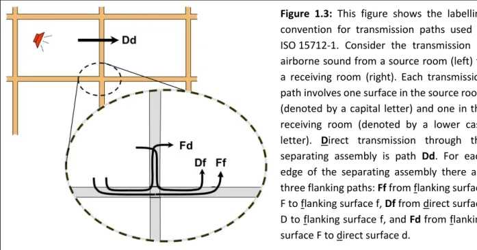
The calculations of ISO 15712-1 must combine the sound power transmitted via the direct path and via a set of flanking paths. To keep track of the sound transmission paths, it is useful to introduce the labeling convention for the paths that is used in ISO 15712-1 and is shown in Figure 1.3.
Figure 1.3: This figure shows the labelling
convention for transmission paths used in ISO 15712-1. Consider the transmission of airborne sound from a source room (left) to a receiving room (right). Each transmission path involves one surface in the source room (denoted by a capital letter) and one in the receiving room (denoted by a lower case letter). Direct transmission through the separating assembly is path Dd. For each edge of the separating assembly there are three flanking paths: Ff from flanking surface F to flanking surface f, Df from direct surface D to flanking surface f, and Fd from flanking surface F to direct surface d.
Note that the lette F o f de otes fla ki g su fa e, a d D o d de otes the su fa e fo direct transmission, i.e. the surface of the separating assembly. These surfaces may be either wall or floor/ceiling assemblies.
1.3.1. Calculation of the ASTC Rating
In Canada, building elements are normally tested according to the ASTM E90 standard, and building code requirements are given in terms of apparent sound transmission class (ASTC) determined from the apparent sound transmission loss (ATL) for the set of frequency bands from 125 Hz to 4000 Hz, following the procedure described in ASTM E413. Merging this context with using the ISO 15712-1 procedures in
this Guide, the te s di e t sound t a s issio loss a d fla ki g sound t a s issio loss ha e ee
introduced to provide consistency with ASTM terminology while matching the function of the direct and flanking sound reduction indices defined in ISO 15712-1.
The apparent sound transmission loss is the logarithmic expression of the total transmission factor (’ :
� = − log �′ dB Eq. 1.1
The total transmission factor (’ is al ulated f o a su of t a s issio factors for individual paths:
�′ = � + ∑ (� + � + � )
4 =
Eq. 1.2
The transmission factors are defined as follows:
’ is the ratio of the total sound power radiated into the receiving room relative to the soundpower incident on the separating element;
Dd is the ratio of the sound power radiated by the separating element relative to the sound powerincident on the separating element;
Df is the ratio of the sound power radiated by a flanking element f in the receiving room due tostructure-borne transmission from element D in the source room, relative to the sound power incident on the separating element;
Ff is the ratio of the sound power radiated by a flanking element f in the receiving room due tostructure-borne transmission from element F in the source room, relative to the sound power incident on the separating element;
Fd is the ratio of the sound power radiated by element d in the receiving room due tostructure-borne transmission from flanking element F in the source room, relative to the sound power incident on the separating element.
Each of the transmission factors
ijcan be related to a corresponding path transmission loss associatedwith a specific pair of surfaces by the following expressions:
Direct transmission loss (for the separating assembly) = − log � dB
Flanking transmission loss (for flanking path ij) = − log � dB Eq. 1.3
or conversely,
ij = − � /To connect this more obviously to standard laboratory test results, the expressions of Equations 1.1 to 1.3 can readily be recast in terms of sound transmission loss values, as shown in Eq. 1.4.
The apparent sound transmission loss (ATL) between two rooms (assuming the room geometry of Section
1.4.1 and neglecting the sound that by-passes the uildi g st u tu e, e.g. leaks, du ts,… is the esulta t
of the direct sound transmission loss (TL ) through the separating wall or floor element and the set of
flanking sound transmission loss contributions (TL , TL , and TL ) of the three flanking paths for
every junction at the edges of the separating element (as shown in Fig. 1.3) such that:
� = − ∙ log − . ∙ ���+ ∑ ( − . ∙ ���+ − . ∙ ��� + − . ∙ ���)
4 =
Eq. 1.4
Note that this equation differs slightly from the calculation of the apparent sound transmission defined in Equation 14 of ISO 15712-1. Eq. 1.4 of this Guide treats the set of paths at each edge of the separating assembly in turn to match the presentation for the examples in this Guide. Eq. 1.4 is universally valid for all building systems, and the remaining challenge is to find the right expressions to calculate the sound transmission for the different paths for the chosen building system and situation.
The standard ISO 15712-1 describes two methods of calculating the apparent sound insulation in a building: the Detailed Method and the Simplified Method. This Guide describes both methods to calculate the apparent sound insulation in a building.
The Simplified Method uses the single-number ratings (STC or Flanking STC for each transmission path, as appropriate) instead of the frequency-dependent sound transmission loss values, and yields the ASTC directly:
� � = − ∙ log [ − . ⋅ ��+ ∑4 ( − . ⋅ ��+ − . ⋅ ��+ − . ⋅ ��)
= ] Eq. 1.5
The Simplified Method has been widely used by designers in Europe for many years for calculations based
on RW data. Its primary advantage is the simplicity of the procedure, which makes it usable by
non-specialists. Although it is less rigorous than the Detailed Method, the differences between the results using the two methods are small, and the calculations for the Simplified Method use approximations that should ensure the results are slightly conservative.
The calculation process for each type of construction is presented in a separate chapter of this Guide: Concrete and masonry structures in Chapter 2
Cross-laminated timber (CLT) structures in Chapter 3
Lightweight wood-framed and steel-framed structures in Chapter 4 Hybrid structures integrating different types of construction in Chapter 5
The set of transmission factors used in this Guide is less general than the corresponding list of transmission factors in ISO 15712-1 to reflect the simplifications due to the Standard Scenario (see Section 1.4) and some further simplifications noted in the following cautions.
Cautions and limitations to examples presented in this Guide:
This Guide was developed to support the transition to ASTC ratings for sound control objectives in the National Building Code of Canada. Simplifications were made to meet the specific needs of that application, where sound insulation is addressed only in the context of multi-unit residential buildings. The simplifications include that:
Transmission around or through the separating assembly due to leaks at its perimeter or
penetrations such as ventilation systems are assumed negligible
.
Indirect airborne sound transmission (for example airborne flanking via an unblocked attic or crawl space) is assumed to be suppressed by normal fire blocking requirements.
For adjacent units in a multi-family residential building, these two issues should be dealt with by using normal good practice for fire and sound control between adjoining dwellings.
If this Guide is applied to situations other than separation between adjacent units in multi-family residential buildings, some of these issues may have to be explicitly addressed in the calculation process. For example, for adjoining rooms within a single office or home, flanking paths such as ventilation ducts or open shared plenum spaces may be an issue. The flanking sound transmission associated with these additional paths should be determined and included in the calculated ASTC. ISO 15712-1 includes specific guidance for such issues, and the examples in this Guide allow for such a correction. A worked example of a scenario with two side-by-side rooms and a door is presented in Appendix A2.
1.4. Worked Examples in this Guide
This Guide contains more than 50 worked examples that demonstrate the calculation of the ASTC rating for various construction types. Each worked example presents the pertinent physical characteristics of the wall and floor assemblies and their junctions, together with a summary of key steps in the calculation process for these constructions.
1.4.1. Standard Scenario for the Worked Examples in this Guide
The prediction of the sound transmitted in buildings depends not only on the construction details of the transmission paths, but also on the size and shape of each of the room surfaces and on the sound absorption in the receiving room. The ability to adjust the calculation to fit the dimensions in a specific building or to normalize to different receiving room conditions enables a skilled designer to obtain more accurate predictions.
For purposes of this Guide, where results are presented for a variety of constructions, easy and meaningful comparison of results is facilitated by calculating all the examples for a common set of room geometry and dimensions. This is particularly useful where only small changes are made between the construction details in the examples, since any change in the ASTC rating can then be attributed to the changes that were made in the construction details.
Therefore, a Standard Scenario has been adopted for all the examples, with the following constraints: Sound is transmitted between adjacent rooms, either side-by-side or one-above-the-other. The adjacent rooms are mirror images of each other, (with one side of the separating assembly
facing each room, and constituting one complete face of each rectangular room).
The Standard Scenario is illustrated in Figures 1.4 and 1.5, for the cases where one room is beside the other, or one is above the other, respectively.
Figure 1.4:
Standard Scenario for ho izo tal oo pai ase he e the pair of rooms are side-by side with a separating wall assembly between the two rooms.
Figure 1.5:
Standard Scenario for the e ti al oo pai case where one of the pair of rooms is above the other,
with the floor/ceiling assembly between the two rooms.
The pertinent dimensions and junction details are shown in Figures 1.4 and 1.5.
Note the labelling of junctions at the four edges of the separating assembly (J1 to J4) in Figures 1.4 and 1.5. These junction designations are used in the design examples throughout this Guide. For horizontal room pairs (i.e. rooms are side-by-side) the separating wall is 2.5 m high by 5 m wide,
flanking floor/ceilings are 4 m by 5 m and flanking walls are 2.5 m high by 4 m wide.
For vertical room pairs (i.e. one room is above the other) the separating floor/ceiling is 4 m by 5 m wide and flanking walls in both rooms are 2.5 m high.
In general, it is assumed that junctions at one side of the room (at the separating wall if rooms are side-by-side) are cross-junctions, while one or both of the other two junctions are T-junctions. This enables the examples to illustrate typical differences between the two common junction cases. For a horizontal room pair, the separating wall has T-junctions with the flanking walls at both the
façade and corridor sides, and cross-junctions at floor and ceiling.
For a vertical room pair, the façade wall has a T-junction with the separating floor, but the opposing corridor wall has a cross-junction, as do the other two walls.
Deviations from the Standard Scenario, such as for rooms with different dimensions or for room pairs where one room is an end unit with T-junctions instead of cross-junctions, can be calculated by substituting the appropriate room dimensions and junction details in the calculation procedures and in the worked examples in this Guide.
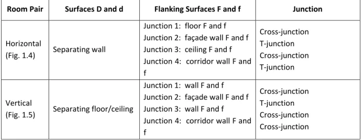
Following the labeling convention described in Figure 1.3, the labels for the flanking surfaces of the Standard Scenarios are detailed in the following Table 1.3.
Room Pair Surfaces D and d Flanking Surfaces F and f Junction
Horizontal
(Fig. 1.4) Separating wall
Junction 1: floor F and f Junction 2: façade wall F and f Junction 3: ceiling F and f Junction 4: corridor wall F and f Cross-junction T-junction Cross-junction T-junction Vertical
(Fig. 1.5) Separating floor/ceiling
Junction 1: wall F and f
Junction 2: façade wall F and f Junction 3: wall F and f Junction 4: corridor wall F and f
Cross-junction T-junction Cross-junction Cross-junction
1.4.2. Calculation Spreadsheets for the Worked Examples
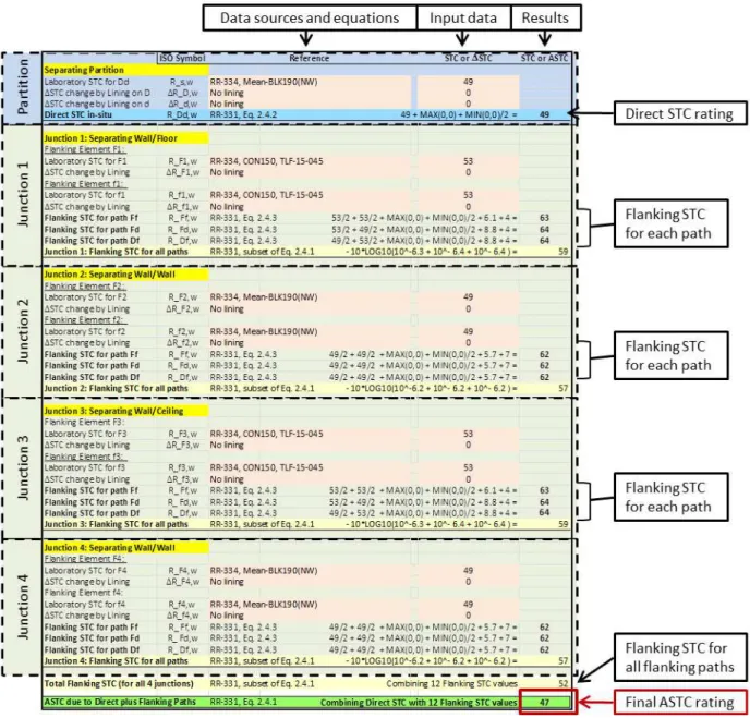
The calculation of the ASTC rating for each worked example is illustrated step by step in a calculation
spreadsheet. Figure 1.6 shows two examples of calculation spreadsheets – one for a calculation using the
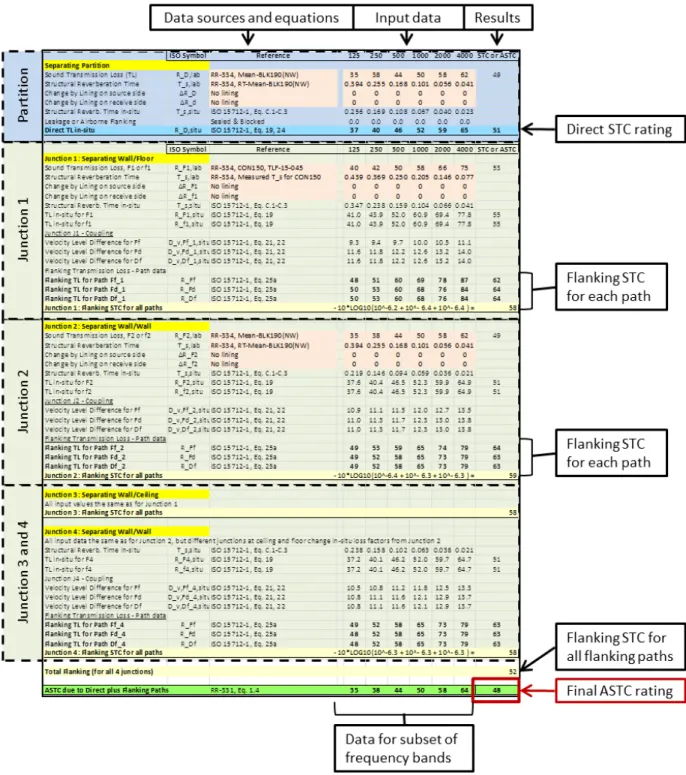
Detailed Method of ISO 15712-1, and one for a calculation using the Simplified Method. Colour is used to highlight input and output values in the worked examples:
Bright yellow is used to indicate section headings, i.e. blocks of data for the separating assembly and the four junctions
Light red is used to indicate input values
Blue is used to indicate the direct sound transmission loss, including the effect of in-situ loss corrections and any added lining(s) on the separating assembly
Pale yellow is used to indicate calculated values of the combined flanking sound transmission due to a set of flanking paths
Green is used to indicate the final result for the ASTC rating
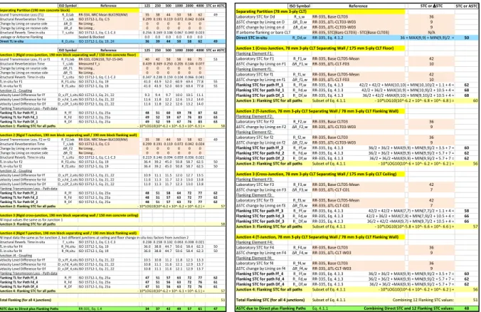
Figure 1.6: Examples of calculation spreadsheets for the determination of the ASTC rating: The layouts
for the Detailed Method (on the left) and the Simplified Method (on the right) are similar, but the former presents more detailed information. Larger versions of these images are given in the following discussion of each method.
ISO Symbol Reference 125 250 500 1000 2000 4000 STC or ASTC Separating Partition (190 mm concrete block)
Sound Transmission Loss (TL) R_D,lab RR-334, NRC Mean BLK190(NW) 35 38 44 50 58 62 49 Structural Reverberation Time T_s,lab ISO 15712-1, Eq. C.5 0.299 0.191 0.119 0.072 0.042 0.024 Change by Lining on source side ΔR_D No Lining , 0 0 0 0 0 0 Change by Lining on receive side ΔR_d No Lining , 0 0 0 0 0 0 Structural Reverb. Time in-situ T_s,situ ISO 15712-1, Eq. C.1-C.3 0.256 0.169 0.108 0.067 0.040 0.023 Leakage or Airborne Flanking Sealed & Blocked 0.0 0.0 0.0 0.0 0.0 0.0 Direct TL in-situ R_D,situ ISO 15712-1, Eq. 19, 24 36 39 44 50 58 62 49
ISO Symbol Reference 125 250 500 1000 2000 4000 STC or ASTC Junction 1 (Rigid cross-junction, 190 mm block separating wall / 150 mm concrete floor)
Sound Transmission Loss, F1 or f1 R_F1,lab RR-333, CON150, TLF-15-045 40 42 50 58 66 75 53 Structural Reverberation Time T_s,lab Measured T_s 0.439 0.369 0.250 0.205 0.146 0.077 Change by Lining on source side ΔR_F1 No Lining , 0 0 0 0 0 0 Change by Lining on receive side ΔR_f1 No Lining , 0 0 0 0 0 0 Structural Reverb. Time in-situ T_s,situ ISO 15712-1, Eq. C.1-C.3 0.347 0.238 0.159 0.104 0.066 0.041 TL in-situ for F1 R_F1,situ ISO 15712-1, Eq. 19 41.043.952.060.969.477.8 55 TL in-situ for f1 R_f1,situISO 15712-1, Eq. 19 41.043.952.060.969.477.8 55 Junction J1 - Coupling
Velocity Level Difference for Ff D_v,Ff_1,situISO 15712-1, Eq. 21, 22 9.3 9.4 9.7 10.010.511.1 Velocity Level Difference for Fd D_v,Fd_1,situISO 15712-1, Eq. 21, 22 11.611.812.212.613.214.0 Velocity Level Difference for Df D_v,Df_1,situISO 15712-1, Eq. 21, 22 11.611.812.212.613.214.0 Flanking Transmission Loss - Path data
Flanking TL for Path Ff_1 R_Ff ISO 15712-1, Eq. 25a 48 51 60 69 78 87 62 Flanking TL for Path Fd_1 R_Fd ISO 15712-1, Eq. 25a 49 52 59 67 76 83 63 Flanking TL for Path Df_1 R_Df ISO 15712-1, Eq. 25a 49 52 59 67 76 83 63 Junction 1: Flanking STC for all paths - 10*LOG10(10^-6.2 + 10^- 6.3 + 10^- 6.3 ) = 58 Junction 2 (Rigid T-Junction, 190 mm block separating wall / 190 mm block flanking wall)
Sound Transmission Loss, F2 or f2 R_F2,lab RR-334, NRC Mean BLK190(NW) 35 38 44 50 58 62 49 Structural Reverberation Time T_s,lab ISO 15712-1, Eq. C.5 0.299 0.191 0.119 0.072 0.042 0.024 Change by Lining on source side ΔR_F2 No Lining , 0 0 0 0 0 0 Change by Lining on receive side ΔR_f2 No Lining , 0 0 0 0 0 0 Structural Reverb. Time in-situ T_s,situ ISO 15712-1, Eq. C.1-C.3 0.219 0.146 0.094 0.059 0.036 0.021 TL in-situ for F2 R_F2,situ ISO 15712-1, Eq. 19 36.439.245.050.858.762.5 50 TL in-situ for f2 R_f2,situISO 15712-1, Eq. 19 36.439.245.050.858.762.5 50 Junction J2 - Coupling
Velocity Level Difference for Ff D_v,Ff_2,situISO 15712-1, Eq. 21, 22 10.911.111.512.012.713.5 Velocity Level Difference for Fd D_v,Fd_2,situISO 15712-1, Eq. 21, 22 11.011.311.712.313.013.8 Velocity Level Difference for Df D_v,Df_2,situISO 15712-1, Eq. 21, 22 11.011.311.712.313.013.8 Flanking Transmission Loss - Path data
Flanking TL for Path Ff_2 R_Ff ISO 15712-1, Eq. 25a 48 51 58 64 72 77 62 Flanking TL for Path Fd_2 R_Fd ISO 15712-1, Eq. 25a 48 51 57 63 72 77 62 Flanking TL for Path Df_2 R_Df ISO 15712-1, Eq. 25a 48 51 57 63 72 77 62 Junction 2: Flanking STC for all paths - 10*LOG10(10^-6.2 + 10^- 6.2 + 10^- 6.2 ) = 57 Junction 3 (Rigid cross-junction, 190 mm block separating wall / 150 mm concrete ceiling)
All input values the same as for Junction 1
Junction 3: Flanking STC for all paths 58 Junction 4 (Rigid T-junction, 190 mm block separating wall / 190 mm block flanking wall)
All input data the same as for Junction 2, but different junctions at ceiling and floor change in-situ loss factors from Junction 2 Structural Reverb. Time in-situ T_s,situ ISO 15712-1, Eq. C.1-C.3 0.238 0.158 0.102 0.063 0.038 0.021 TL in-situ for F4 R_F4,situ ISO 15712-1, Eq. 19 36.038.844.750.658.462.3 50 TL in-situ for f4 R_f4,situISO 15712-1, Eq. 19 36.038.844.750.658.462.3 50 Junction J4 - Coupling
Velocity Level Difference for Ff D_v,Ff_4,situISO 15712-1, Eq. 21, 22 10.510.811.211.812.513.3 Velocity Level Difference for Fd D_v,Fd_4,situISO 15712-1, Eq. 21, 22 10.811.111.612.112.913.7 Velocity Level Difference for Df D_v,Df_4,situISO 15712-1, Eq. 21, 22 10.811.111.612.112.913.7 Flanking Transmission Loss - Path data
Flanking TL for Path Ff_4 R_Ff ISO 15712-1, Eq. 25a 47 51 57 63 72 77 62 Flanking TL for Path Fd_4 R_Fd ISO 15712-1, Eq. 25a 47 51 56 63 72 76 61 Flanking TL for Path Df_4 R_Df ISO 15712-1, Eq. 25a 47 51 56 63 72 76 61 Junction 4: Flanking STC for all paths - 10*LOG10(10^-6.2 + 10^- 6.1 + 10^- 6.1 ) = 57 Total Flanking (for all 4 junctions) 51 ASTC due to Direct plus Flanking Paths RR-331, Eq. 1.4 34 37 42 49 57 61 47
ISO Symbol STC or DSTC STC or ASTC Separating Partition (78 mm 3-ply CLT)
Laboratory STC for Dd R_s,w RR-335, Base CLT03 36 Δ“TC change by Lining on D ΔR_D,w RR- , ΔTL-CLT -W 9 Δ“TC change by Lining on d ΔR_d,w RR- , ΔTL-CLT -W 9 If airborne flanking or bare CLT RR-335, STC(Bare CLT03) - STC(Base CLT03) N/A
Direct STC in-situ R_Dd,w RR-335, Eq. 4.1.2 36 + MAX(9,9) + MIN(9,9)/2 = 50 Junction 1 (Cross-Junction, 78 mm 3-ply CLT Separating Wall / 175 mm 5-ply CLT Floor)
Flanking Element F1:
Laboratory STC for F1 R_F1,w RR-335, Base CLT05-Mean 42 Δ“TC ha ge Li i g o F ΔR_F , RR- , ΔTL-CLT-F 10 Flanking Element f1:
Laboratory STC for f1 R_f1,w RR-335, Base CLT05-Mean 42 Δ“TC ha ge Li i g o f ΔR_f , RR- , ΔTL-CLT-F 10
Flanking STC for path Ff_1 R_ Ff,w RR-335, Eq. 4.1.3 42/2 + 42/2 + MAX(10,10) + MIN(10,10)/2 + 1.1 + 4 = 62 Flanking STC for path Fd_1 R_ Fd,w RR-335, Eq. 4.1.3 42/2 + 36/2 + MAX(10,9) + MIN(10,9)/2 + 10.5 + 4 = 68 Flanking STC for path Df_1 R_ Df,w RR-335, Eq. 4.1.3 36/2 + 42/2 +MAX(9,10) + MIN(9,10)/2 + 10.5 + 4 = 68 Junction 1: Flanking STC for all paths Subset of Eq. 4.1.1 - 10*LOG10(10^-6.2 + 10^- 6.8 + 10^- 6.8 ) = 60
Junction 2 (T-Junction, 78 mm 3-ply CLT Separating Wall / 78 mm 3-ply CLT Flanking Wall)
Flanking Element F2:
Laboratory STC for F2 R_F2,w RR-335, Base CLT03 36 Δ“TC ha ge Li i g o F ΔR_F , RR- , ΔTL-CLT -W 9 Flanking Element f2:
Laboratory STC for f2 R_f2,w RR-335, Base CLT03 36 Δ“TC ha ge Li i g o f ΔR_f , RR- , ΔTL-CLT -W 9
Flanking STC for path Ff_2 R_ Ff,w RR-335, Eq. 4.1.3 36/2 + 36/2 + MAX(9,9) + MIN(9,9)/2 + 3.5 + 7 = 60 Flanking STC for path Fd_2 R_ Fd,w RR-335, Eq. 4.1.3 36/2 + 36/2 + MAX(9,9) + MIN(9,9)/2 + 5.7 + 7 = 62 Flanking STC for path Df_2 R_ Df,w RR-335, Eq. 4.1.3 36/2 + 36/2 +MAX(9,9) + MIN(9,9)/2 + 5.7 + 7 = 62 Junction 2: Flanking STC for all paths Subset of Eq. 4.1.1 - 10*LOG10(10^-6 + 10^- 6.2 + 10^- 6.2 ) = 56
Junction 3 (Cross-Junction, 78 mm 3-ply CLT Separating Wall / 175 mm 5-ply CLT Ceiling)
Flanking Element F3:
Laboratory STC for F3 R_F3,w RR-335, Base CLT05-Mean 42 Δ“TC ha ge Li i g o F ΔR_F , RR- , ΔTL-CLT-C 7 Flanking Element f3:
Laboratory STC for f3 R_f3,w RR-335, Base CLT05-Mean 42 Δ“TC ha ge Li i g o f ΔR_f , RR- , ΔTL-CLT-C 7
Flanking STC for path Ff_3 R_ Ff,w RR-335, Eq. 4.1.3 42/2 + 42/2 + MAX(7,7) + MIN(7,7)/2 + 1.1 + 4 = 58 Flanking STC for path Fd_3 R_ Fd,w RR-335, Eq. 4.1.3 42/2 + 36/2 + MAX(7,9) + MIN(7,9)/2 + 10.5 + 4 = 66 Flanking STC for path Df_3 R_ Df,w RR-335, Eq. 4.1.3 36/2 + 42/2 +MAX(9,7) + MIN(9,7)/2 + 10.5 + 4 = 66 Junction 3: Flanking STC for all paths Subset of Eq. 4.1.1 - 10*LOG10(10^-5.8 + 10^- 6.6 + 10^- 6.6 ) = 57
Junction 4 (T-Junction, 78 mm 3-ply CLT Separating Wall / 78 mm 3-ply CLT Flanking Wall)
Flanking Element F4:
Laboratory STC for F4 R_F4,w RR-335, Base CLT03 36 Δ“TC ha ge Li i g o F ΔR_F , RR- , ΔTL-CLT-W 9 Flanking Element f4:
Laboratory STC for f4 R_f4,w RR-335, Base CLT03 36 Δ“TC ha ge Li i g o f ΔR_f , RR- , ΔTL-CLT-W 9
Flanking STC for path Ff_4 R_ Ff,w RR-335, Eq. 4.1.3 36/2 + 36/2 + MAX(9,9) + MIN(9,9)/2 + 3.5 + 7 = 60 Flanking STC for path Fd_4 R_ Fd,w RR-335, Eq. 4.1.3 36/2 + 36/2 + MAX(9,9) + MIN(9,9)/2 + 5.7 + 7 = 62 Flanking STC for path Df_4 R_ Df,w RR-335, Eq. 4.1.3 36/2 + 36/2 +MAX(9,9) + MIN(9,9)/2 + 5.7 + 7 = 62 Junction 4: Flanking STC for all paths Subset of Eq. 4.1.1 - 10*LOG10(10^-6 + 10^- 6.2 + 10^- 6.2 ) = 56
Total Flanking STC (for all 4 junctions) Subset of Eq. 4.1.1 Combining 12 Flanking STC values: 51
ASTC due to Direct plus Flanking Paths Eq. 4.1.1 Combining Direct STC and 12 Flanking STC values: 48 Reference
Calculation Spreadsheets for Worked Examples using the Detailed Method
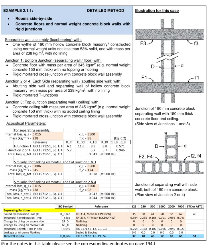
Worked examples demonstrating the calculation of the ASTC rating using the Detailed Method are presented in Sections 2.1, 2.2, 2.3, 3.2, 5.1, and 5.2.
The calculations using the Detailed Method are performed in the 16 one-third octave frequency bands between 125 Hz and 4000 Hz, but to save space data is only presented in six of these one-third octave bands (125 Hz, 250 Hz, 500 Hz, 1000 Hz, 2000 Hz, and 4000 Hz). It should be kept in mind that the data shown in the worked examples is only a subset of the actual data used for the calculations.
Within each spreadsheet, the Refe e e olu p ese ts the sou e of i put data. The source may be
indicated by an NRC report number and identifier for a laboratory test result, or by applicable equations and sections of ISO 15712-1 or their counterparts using ASTM ratings. Symbols and subscripts identifying the corresponding variable in ISO 15712-1 are given in the adjacent column.
To permit readers to better assess the worked examples using the Detailed Method, the spreadsheets show the single-number ratings (such as STC for each assembly and Flanking STC for specific paths) at intermediate steps during the calculation. Note that these single-number ratings shown at each stage of the calculation are presented only to provide readers with a convenient indication of the relative strength of the 13 sound transmission paths. The actual calculation at each step is performed in the individual one-third octave bands. The sound transmission loss values for the 13 paths are combined to arrive at the overall apparent sound transmission loss (ATL) for each frequency band. The ASTC rating is then calculated from the values for apparent sound transmission loss in the 16 one-third octave frequency bands between 125 Hz and 4000 Hz.
Under the headi g “TC o A“TC the examples using the Detailed Method present single-number ratings,
each calculated from a set of one-third octave band data according to ASTM E413, to provide a consistent set of summary single-number measures at each stage of the calculation:
STC values for the laboratory sound transmission loss of wall or floor assemblies
In-situ STC values for the calculated in-situ sound transmission loss of wall and floor assemblies Direct STC values for the in-situ sound transmission loss through the separating assembly
including the effect of linings
Flanking STC values calculated for each flanking sound transmission path at each junction including the effect of linings
Apparent STC (ASTC) values for the combination of direct and flanking transmission via all paths The Detailed Method worksheet for an example with side-by-side rooms is shown in Figure 1.7.
Calculation Spreadsheets for Worked Examples using the Simplified Method
Worked examples that demonstrate the calculation of the ASTC rating using the Simplified Method are presented in Sections 2.4, 3.1, 4.2, 4.3, and 5.3.
U de the headi g “TC or Δ“TC , the e a ples p ese t i put data dete ined from laboratory tests: STC values for the laboratory sound transmission loss of wall or floor assemblies
Δ“TC alues easu ed i the la o ato fo the ha ge i “TC due to addi g that li i g to the specified wall or floor assembly, as explained in Appendix A1 of this Guide
Flanking STC values for each flanking sound transmission path at each junction measured following ISO 10848 and re-normalized using Eq. 4.1.3 (for lightweight framed constructions) U de the headi g “TC o A“TC , the e a ples p esent the calculated values for sound transmission via specific paths:
Direct STC ratings for the in-situ sound transmission loss through the separating assembly including the effect of linings
Flanking STC ratings for each flanking sound transmission path including the effect of linings Apparent STC (ASTC) ratings for the combination of direct and flanking sound transmission paths The numeric calculations are presented step-by-step in each worked example, using compact notation consistent with the spreadsheet expressions:
For the calculation of the Direct STC and the Flanking STC, the expressions show the required calculation to account for linings on one or both sides of the bare assembly. These values are rounded to the nearest integer, for consistency with the corresponding measured values. For combining the sound power transmitted via specific paths, the calculation of Eq. 1.5 is
presented in several stages. Note that in the compact notation, a term for transmitted sound
power fraction such as − . ∙ becomes 10-7.4, if STC
ij = 74.
At each stage (such as the Flanking STC for the 3 paths at a given junction) the result is converted
into decibel form by calculating -10*log10 (transmitted sound power fraction) to facilitate
comparison of each path or junction with the Direct STC and the final ASTC result.
Within the spreadsheet for each worked example, the Refe e e olu p ese ts the sou e of the
input data. The source may be identified by an NRC report number and identifier for each laboratory test result, or by applicable equations and sections of ISO 15712-1 or their counterparts using ASTM ratings. Symbols and subscripts identifying the corresponding variable in ISO 15712-1 are given in the adjacent
1.4.3. Rounding and Precision in the Worked Examples
The value of the final ASTC rating obtained in each worked example depends slightly on the precision of the input data and on rounding of results at each stage of the calculation. There is no rounding approach explicitly specified in ISO 15712-1, but the worked examples in the ISO standard show input and calculated sound reduction index values rounded to 0.1 dB which is consistent with the requirements for presentation of results in the ISO standards for measuring laboratory sound transmission. The ASTM standards for the measurement of sound transmission in the laboratory and in the field (ASTM E90 and ASTM E336, respectively) specify that sound transmission loss values should be rounded to the nearest integer, which is arguably more representative of meaningful precision of the result.
The examples in this document follow the ASTM convention of rounding to the nearest integer for input sound transmission loss data from laboratory tests of wall or floor assemblies, for measured or calculated values of flanking sound transmission loss for individual paths, and for the apparent sound transmission loss calculated from the combination of direct and flanking paths. For input values measured according to ISO standards for which there is no ASTM counterpart, specific rounding rules were used as noted below: Sound transmission loss values from measurements according to ASTM E90, and values of DTL
calculated from such measurements were rounded to the nearest integer.
Structural reverberation times measured for laboratory wall or floor specimens or calculated for laboratory results according to Annex C of ISO 15712-1 were rounded to 3 decimal places.
Values of the vibration reduction index (Kij) at junctions between a separating assembly and an
assembly were rounded to the nearest 0.1 dB, both for results measured according to ISO 10848 and for those calculated using the equations from Annex E of ISO 15712-1.
Between the input values and the flanking transmission loss results for each path (which were rounded to the nearest integer), the worked examples are calculated to the full precision of the spreadsheet and interim values are presented to slightly higher precision to permit detailed comparisons for users treating these examples as benchmarks for their own worksheets.
When the calculated Flanking TL or Flanking STC value for a given path exceeds 90, the value is limited to 90, to allow for the inevitable effect of higher order flanking paths which make the higher calculated value not representative of the true situation. Further enhancements to elements in these paths will give negligible benefit. The consequence of this limit is that the Junction STC value for the set of 3 paths at each edge of the separating assembly cannot exceed 85, and the Total Flanking STC value for all 4 edges cannot exceed 79.
2. Buildings with Concrete or Concrete Masonry Walls and Concrete
Floors
This chapter begins with an introduction outlining the concepts of the detailed calculation method of ISO 15712-1. The following sections provide more focussed procedural guidance and worked examples for specific sets of wall, floor, and junction details for concrete and masonry buildings.
Airborne sound in a source room excites vibration of the wall and floor assemblies that form the bounding surfaces of the room. As discussed in Chapter 1, the apparent transmission between adjacent rooms includes the combination of direct airborne sound transmission through the separating assembly and structure-borne flanking sound transmission via the three pairs of wall and floor surfaces (one in the source room and the other in the receiving room) that are connected at each of the four edges of the separating assembly. The Detailed Method of ISO 15712-1 is focused on the balance between the input sound power and power losses (due to internal losses, sound radiation, and power flow into adjoining assemblies). This balance alters the direct transmission through each floor or wall assembly, and also the structure-borne transmission via the flanking surfaces.
More information on the direct and flanking sound insulation of hollow concrete block masonry wall assemblies connected to concrete floor assemblies can be found in NRC Research Report RR-334,
Appa e t “ou d I sulatio i Co ete Blo k Buildi gs. The epo t p o ides the data fo di e t a d
flanking sound insulation for a variety of concrete block building configurations.
Direct Transmission through the Separating Assembly
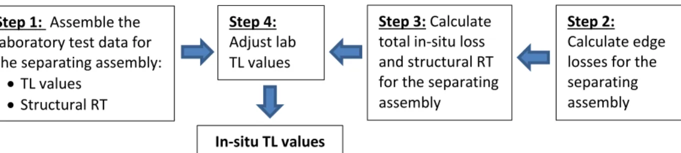
Figure 2.1 shows the steps required to transform the laboratory sound transmission data through a bare separating assembly into the direct in-situ transmission loss. The steps are described in more detail below the figure. The transformation requires a correction to adjust for the differences between losses in a laboratory test specimen and the losses when the assembly is connected to adjoining structures in-situ in the building. Note that all of the calculations are performed in one-third octave bands.
Figure 2.1: Steps to calculate the in-situ transmission loss for the separating assembly.
Step 1: Assemble the required laboratory test data:
o Laboratory sound transmission loss (TL) values measured according to ASTM E90 for the floor
or wall assembly of bare concrete or masonry without added linings. For the treatment of linings in the calculation, please see Section 2.3.
o Structural reverberation time (TS) measured according to ISO 10848-1 in the laboratory, if
available. If measured data is not available, a conservative estimate of the total loss factor for a laboratory specimen can be calculated from Eq. C.5 of Annex C of ISO 15712-1.
o Dimensions and mass per area for each of the wall and floor assemblies (without linings).
o The coincidence frequency for each of the wall and floor assemblies (without linings).
Step 2: Calculate the edge losses for the separating assembly in-situ:
o For each edge of the separating assembly, calculate the vibration reduction index (Kij) between
the separating assembly and each attached assembly using the appropriate case from Annex E of ISO 15712-1. These values depend on the junction geometry and on the ratio of the mass per area for the assemblies.
o For each edge, calculate the resulting absorption coefficient using the values of Kij and the
coincidence frequency (frequency at which the wavelength on the element and in surrounding air coincide) for the attached assemblies in Eq. C.2 of ISO 15712-1.
Step 3: Calculate total loss for the separating assembly and its in-situ structural reverberation time:
o Use the 2nd equation of Eq. C.1 of ISO 15712-1 to calculate the combination of internal losses,
radiation losses and edge losses. A comparison between the values calculated for a common surface for a vertical pair of rooms and a horizontal pair of rooms gives a check on the loss calculations. The total loss is frequency-dependent for most junction types. Note: the worked examples only give the value for the 500 Hz one-third octave band as a benchmark value.
o Use the 1st equation of Eq. C.1 of ISO 15712-1 to calculate the resulting structural reverberation
time of the assembly.
Step 4: Calculate the in-situ TL values for the separating assembly using the ratio of the structural reverberation times according to Eq. 19 in Section 4.2.2 of ISO 15712-1.
Step 4:
Adjust lab TL values
Step 1: Assemble the
laboratory test data for the separating assembly:
TL values Structural RT
Step 3: Calculate
total in-situ loss and structural RT for the separating assembly
Step 2:
Calculate edge losses for the separating assembly
Transmission via Flanking Elements
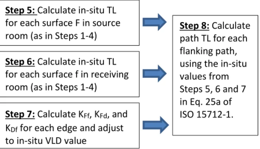
A similar procedure is required to adjust the flanking sound transmission loss of each flanking path for in-situ losses associated with the connecting junction and the two wall or floor surfaces that comprise the flanking path. The calculation process is presented in Figure 2.2, and each step is subsequently explained.
Figure 2.2: Steps to calculate the flanking transmission loss for each flanking path.
Step 5: Calculate the in-situ TL values for each flanking assembly F in the source room by repeating the
procedure of Steps 1 – 4 for these assemblies. Note that for an assembly of concrete
(cast-in-place concrete or precast concrete panels or hollow concrete block masonry) the coincidence frequency is below 125 Hz. Hence the radiation efficiency is equal to unity and the resonant sound transmission loss (required for these calculations) is equal to the sound transmission loss measured in the standard ASTM E90 laboratory test.
Step 6: Calculate the in-situ TL values for each flanking assembly f in the receiving room by repeating the
procedure of Steps 1 – 4 for these assemblies. Note that because of the symmetry in the Standard
Scenario used in this Guide and because the preceding calculation for direct sound transmission provides in-situ values for surfaces D and d, the examples in this Guide require Steps 5 and 6 for only 4 of the room surfaces: a floor/ceiling assembly, a separating wall, a corridor wall, and a façade wall. Applying the Detailed Method to rooms with other geometries than in the Standard Scenario may require further calculations.
Step 7: Calculate the in-situ velocity level difference (VLD) for the junction attenuation for each path:
o Calculate the vibration reduction index (Kij) between the pair of assemblies using the
appropriate case from Annex E of ISO 15712-1.
o Calculate the VLD for the junction of each flanking path using Eq. 21 and 22 of ISO 15712-1.
Step 5: Calculate in-situ TL
for each surface F in source room (as in Steps 1-4)
Step 6: Calculate in-situ TL
for each surface f in receiving room (as in Steps 1-4)
Step 7: Calculate KFf, KFd, and
KDf for each edge and adjust
to in-situ VLD value
Step 8: Calculate
path TL for each flanking path, using the in-situ values from Steps 5, 6 and 7 in Eq. 25a of ISO 15712-1.
Combining Direct and Flanking Sound Transmission
Step 9: Combine the sound power transmitted via the direct path through the separating assembly and the 12 flanking paths (3 at each edge of the separating assembly).
o Use Equations 1.4 in Section 1.4 of this Guide (equivalent to Section 4.1 of ISO 15712-1) to
calculate the apparent transmission loss (ATL).
o Use the resulting values of the apparent transmission loss in the procedure of ASTM E413 to
calculate the apparent sound transmission class (ASTC) rating.
From Step 4:
Take in-situ Direct TL values (including effect of linings)
From Step 8:
Take Flanking TL values (including effect of linings) for each flanking path
Step 9: Calculate
Apparent TL using the equations in Section 1.4, and calculate ASTC from these values
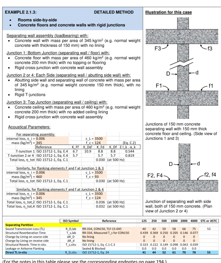
2.1. Rigid Junctions in Concrete and Concrete Masonry Buildings
This section presents worked examples for the most basic sort of concrete and masonry building which has structural floor slabs of bare concrete and walls of bare concrete or masonry connecting at rigid cross-junctions or T-cross-junctions.
Ba e indicates an assembly of concrete or masonry without a lining such as an added gypsum
board finish on the walls or ceiling, or flooring over the concrete slab. For an assembly of concrete or normal weight hollow concrete block masonry, the a e su fa e ould e pai ted o sealed, or have a thin coat of plaster without appreciably changing the sound transmission. However, these simple linings significantly improve the sound transmission properties of hollow concrete block masonry walls constructed of lightweight units. In practice, most buildings have wall finishes (and usually also ceiling finishes) of gypsum board mounted on some sort of lightweight framing, and some sort of flooring over the concrete. The calculations to deal with such linings are presented in Section 2.3. The examples in Section 2.1 and 2.2 have placeholders for including the effect of such linings, but those corrections have been set to zero.
Rigid i plies that the assemblies meeting at the junction are firmly bonded so that bending
vibration is effectively transmitted between the elements. Loadbearing junctions are always rigid, whereas non-loadbearing junctions may or may not be rigid.
The calculations in this section follow the steps of the Detailed Method of ISO 15712-1, as described at the beginning of Chapter 2. The approximations of the calculation make it most suitable for ho oge eous, lightl da ped st u tu al ele e ts whose coincidence frequency is below the frequency
range of interest (taken here as below about 125 Hz), and for which an average value of Kij suitable for a
rigid junction of homogeneous assemblies is appropriate. Homogeneous concrete walls and floors and hollow concrete block masonry walls of several types fall in this category.
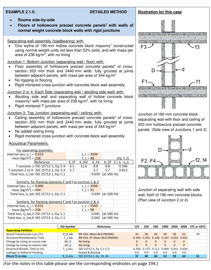
Hollowcore precast concrete floors are not homogeneous and isotropic. However, in laboratory testing of mock-up junctions of hollow concrete block masonry walls with hollowcore concrete floors it was shown that the methods of ISO 15712-1 and the vibration reduction index values of Annex E of ISO 15712-1 are still appropriate to use for these types of constructions. The measurements on the junction were conducted with the cores of the hollowcore panels oriented perpendicular to the junction. It is expected that hollowcore panels with the cores oriented parallel to the junction would yield similar or higher vibration reduction index values, and hence the vibration reduction index values from Annex E of ISO 15712-1 are appropriate to use independent of core orientation.
Based on the findings described above, homogeneous (cast-in-place and precast) concrete walls and floors, hollow concrete block masonry walls, and hollowcore precast concrete floors are all treated in the