HAL Id: in2p3-00374042
http://hal.in2p3.fr/in2p3-00374042
Submitted on 7 Apr 2009HAL is a multi-disciplinary open access archive for the deposit and dissemination of sci-entific research documents, whether they are pub-lished or not. The documents may come from teaching and research institutions in France or abroad, or from public or private research centers.
L’archive ouverte pluridisciplinaire HAL, est destinée au dépôt et à la diffusion de documents scientifiques de niveau recherche, publiés ou non, émanant des établissements d’enseignement et de recherche français ou étrangers, des laboratoires publics ou privés.
of EuroTeV results on the optical design of the Linear
Collider Beam Delivery System)
D. Angal-Kalinin, F. Jackson, J. Jones, R. Appleby, R. Barlow, A. Scarfe, A.
Toader, D. Toprek, O. Delferrière, M. Durante, et al.
To cite this version:
D. Angal-Kalinin, F. Jackson, J. Jones, R. Appleby, R. Barlow, et al.. The BDSLD task: Summary and deliverables (Overview of EuroTeV results on the optical design of the Linear Collider Beam Delivery System). 2009, pp.1-12. �in2p3-00374042�
The BDSLD task: Summary and deliverables
D. Angal-Kalinin, F. Jackson, J. Jones STFC, Daresbury Laboratory, UK
R. Appleby, R. Barlow, A. Scarfe, A. Toader, D. Toprek University of Manchester, UK
O. Delferrière, M. Durante, F. Kircher, O. Napoly, J. Payet, C. Rippon, D.Uriot, R. Versteegen
CEA/DSM/DAPNIA, Saclay, France
P. Bambade, J. Brossard, S. Cavalier, O. Dadoun, G. Le Meur, F. Touze LAL/IN2P3, France
D. Schulte, R. Tomas , J. Resta-Lopez, G. Rumolo, F. Zimmermann CERN, Geneva
January 22, 2009
Abstract
This report is the deliverable of the EUROTeV Beam Delivery System Lattice Design (BDSLD) and gives an overview of the published results.
1 Introduction
The lattice design of the beam delivery system of the linear collider has to satisfy several design constraints:
! demagnifications of the beams to achieve nanometer level beam sizes at the interaction point.
! collimation of the beam halo to ensure that the background in the detector is minimum (work done in close collaboration with COLSIM task from ILPS workpackage).
! provision of diagnostics sections for correcting the coupling and measuring the emittance as well as to measure the important physics parameters such as polarisation and energy.
! Safe extraction of the beam after the collision (work done in close collaboration with PCDL task in ILPS workpackage [1]).
The BDSLD design task aimed at designing the lattice designs for both the International Linear Collider (ILC) as well as for the Compact Linear Collider (CLIC). This report summarises the activities done under this task.
2 Lattice design
2.1 ILC
The lattice design of the ILC beam delivery system has been pursued within EUROTeV as a part of International global design effort. During the first ILC workshop at KEK in November 2004 after the technology decision for the linac technology, the beam delivery and machine detector interface groups decided to have a working hypothesis to have two interaction regions, one with a large crossing angle and one with a small crossing angle [2]. The collimation and final focus system lattice designs were adapted from the Next Linear Collider (NLC) design with modifications for survivability of the spoilers and to achieve the beam parameters at the interaction point. These designs were evolved over last four years and a reference design report was published [3]. The proposed configuration for the beam delivery system in this report is a single interaction region at 14 mrad crossing angle with two complementary detectors in a push pull configuration [4]. The small crossing angles configurations remain as alternative configurations.
The lattice repository for the ILC RDR lattices is available at: http://www-project.slac.stanford.edu/ilc/acceldev/beamdelivery/rdr/
2.1.1 Small crossing angle extraction schemes
The large crossing angle configuration allows more convenient spent beam extraction and the separate channel for the outgoing beam allows better control of highly disrupted beam. This makes it possible to provide beam optics for downstream polarisation and energy measurements. But, it adds complexity to the incoming beam due to crossing angle and depends on the crab crossing scheme. Small crossing angle schemes provide simpler pre-collision dynamics and have physics advantage but with increased difficulty to transport the
extracted beam. Since the large crossing angle design was matured (was developed earlier for the NLC design), the team concentrated on developing the small crossing solutions, viz; 2 mrad crossing angle and the modified head-on scheme proposed during Snowmass 2005. In the 2 mrad extraction scheme, the outgoing beam has an angle of 2 mrad angle at the interaction point and thus passes off-axis in the QD0 magnet of the incoming beam as shown in figure 1. The outgoing beam gets dipole kick and deflected outwards. To keep the separation from incoming beam, the outgoing beam passes through the reduced pocket field region of the next quadrupole magnet QF1. Initially, the 2 mrad crossing angle design attempted to include special optics for the downstream energy and polarisation measurements as in the large crossing angle configuration [5, 6]. But, it was proved to be inadequate and expensive due to its complexity. However, the comparison of backgrounds in the detector for the large and small crossing angle designs favoured lowering of the crossing angle till separate channels are possible with the compact superconducting magnets developed at Brookhaven National Laboratory. Due to the cost constraints, the final Reference Design configuration finally has only one interaction region with possibility of two complementary detectors in a push-pull operation.
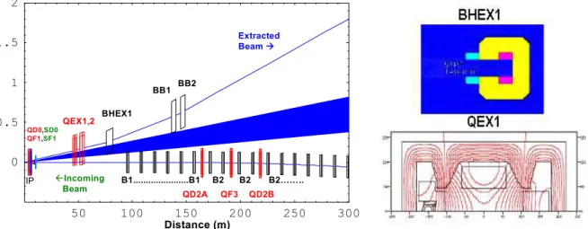
The efforts continued to optimise this design to make it economical with plausible magnet designs. Using tracking studies of beam losses with high statistics, the final doublet was optimised [7, 8] for beamstrahlung losses evaluated in realistic conditions [9]. The design has flexibility in the overall geometry in order to accommodate various dump locations [10, 11, 12]. The design does not include original post-collision polarisation and energy diagnostics, but there are different ideas to include these measurements in future upgrades. Figure 1 shows the layout of minimum extraction line for 2 mrad with designs for BHEX1 and QEX1 [13]. In the dipole magnet BHEX1, the incoming beam passes at 27cm to the left of the extracted beam and the quadrupole component of the leakage field can be absorbed in the re-fitted final focus optics. The QEX1 magnet uses iron and permanent magnets to shield the leakage field on the incoming beam. The field at the incoming beam location on the left side of the quadrupole is less than 10G.
50 100 150 200 250 300 0 0.5 1 1.5 2 BB1 BHEX1 !Incoming Beam Extracted Beam " QEX1,2 QD0, QF1, QD2A QF3 QD2B IP Distance (m) SD0 SF1 BB2 B1...B1 B2 B2 B2…….. 2 50 100 150 200 250 300 0 0.5 1 BB1 BHEX1 !Incoming Beam Extracted Beam " IP Distance (m) SD0 SF1 BB2 B1...B1 B2 B2 B2…….. 1.5 QEX1,2 QD0, QF1, QD2A QF3 QD2B
Fig. 1: Layout of 2mrad extraction line {Left}. Magnet designs for BHEX1 and QEX1 {right}
The modified head-on scheme shown in figure 2 is based on deflecting the outgoing beams horizontally with electrostatic separators located behind the final doublet and followed by a defocusing quadrupole centred on the incoming beam line ‘QD2A’ to produce a complementary deflection before extraction in a septum magnet [14]. The effect of parasitic
crossings coupled to the kink instability of the collision have been evaluated and found acceptable for most of the parameter space [15,16]. The final focus system has been modified to accommodate the electrostatic separators. The first extraction stage uses electrostatic separators based on LEP experience. The split type electrodes are placed inside a dipole which doubles the kick for the outgoing beam and cancels the kick for the incoming beam. Figure 2 shows the split type electrode and layout of the separators in the tunnel. The power loss in the electrostatic separators has been estimated [17]. The technical challenges of this scheme including magnets, collimators, and electrostatic separator failures have been studied [18]. A minimum extraction line has been studied without downstream polarimetry and spectrometry like in the 14 mrad design but alternative ideas exist to do such measurements near the interaction region.
Fig. 2: Layout of modified head-on extraction scheme {Left}. Layout of electrostatic separators with split electrodes in the enlarged tunnel {Right}.
2.1.2 Final focus optimisation procedure
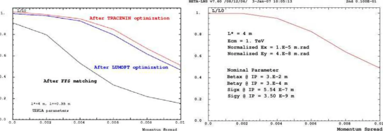
The design of the final focus system adopted for the ILC is based on local chromaticity correction and needs careful cancellations of geometric and chromatic aberrations due to the interleaved nature of the sextupoles in this scheme. An automatic procedure which realizes simultaneously the demagnification, the chromatic correction and the aberration minimization of the final focus beam line, has been completed [19]. It uses analytical computations of the IP beam sizes based on two external code results, TRANSPORT and MADX-PTC, and two minimization algorithms. In a second and much slower step, the code TRACEWIN is used to track a particle cloud and optimise the luminosity by minimizing the rms beam spot sizes at IP. This procedure is now used routinely to optimize the ILC beam delivery systems for 500 GeV and 1 TeV centre of mass energies. Figure 3 shows the results of the final focus optimisation process.
Fig. 3: Automated final focus tuning
2.1.3 Collimation depths and collimation performance
The collimation depths were estimated for the various evolving ILC BDS configurations with different crossing angles [20,21]. Figure 4 shows the collimation depths for 14 mrad and 2 mrad configurations. The collimation depths decide the openings of the spoilers in the BDS, which can offer strong wake field kicks due to their small opening gaps leading to deterioration of the beam sizes leading to loss of luminosity at the collision point. The optimised 14 mrad deck in the baseline did not demonstrate good collimation efficiency, compared to the NLC design. To improve the collimation performance, the energy spoiler was tightened with respect to its nominal design aperture, which leads to an increase in the jitter amplification factor. In order to improve the performance, the phase advances between the FD and the spoilers need to be matched correctly, whilst maintaining good bandwidth. The optimisation procedure has been developed to achieve this for the BDS decks. These optimizations lead to improvement in the collimation performance [22, 23]. The improvement in the collimation performance is shown in figure 5. The optimised lattice, in which it is assumed that the energy spoiler can be opened up vertically, shows much lower emittance dilution both in the PLACET simulations and the analytical prediction. The simulations of beam energy jitter suggest that chromatic effects will dominate over wakefield effects [24]. The collimation work is done in strong collaboration with the COLSIM task of Work Package 6 (ILPS).
Fig. 5: Collimation performance improvement after lattice optimisations. Original is the RDR lattice and opt1 and opt2 are the two different optimised solutions.
2.1.4 Study of the 14 mrad interaction region
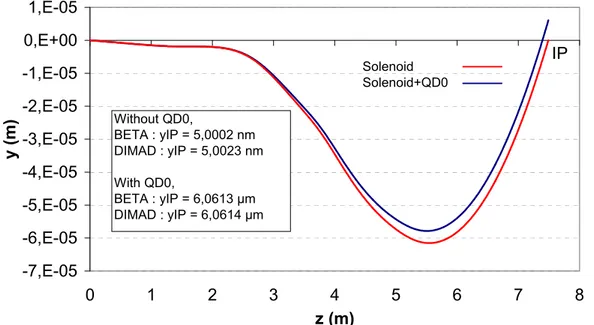
In view of understanding the tuning procedure of the 14 mrad final focus system, a program of calculating the beam properties (trajectory and beam matrix) through the complex set of final doublet, corrector, solenoid, anti-solenoid, and detector-integrated-dipole magnets has been launched[25]. It will use tracking through the superposition of the field maps of these various magnets (see Fig 6) and tracking through the matrices which describe the magnetic elements. Both methods are in agreement. The results show that the vertical deviation caused by the 4 T detector solenoid alone is about 5 nm at the IP whereas with the detector solenoid and the final quadrupole, located at 4.6 m from the IP, the vertical deviation at the IP is about 6 "m (see Fig.6). -7,E-05 -6,E-05 -5,E-05 -4,E-05 -3,E-05 -2,E-05 -1,E-05 0,E+00 1,E-05 0 1 2 3 4 5 6 7 8 z (m) y ( m ) Without QD0, BETA : yIP = 5,0002 nm DIMAD : yIP = 5,0023 nm With QD0, BETA : yIP = 6,0613 µm DIMAD : yIP = 6,0614 µm Solenoid Solenoid+QD0 IP
Figure 6: Vertical orbits in the solenoid, with and without QD0, !c = 7 mrad, l* = 4.6 m
The simultaneous correction of the coupling and the vertical displacement with a set of weak anti-solenoids is ongoing. An example of such a set is shown on Fig 7.
-2 -1 0 1 2 3 4 5 0 2 4 6 8 Solenoid axis, z (m) Bz ( T ) Detector field
Weak anti-solenoid field 1 Weak anti-solenoid field 2 Detector + Weak anti-solenoids
IP
Figure 7: Detector solenoid and weak anti-solenoid field
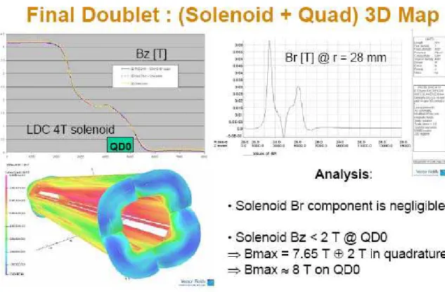
2.1.5 Magnetic field calculations of the solenoid-quadrupole configuration 2.1.5.1 Feasibility of the final superconducting quadrupole
Using “OPERA3D Modeller”,a complete magnetic 3D calculation of the insertion of a 250 T/m superconducting final focus quadrupole in the ILC-LDC (then ILD) detector 4 T solenoid magnet has been performed (see Fig.8). These studies showed that for l* > 3m the added longitudinal and radial components of the solenoid fringe field are small enough not to exceed the critical magnetic field on the quadrupole coils even for a NbTi conductor.
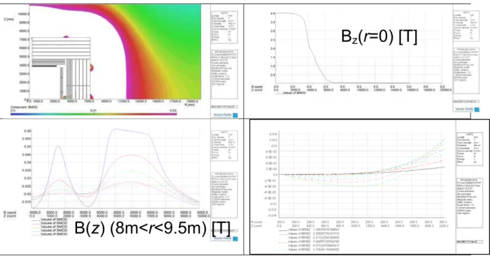
2.1.5.2 Optimisation of the ILD detector solenoid design
New magnetic calculations have been done with the ILD Collaboration LoI parameters:
Bo = 4 T nominal, 3.5 T operation Rint coil = 3 590 mm
Rext coil = 3 940 mm L coil = 3 672 x 2 mm
Stray field (@ 3.5 T):
.Bext " 200 G @ z=10 m from I.P.
.Bext " 200 G @ at (Rout + 1.5 - 2 m) in the radial direction
A solution, so called ILD-v2, which meets the specifications, has been found (see Fig.9). This work has been presented at the ILD workshop at Cambridge, UK in September 2008.
Figure 9: ILD-v2 detector solenoid design at 4 T
B
z(r=0) [T]
B(z) (8m<r<9.5m) [T]
These studies have established the feasibility of the insertion of a Nb3Sn final focus quadrupole in the ILC-LDC (then ILD) detector 4 T solenoid magnet for l* > 3m.
2.2 CLIC
Due to the pulse time structure and the tighter beam size requirements at the interaction point, the collimation, machine protection and the final focus systems need different design approach for CLIC. Several design iterations happened over the period of EUROTeV. In the following the modifications of the different sections of the CLIC Beam Delivery System are described following the natural beam line ordering: beam diagnostics, collimation, final focus and post-collision sections.
The CLIC beam diagnostics section was designed in 2007 and described in [26]. It fulfills the needs of coupling correction and emittance measurement. The design assumes a beam size measurement with 10% relative error at 1 micrometer vertical beam size. Conceptual energy and polarization measurements have also been devised during this period, see [27] and [28], respectively.
The collimation system has been thoroughly reviewed in [29]. This was required due to the change of beam parameters presented in [30]. One of the critical aspects of the CLIC collimation is the survivability of the spoilers. The review [29] positively verified this point, however the temperature of the collimators reaches the fracture level after the impact of a full CLIC beam. The consequences of the fracture should be minor but are presently under discussion. The energy and horizontal collimation efficiencies have been proved to be within the desired levels, however the vertical collimation efficiency seems to have deteriorated for the new parameters. This is also under investigation.
Another critical aspect of the collimation system is the wakefields experienced by the beam when traveling trough the tight apertures required for an efficient collimation. Many studies have addressed this issue [27,29,31] showing that this effect could limit the machine performance, therefore needs further studies.
An alternative collimation system for CLIC has been fully studied and characterized [32]. This new collimation system benefits from the non-linear fields of skew sextupoles to reduce the deposition energy density at the collimator, increasing its survival probability. The main disadvantage of the non-linear collimation is the luminosity loss, however the same optimization algorithm used for the FFS [33] could be applied to the non-linear collimation system to increase the baseline design luminosity by a factor of two.
The CLIC final focus system (FFS) has been designed based on the local chromaticity correction scheme. However, important chromatic aberrations deteriorate the performance of the system. Large efforts have been devoted to the development of algorithms for the optimization of the final focus system. These algorithms are based on the computation of the higher orders of the map using MAD-X and PTC followed by a post-processing using MAPCLASS [33, 34, 35]. The CLIC FFS was optimized in four main areas: non-linear aberrations, focusing, dispersion and length of the system. After cancelling the non-linear aberrations it is possible to apply stronger focusing until new aberrations arise. It was also found that reducing the FFS dispersion by about a 20% led to an optimum in IP beam size. After all these optimisations, the total luminosity was improved by 70%.
The length of the final focus was also reduced. This has the advantages of a shorter tunnel and a reduction of the chromatic aberrations. The length between the last quadrupole and the IP (the L*) is reduced from 4.3m to 3.5m. This should alleviate the chromatic aberrations. A lot of effort has been put in the optimization of the new and shorter FFS. Indeed a larger total luminosity has been achieved with the new FFS. However the peak luminosity is the same for both systems due to the fact that it is saturated by the beamstrahlung effect, i.e. the beam-beam interaction at the IP. In summary there are now two FFS systems with similar performance but different total lengths and different L*. A shorter beam delivery system at lower energy 500 GeV CM has been developed.
Final Focus tuning has become a critical issue. By tuning we understand the process of bringing a perturbed system to its ideal performance by varying the available parameters. A first look into tuning strategies was presented in [36] assuming the existence of some ideal knobs that would vary selected correlations of the IP particle distribution. The results were very promising, however some of the required knobs could not be designed for a large enough range. In particular, the knobs involving the vertical plane worked perfectly but the linear range of the horizontal knobs was not sufficient.
The use of knobs was abandoned and minimization algorithms like the Simplex are now used with all the variables of the FFS [37]. Assuming realistic errors and using the luminosity signal as the quantity to maximize a statistical study over more than 100 machines yielded 80% of the cases giving more than 80% of the luminosity after tuning. This result is not fully satisfactory; the goal is 90% of the seeds giving 90% of the luminosity. Therefore an improvement of the tuning algorithms should be pursued. This study is strongly related to the ATF2 future experience, where a similar final focus should be tuned to reach vertical beam sizes below 40nm.
A general lattice repository for CLIC can be found at [38].
2.3 BDS test facilities
The BDS lattice design team continued to support the optics designs for the End Station A facility at SLAC providing the different beam optics requirements for collimator wake field, energy spectrometer experiments [39].
The ATF2 proposal at the Accelerator Test Facility at KEK will experimentally verify the local chromaticity correction system to demonstrate the nominal vertical beam spot size of 37 nm. Various tuning procedures have been studied and proposed for ATF2, which will provide valuable feedback to the designs of future linear colliders [40, 41].
In order to directly extrapolate the future ATF2 experience to the CLIC project, it has been proposed in [42] to reduce the ATF2 IP vertical beta function by a factor of 4 compared to the design value. This will allow experimental verification of final focus chromaticity levels similar to the pushed-ILC and CLIC. Furthermore this could in principle reduce the IP beam size by a factor of two, what would yield the unique opportunity to study the tuning difficulty versus IP spot size.
The CLIC Test Facility (CTF3) has hosted a variety of tests of alignment algorithms and the challenge of fully automating these procedures to be ready for application in the future linear collider beam delivery system [43].
3 Conclusion
Different Beam delivery system lattice designs have been studied over the period of EUROTeV for both the ILC and CLIC. The simulations procedures have been developed to optimise the designs of collimation, final focus and extraction systems. The lattice repositories are available for both the ILC and CLIC.
Acknowledgement
This work is supported by the Commission of the European Communities under the 6th Framework Programme “Structuring the European Research Area”, contract number RIDS-011899.
References
1. P. Eliasson et al, “Results of the EUROTeV post collision Line Design (PCDL) Task”, EUROTeV-Report-2008-063.
2. D. Angal-Kalinin et al, “Optics and Layout Summary, Proceedings of Snowmass”, August 2005.
3. “International Linear Collider Reference Design Report”, Volume 3, ILC-Report-2007-001.
4. A. Seryi et al, “Design of the beam delivery system for the International Linear Collider”, Proceedings of PAC2007.
5. D.Angal-Kalinin et al, “Optics of the extraction line for 2 mrad crossing angle”, EUROTeV-Report-2006-001.
6. R. Appleby et al, “The 2 mrad crossing angle interaction region and extraction line”, EuroTeV-Report-2006-053.
7. R. Appleby and P. Bambade, “Improved final doublet designs for the ILC baseline small crossing angle scheme”, EUROTeV-Report-2006-022, also published in JINST 1, P10004 (2006).
8. R. Appleby et al, “Improved final doublet parameters for the ILC 2mrad interaction region”, EUROTeV-Memo-2007-001
9. R. Appleby and P. Bambade, “Photon production at the interaction point of the ILC”, EUROTeV report-2007-014, arXiv:0803.3519.
10. R. Appleby et al, “Extraction line optics for the improved 2mrad ILC crossing angle layout”, EuroTeV-Memo-2007-004.
11. R. Appleby et al, “Improved 2 mrad crossing angle layout for the International Linear Collider”, EUROTeV-Report-2007-022.
12. R. Appleby et al, “The 2 mrad crossing angle scheme for the International Linear Collider”, EUROTeV-Report-2008-034.
13. R. Appleby et al, “Panofsky quadrupole parameters for the ILC 2mrad Alternative crossing angle scheme”, EUROTeV-memo-2007-005.
14. J. Payet et al, “Design of an interaction region with head-on collisions for the ILC”, EUROTeV-Report-2006-083.
15. O. Napoly, J. Payet, C. Rippon, “Evaluation of the multi-bunch kink instability in ILC head-on collisions”, EUROTeV-Report-2006-018
16. J. Brossard et al, “Evaluation of luminosity reduction in the ILC head-on scheme from parasitic collisions”, EUROTeV-Report-2007-052.
17. J. Brossard, P. Bambade and O. Napoly, “Power loss estimation in the electrostatic separators of the ILC alternative head-on scheme at 500 GeV in the Centre-of-Mass”, EuroTeV-memo-2007-003.
18. O. Napoly et al, “Technical challenges for head-on collisions and extraction at the ILC”, EuroTeV-report-2007-043.
19. J. Payet et al, “Automatic Luminosity Optimizations of the ILC head-on beam delivery system”, Proceedings of PAC 2007.
20. F. Jackson, “Estimation pf collimation depths for 20 and 2 mrad ILC BDS lattices”, EUROTeV-Report-2006-017
21. F. Jackson, “Collimation Aperture for the Beam Delivery System of the International Linear Collider”, EUROTeV-Report-2008-023.
22. F. Jackson, “Collimation Optimisation in the Beam Delivery System of the ILC”, EUROTeV-Report-2006-069.
23. F. Jackson et al, “Collimation Optimisation in the Beam Delivery System of the International Linear Collider”, EUROTeV-Report-2007-45.
24. A. Toader et al, “Effect of Collimator Wakefields in the Beam Delivery System of the International Linear Collider”, EUROTeV-Report-2008-024.
25. O. Napoly et al, “Modelisation of the ILC Interaction Region, and Magnets studies”, EUROTeV Scientific Workshop, Uppsala, August 2008.
26. R. Tomas, “Optimizing the CLIC Beam Delivery System”, CERN-OPEN-2008-008; CLIC-Note-735 (2008).
27. R. Tomas et al, “Summary of the BDS and MDI CLIC08 working group” CLIC Note, to be published (2009).
28. P. Schuler, ``Upstream polarimeter for CLIC'' CLIC08 workshop.
29. J. Resta-Lopez and L.Fernandez-Hernando, “Review of the CLIC Energy Collimation System and Spoiler Heating”, EUROTeV-Report-2008-050 (2008).
30. F. Tecker, et al., “CLIC 2008 Parameters”, CLIC-Note-764 (2008).
31. G. Rumolo, A. Latina and D. Schulte, “Effects of the Wake Fields in the CLIC BDS”, Proceedings of EPAC2006, Edinburgh, UK, June 2006.
32. J. Resta-Lopez, “Design and performance evaluation of nonlinear collimation systems for CLIC and LHC”, CERN-THESIS-2008-018.
33. R. Tomas, ``MAPCLASS: a code to optimize high order aberrations'' CERN AB-Note-2006-017 (ABP)
34. R. Tomas, ``Non-linear Optimization of Beam Lines'', Phys. Rev. ST Accel. Beams, 081001 (2006) and CERN-OPEN-2006-023 ; CLIC-Note-659
35. P. R. Jarnhus, R. Tomas, ``Optimization of the CLIC Final Focus dispersion without using extra multipolar components'' CERN AB-Note-2007-006.
36. P. Eliasson et al, "Luminosity Tuning at the Interaction Point", EUROTeV-Report-2006-039, CLIC Note 669.
37. A. Latina, R. Tomas, D. Schulte, “Alignment of the CLIC BDS”, Proceedings of EPAC 2008.
38. CLIC lattice repository: http://clicr.web.cern.ch/CLICr/
39. F. Jackson, “ESA Beam Optics Measurements and Tuning During 2007 Beam Tests”, ILC-NOTE-2007-034
40. J. K. Jones, “Tuning algorithms for the ILC Beam Delivery System”, Proceedings of EPAC 2006.
41. A. Scarfe et al, “ATF2 Final Focus Orbit Correction and Tuning Optimisations”, Proceedings of EPAC2008.
42. P. Bambade et al, “Exploring ultra-low #* values in ATF2 – R&D Programme Proposal”, CARE/ELAN Document 2008-002,
43. E. Adli et al., “Status of an Automatic Beam Steering for the CLIC Test Facility”, Proceeding of Linac 2008.
![Figure 2 shows the split type electrode and layout of the separators in the tunnel. The power loss in the electrostatic separators has been estimated [17]](https://thumb-eu.123doks.com/thumbv2/123doknet/12686790.354803/5.892.108.786.354.563/figure-electrode-layout-separators-tunnel-electrostatic-separators-estimated.webp)