HAL Id: cea-02509683
https://hal-cea.archives-ouvertes.fr/cea-02509683
Submitted on 17 Mar 2020
HAL is a multi-disciplinary open access
archive for the deposit and dissemination of
sci-entific research documents, whether they are
pub-lished or not. The documents may come from
teaching and research institutions in France or
abroad, or from public or private research centers.
L’archive ouverte pluridisciplinaire HAL, est
destinée au dépôt et à la diffusion de documents
scientifiques de niveau recherche, publiés ou non,
émanant des établissements d’enseignement et de
recherche français ou étrangers, des laboratoires
publics ou privés.
M. Tiphine, C. Coquelet, R. Girieud, R. Eschbach, C. Chabert-Koralews, R.
Grosman
To cite this version:
M. Tiphine, C. Coquelet, R. Girieud, R. Eschbach, C. Chabert-Koralews, et al.. Sodium Fast Reactor:
an Asset for a PWR UOX/MOX Fleet. GLOBAL 2015 - 21st International Conference and Exhibition
” Nuclear Fuel Cycle for a Low-Carbon Future”, Sep 2015, Paris, France. �cea-02509683�
SODIUM FAST REACTOR: AN ASSET FOR A PWR UOX/MOX FLEET
M. Tiphine1, C. Coquelet-Pascal1, R. Girieud1, R. Eschbach1, C. Chabert2
R. Grosman3
1CEA, DEN, Cadarache, DER, SPRC
F-13-108 Saint-Paul-Lez-Durance, France
Tel: 04.42.25.37.35 , Fax: 04.42.25.48.49 , Email: marion.tiphine@cea.fr
2CEA, DEN, Cadarache, DER 3AREVA NC
Abstract – The industrial program on used fuel reprocessing was launched in France in order to
close the cycle of plutonium. In the 90s, the stoppage of Fast Reactors programs led to recycle plutonium into LWR MOX fuels instead of FR MOX fuels. The first MOX fuel assemblies were introduced in a French LWR in 1987. Since, recycling has been continued in France as 24 out of 58 PWRs operated can be currently loaded with MOX fuels.
Due to its low fissile content, Pu from spent MOX fuels is sometimes regarded as not recyclable in LWR. Based on the existing French nuclear infrastructure (La Hague reprocessing plant and MELOX MOX manufacturing plant), AREVA and the CEA have evaluated the conditions of Pu multirecycling in a 100% LWR fleet. As France is currently supporting a Fast Reactor prototype project, scenario studies have also been conducted to evaluate the contribution of a 600 MWe SFR in the LWR fleet.
These scenario studies consider a nuclear fleet composed of 8 PWR 900MWe, with or without the contribution of a SFR, and aim at evaluating the following points:
- the feasibility of Pu multi-recycling in PWR; - the impact on the spent fuels storage; - the reduction of the stored separated Pu;
- the impact on waste management and final disposal.
The studies have been conducted with the COSI6 code, developed by the CEA Nuclear Energy Direction since 1985, that simulates the evolution over time of a nuclear power plants fleet and of its associated fuel cycle facilities and provides material flux and isotopic compositions at each point of the scenario.
To multi-recycle Pu into LWR MOX and to ensure flexibility, different reprocessing strategies were evaluated by adjusting the reprocessing order, the choice of used fuel assemblies according to their burn-up and the UOX/MOX proportions.
The improvement of the Pu fissile quality and the kinetic of Pu multi-recycling in SFR depending on the initial Pu quality were also evaluated and led to a reintroduction of Pu in PWR MOX after a single irradiation in SFR, still in dilution with Pu from UOX to maintain a sufficient fissile quality.
I. INTRODUCTION
The industrial program on used fuel reprocessing was launched in France in order to close the cycle of plutonium. In the 90s, the stoppage of Fast Reactors programs led to recycle plutonium into LWR MOX fuels instead of FR MOX fuels. The first MOX fuel assemblies were introduced in a French LWR in 1987. Since, recycling has been continued in France as 24 out of 58 PWRs operated can be currently loaded with MOX fuels.
Due to its low fissile content, Pu from spent MOX fuels is sometimes regarded as not recyclable in LWR. Based on the existing French nuclear infrastructure (La Hague reprocessing plant and MELOX MOX manufacturing plant), AREVA and the CEA have evaluated the conditions of Pu multirecycling in a 100% LWR fleet. As France is currently supporting a Fast Reactor prototype project, scenario studies have also been conducted to evaluate the contribution of a 600 MWe SFR in the LWR fleet.
The scenarios have been evaluated according to their impact on the spent fuel storage and on waste management and final disposal.
The calculation scheme and the hypothesis taken on the fuel cycle and the reactors are first described. Then, the results on the LWR only scenario are discussed in III. Finally, the contribution of an additional SFR is evaluated in IV.
II. SCENARIOS ASSUMPTIONS II.A. Calculation Scheme
The scenario studies presented in this article have been performed with the COSI6 code developed by the CEA Nuclear Energy Division [1,2,3,4,5]. COSI6 simulates the evolution of a pool of nuclear power plants and of its associated fuel cycle facilities over a define period (ranging from some years to some centuries). It gives access to fluxes and isotopic contents of materials at each point of the cycle and at any time of the scenario.
The evolution calculation is performed by coupling COSI with CESAR 5.3 [6], also developed by the CEA Nuclear Energy Division. CESAR is the reference code used at the AREVA NC La Hague reprocessing plant to evaluate the isotopic content of spent fuels.
CESAR 5.3 computations are based on the JEFF 3.1.1 neutron data library and on cross sections libraries provided by the CEA reference depletion codes: APOLLO2 [7] for thermal spectrum and ERANOS [8] for fast spectrum.
II.B. Fuel cycle assumptions
The fuels fabrication time is fixed at 2 years and fabrication flows are adapted to meet the reactors needs. The maximum Pu content in PWR MOX fuels is of 11wt%. As the considered MOX fuel assemblies contain three zones with different Pu enrichment, the maximum Pu content leads to an average Pu content limited to 9.65wt% for MOX fuels loaded in 30%MOX PWR. Limits on 232U
238Pu and 241Am are also taken into account.
Fuels are cooled for at least 7 years before reprocessing, their effective cooling time being adapted to meet the need in fissile materials. The amount of stored Pu between reprocessing and fabrication is limited to 90 tons.
The limits taken into account to evaluate the production of vitrified waste package are the following:
- mass of glass per package: 400kg,
- maximal fission product and oxide content: 17.5%,
- maximum ray emission: 2.1019 cumulated over 10000y per gram of glass.
II.C. Reactor assumptions
The PWR are standard French ones with an electrical power of 900MWe, a 90% load factor, a 34% net yield and loaded with 72 tHM. Two fuel managements are considered: 100% UOX and 30%MOX / 70%UOX. The PWR fuels characteristics are detailed in TABLE I.
TABLE I
Main characteristics of PWR fuels UOX MOX 1975 (*) 1985 1995 Average burn-up (GWd/tons) 35 40 45 45 235U enrichment (%) 3.25 3.50 3.75 0.25
Irradiation time (EFPD) 3x328 4x328
(*) introduction date
The SFR has an electrical power of 600MWe. Its core is heterogeneous, composed of fissile and fertile zones (Fig. 1). It has an 80% load factor and a 40% net yield. FR fuels are irradiated for 4x400 EFPD; their characteristics are available in TABLE II.
Fig. 1. CFV core scheme TABLE II
Main characteristics of FR fuels
Fissile MFZ (*) LFZ (**)
Loaded mass (tHM) 24.8 5.2 11.4
Average burn-up
(GWd/tons) 86 32 7
Equivalent 239Pu (wt%) 16.83 - -
(*) Medium Fertile Zone (**) Lower Fertile Zone
III. Pu MULTIRECYCLING IN LWR III.A. Description of the scenario
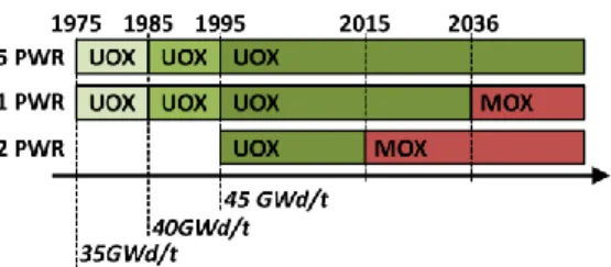
In the studied scenarios, the fleet is composed of 8 PWR of 900MWe each. Six of them are commissioned in 1975 and two in 1995. Between 1975 and 1995, the UOX fuels burn-up increases progressively from 35GWd/t to 45GWd/t. In 2015, two PWR are loaded with 30% of MOX fuel and in 2036 a third PWR is loaded with 30% of MOX fuels (Fig. 2).
Fig. 2. “MultiMOX PWR” - Scenarios chronology
The multirecycling of Pu in PWR MOX fuels is limited by an accumulation of Pu238 on the one hand and by an increase of the fresh fuel Pu content on the other hand. Reducing the fuel content in Pu241 allows to reduce the Pu238 creation (Pu241–Am241–Cm242–Pu238). Thus, to reduce the Pu238 content, it is necessary to reduce the Pu241 content and, to do so, to use Pu from old UOX fuels with a low burn-up (35GWd/t). On the contrary, Pu from UOX with a higher burn-up and a minimized cooling time has a higher Pu241 content that leads to a reduction of the Pu content in MOX fuels.
From this, two reprocessing strategies are proposed. The first one consists in the elaboration of the first MOX
fuels with Pu from UOX 35GWd/t to reduce its Pu238 content. The following MOX fuels are then elaborated with Pu from UOX 45GWd/t to reduce their Pu content. This strategy will be referred to as “scenario 1” and is described on Fig. 3. The second strategy consists in a mix of Pu from different UOX in appropriate proportions and will be referred to as “scenario 2”, described on Fig. 4.
Fig. 3. “MultiMOX PWR” - Scenario 1 - Reprocessing strategy
Fig. 4. “MultiMOX PWR” - Scenario 2 - Reprocessing strategy
In this article, “MOX 1” designates MOX fuels fabricated with Pu from UOX only. “MOX 2” stands for MOX fuels fabricated with Pu from UOX and MOX 1. “MOX 3” stands for MOX fuels fabricated with Pu from UOX and MOX 2.
III.B. Scenario results
The fuels fabrication flows are available on Fig. 5. The peaks correspond to the first cores fabrication and could be smoothed by anticipating the fabrication needs.
The PWR MOX fresh fuels thermal power is of about 445 W/assembly for MOX 1 and varies between 750 and 800 W/assembly for MOX 2 and MOX 3 (values similar to those of French standard MOX fuels).
The reprocessing flows associated to scenario 1 and scenario 2 are represented on Fig. 6 (scenario 1 left, scenario 2 right). In scenario 1, the old 35GWd/t UOX spent fuels (SF) are reprocessed first, whereas in scenario 2 old UOX and 45GWd/t UOX SF are reprocessed together. The efficiency of those strategies can be enhanced by reprocessing the old UOX in first-in-first-out mode and the more recent ones in last-in-first-out mode.
Fig. 6. “MultiMOX PWR” - Reprocessing flows
The evolution of the Pu isotopic content is represented on Fig. 7. The use of Pu from UOX spent fuels (SF) allows to compensate for the deterioration of the Pu in MOX fuels and to keep its fissile content above 60wt%. The change in the isotopic content in 2030 (resp. 2050) corresponds to the beginning of MOX 2 (resp. MOX 3) loading.
Fig. 7. “MultiMOX PWR” - Pu isotopic content (Scenario 1 in solid line, Scenario 2 in dotted line)
The fresh MOX fuels average Pu content is represented on Fig. 8. In scenario 1, the 9.65wt% limit is slightly exceeded as the Pu content reaches 9.93%. In both scenario, the Pu content stabilizes close to the 9.65wt% limit. It is noteworthy that, if UOX SF had been reprocessed in first-in-first-out mode without any reprocessing optimization, this limit would have been largely exceeded in 2035 (up to 13wt%).
Fig. 8. “MultiMOX PWR” - Pu content
The spent fuels (SF) storage is represented on Fig. 9 (scenario1 left, scenario 2 right). They are similar for both scenarios: the total SF storage (UOX+MOX) stabilizes at 5900tHM, including 16% of MOX SF. Note that, in comparison with a scenario in which no MOX SF would have been reprocessed, the MOX SF storage is reduced by 30%.
Fig. 9. “MultiMOX PWR” - Spent fuels storage
The evolution of the Pu inventory (Fig. 10) is similar for both scenarios and is increasing all along them. In 2100, it reaches 130tons, 0.6tons of which being Pu in waste. In comparison with an open cycle scenario (not represented on Fig. 10), in 2100 the Pu inventory is reduced by 25%.
Fig. 10. “MultiMOX PWR” - Pu inventory
III.C. Impact on waste management and final disposal The annual vitrified waste packages production (Fig. 11) is similar for both scenario and is of about 100 packages per year from 2035. As the limit on ray emission is never reached, the amount of produced packages depends on the oxide masse limit only.
Fig. 11. “MultiMOX PWR” - Waste packages annual production
The evolution of the toxicity by ingestion of waste cumulated all along the scenarios up to 2100 is represented on Fig. 12. The contribution of vitrified waste packages is separated from the one of the spent fuels stored in 2100. Results are compared to the ones of an open cycle scenario. Pu multirecycling leads to a reduction of the produced waste toxicity. After 10000 years of storage, the vitrified waste packages toxicity is reduced by a factor ten. However, the gain is not significant if the spent fuels toxicity is taken into account; multirecycling Pu in PWR changes the materials repartition between cycle and waste but does not impact the materials quantity. The same results are observed for the decay heat and the activity evolutions (Fig. 13).
On the Fig. 12 and Fig. 13, “VWP” stands for “Vitrified Waste Packages” and “SF” stands for “Spent Fuels”.
Fig. 12. “MultiMOX PWR” - Waste and SF toxicity by ingestion
Fig. 13. “MultiMOX PWR” - Waste and SF activity and decay heat
IV. Pu MULTIRECYCLING IN BOTH LWR AND SFR
IV.A. Efficiency and kinetic of Pu multirecycling in SFR Before studying the Pu multirecycling in both LWR and SFR, a preliminary study was conducted to evaluate the efficiency and the kinetics of Pu multirecycling in SFR. To do so, Pu vectors with different isotopic contents have been selected from the previous scenario and irradiated several time in a 600MWe SFR. Each time the Pu is irradiated up to 87GWd/t during 4x400 EFPD. The different Pu vectors come from the scenario 2 results and correspond to Pu in UOX, MOX 1, MOX 2 and MOX 3 spent fuels. They are detailed in TABLE III. The beginning date of this scenario, without any relevance here, is arbitrarily fixed at 2020.
TABLE III
“Pu multirecycling in SFR” - Initial Pu isotopic contents (%) UOX MOX 1.1 MOX 1.2 MOX 2 MOX 3
Pu238 2.65 3.50 3.01 3.72 3.54
Pu239 53.19 38.44 39.58 37.23 37.58
Pu240 25.79 34.50 34.51 34.61 34.78
Pu241 10.74 11.47 10.70 11.42 11.30
Pu242 7.63 12.09 11.30 13.02 12.80
“UOX”, “MOX1.1”… designate the SF from which the Pu is extracted.
“MOX 1.1”: firsts fabricated MOX 1. “MOX 1.2”: lasts fabricated MOX 1.
The evolution of the Pu isotopic content is detailed on Fig. 14. The Pu content in each isotope evolves by “steps”, the first step corresponding to the initial isotopic content (first load in core) and each following steps corresponding to an irradiation in SFR (following loads). Pu is therefore irradiated 4 times in SFR over the 60 years of life of the reactor (for each step, 7 years in core and 7 outside the core for fabrication and cooling). During the multirecycling in SFR, the Pu content in Pu241 decreases by 8% (in absolute deviation) whereas the one in Pu239 increases by 12% (absolute deviation). Note that the Pu238 content drops to 1% after 4 recyclings in SFR.
Fig. 14. “Pu multirecycling in SFR” - Evolution of Pu isotopic content
The evolution of the Pu fissile content is represented on Fig. 15. The recycling of Pu from MOX spent fuels leads to an increase in their fissile content. This process remains slow as the Pu fissile content increases by 5% in 60 years. However, the fissile content of Pu coming from UOX spent fuels is almost not impacted by the different recyclings in SFR.
Fig. 15. “Pu multirecycling in SFR” - Evolution of Pu fissile content
The evolution the thermal power and neutron sources of SFR fuels after being irradiated and cooled for 7 years is represented on Fig. 16 and Fig. 17. After 60 years of recyclings in SFR, the fuel thermal power is reduced by 30% if Pu came from UOX SF and 37% if it came from MOX SF. Its neutron sources are reduced by 26% (Pu from UOX SF) or 29% (Pu from MOX SF).
Fig. 16. “Pu multirecycling in SFR” - Thermal power
Fig. 17. “Pu multirecycling in SFR” - Neutron sources
Finally, one of the aims of this study is to evaluate the most efficient way to include a 600MWe SFR in the LWR fleet described in III. This SFR could be introduced at different points of the fleet, represented on Fig. 18: to increase the fissile content of Pu coming from UOX SF (position 1), MOX 1 (position 2) or MOX 2 (position 3).
Fig. 18. “Pu multirecycling in SFR” - Possibilities for the SFR introduction
The analysis of the Pu isotopic content evolution showed that the fissile content of a Pu coming from UOX SF is slightly impacted by successive irradiations in SFR. It also showed that the increase of the Pu fissile content of a Pu from MOX SF is a slow process. For those reasons, it appears that the best position for the SFR in the LWR is the position 2.
IV.B. Description of the scenario
After the study on the efficiency and kinetic of Pu multirecycling in SFR (IV.A), the following scenario is proposed:
- the LWR fleet is identical to the one studied in III; - in 2027 the SFR is loaded with Pu from MOX1
spent fuels;
- then, the SFR is loaded with Pu from both MOX and UOX SF;
- LWR are loaded with Pu from SFR and UOX spent fuels.
The objective of this symbiotic scenario is the reduction of the spent fuels storage (with a priority given to MOX spent fuels).
The hypothesis on LWR power plants and fuels are the same as the one considered for the study presented in part III. On top of that, the reprocessing to feed the SFR fuels fabrication is separated from the one to feed the LWR fuels fabrication. FR and LWR MOX spent fuels are reprocessed in dilution with UOX spent fuels and, up to 2050, the Pu / (Pu+U) ratio at reprocessing is limited to 2.2%.
The maximum Pu content of SFR fresh fuels is limited to 30%, which corresponds to an average content limited to 28.96%. As for the LWR fuels, limits on Pu238 and Am241 are also taken into account for the SFR fuels fabrication.
IV.C. Scenario results
The LWR needs in fabrication (Fig. 19) are the same as the ones of the LWR only scenario (III.B). The SFR fuels fabrication needs is of 7.5tHM/y.
Fig. 19. “MultiMOX SFR-LWR” - Fabrication flows
The reprocessing flows to feed the MOX fuels fabrication (Fig. 20) are identical to the ones of the scenario 2 (III.B) up to 2035. From 2035, LWR MOX fuels are fabricated with Pu from FR and UOX spent fuels. FR spent fuels represent 3.5% to 4.5% of the reprocessing flows. There dilution rate is about the same as the one of MOX spent fuels in the LWR only scenario.
Fig. 20. “MultiMOX SFR-LWR” - Reprocessing flows to feed the LWR MOX fuels fabrication
To avoid a peak at the beginning of the reprocessing to feed the FR fuels fabrication (due to the first core fabrication), the reprocessing starts 6 years before the beginning of FR fuels fabrication (Fig. 21). During those 6 years, only UOX SF are reprocessed; MOX SF starts in 2027. To respect the limit on Pu / (U+Pu) at reprocessing, MOX SF represent 20% of the reprocessing flow up to 2050 and 50% after. UOX spent fuels are reprocessed in first in first out mode to resorb the UOX 35GWd/t and UOX 40GWd/t spent fuels storages.
Fig. 21. “MultiMOX SFR-LWR” - Reprocessing flows to feed the SFR fuels fabrication
Finally, the Pu / (U+Pu) ratio for both reprocessing lines is represented on Fig. 22. It remains below 2.2% up to 2050.
Fig. 22. “MultiMOX SFR-LWR” - Pu flow at reprocessing
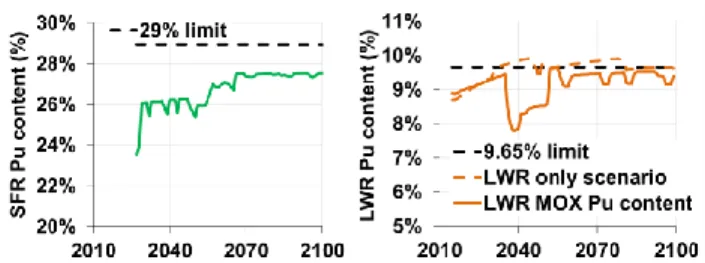
The SFR fresh fuels average Pu content is represented on Fig. 23 (left). It reaches a maximum of 27.6%, always below the limit of 28.96%. This indicates that the MOX SF reprocessing in SFR is limited by the constraints on reprocessing and by the MOX SF availability rather than by the constraints on FR fabrication.
The LWR MOX fresh fuels Pu content is represented on Fig. 23 (right). The introduction of a SFR in the LWR fleet and the Pu recycling in the SFR-LWR fleet leads to a slight decrease in the Pu content so that the 9.65wt% is never exceeded.
Fig. 23. “MultiMOX SFR-LWR” - Fresh fuels Pu content
The increase in the reprocessing flows linked with the introduction of an SFR in the LWR fleet leads to a reduction of the spent fuels storage (Fig. 24). By the end of the scenario, the total SF storage reaches 5500t, which represents a 25% reduction in comparison with the LWR only scenario. The increase in the MOX SF reprocessing leads to the stabilization of their storage at 120t. In comparison with the LWR only scenario, the MOX SF storage is reduced by 86% in 2100.
Fig. 24. “MultiMOX SFR-LWR” - Spent fuels storage (MOX storage stabilization)
It would have been possible to stabilize the total spent fuel storage (Fig. 25) by reducing the part of MOX spent fuel at reprocessing from 50% to 30%. In that case, the
UOX SF flow at reprocessing increases, which leads to a reduction of the UOX SF storage. The total SF storage stabilizes at 4800tHM but the MOX SF storage is no longer stabilized: it increases and reaches 200tHM in 2100.
Fig. 25. “MultiMOX SFR-LWR” - Spent fuels storage (total storage stabilization)
The Pu inventory (Fig. 26) is not impacted by the introduction of a SFR in the LWR fleet. It increases and reaches 128tons in 2100.
Fig. 26. “MultiMOX SFR-LWR” - Pu inventory
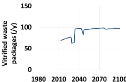
The annual production of vitrified waste packages is represented on Fig. 27. Unlike the LWR only scenario, at the beginning of MOX SF reprocessing to feed the SFR fuels fabrication, the limit is reached. This leads to an average production of 120 waste packages per year from 2050, representing a 10% increase in comparison with the LWR only scenario.
Fig. 27. “MultiMOX SFR-LWR” - Annual waste packages production
The toxicity of the waste cumulated during the scenario up to 2100 is represented on Fig. 28. The introduction of a SFR in the LWR fleet does not have a strong impact on it. The same results can be observed for the waste activity and decay heat (Fig. 29).
Fig. 28. “MultiMOX SFR-LWR” - Waste toxicity by ingestion
Fig. 29. “MultiMOX SFR-LWR” - Waste activity and decay heat
V. CONCLUSION
The study of Pu multirecycling in a LWR fleet shows that it is possible to recycle Pu in LWR MOX three times in a row. The decrease of the Pu fissile content is limited by mixing MOX SF and UOX SF at reprocessing so that the maximum Pu content in MOX fresh fuels remains below 11wt%. To do so, different reprocessing strategies have been assessed, ensuring a good level of flexibility of the scenario.
The Pu multirecycling in LWR leads to a reduction of the toxicity of the waste produced all along the scenario, up to 2100. Thus, after 10000y of storage, the waste toxicity is reduced by a factor 10. However, there is no meaningful gain anymore if the spent fuels toxicity is taken into account.
The impact of the introduction of a 600MWe SFR in the LWR fleet has been evaluated. The SFR is introduced to increase the fissile quality of Pu in LWR MOX fuels. A first study showed that the Pu enhancing in SFR is a slow process and is more efficient with Pu from MOX SF than with Pu from UOX SF. Thus, the SFR is introduced as soon as possible in the LWR fleet and is fed with as much Pu from MOX SF as the Pu / (U+Pu) limit at reprocessing allows it.
The reprocessing to feed the SFR fuels fabrication is separated from the one to feed the LWR MOX fuels fabrication. The amount of reprocessed MOX SF is increased and the UOX SF reprocessing strategy is simplified. The SFR Pu content is always below its 28.96% limit. The introduction of a SFR leads also to a slight reduction of the LWR MOX Pu content and allows to generate margins in the LWR cycle.
Finally, it is possible to reduce the spent fuels storage whether by stabilizing the MOX SF storage at 125tHM, or by stabilizing the whole spent fuel storage at 4800tHM. In the first case, the spent fuel storage is reduced by 25% in 2100 in comparison with the “PWR only” scenario. In the second, it is reduced by 34%.
The reprocessing of SFR SF leads to a 10% increase in the annual production of waste packages due to the reaching of the limit. The waste toxicity is, however, not impacted.
NOMENCLATURE EFPD Equivalent Full Power Day LWR Light Water Reactor PWR Pressurized Water Reactor
SF Spent Fuel
SFR Sodium Fast Reactor REFERENCES
1. C. COQUELET-PASCAL et al., “COSI6: A Tool for Nuclear Transition Scenarios Studies and Application to SFR Deployment Scenarios with Minor Actinides Transmutation”, Nuclear Technology, to be published. 2. R. ESCHBACH et al., “New Developments and
Prospects on COSI, the Simulation Software for Fuel Cycle Analysis”, Proc. of GLOBAL, Salt Lake City, US (2013).
3. L. BOUCHER, J.P. GROUILLER, “COSI: the Complete Renewal of the Simulation Software for Fuel Cycle Analysis”, Proc. of ICONE 14, Miami, USA (2006).
4. L. BOUCHER, J.P. GROUILLER, “COSI: a simulation software for a pool of reactors and fuel cycle plants”, Proc. of ICONE 13, Beijing, China (2005).
5. J.P. GROUILLER et al., “A Code for Simulating a System of Nuclear Power Reactor and Fuel Cycle”, Proc. of International Conference of Fast Reactors and Related Fuel Cycle, Kyoto, Japan (1991).
6. J.M. VIDAL et al., “CESAR5.3: an Industrial Tool for Nuclear Fuel and Waste Characterization with Associated Qualification”, Proc. of WM’12 Conference, Phoenix, USA (2012).
7. A. SANTAMARINA et al., “APOLLO2.8: a validated code package for PWR neutronics calculations”, Proc. of ANFM 2009, Hilton Head Island, USA (2009).
8. G. RIMPAULT et al., “The ERANOS code and data system for fast reactor neutronics analysis”, Proc. of PHYSOR 2002, Seoul, Korea (2002).