HAL Id: cea-02509673
https://hal-cea.archives-ouvertes.fr/cea-02509673
Submitted on 17 Mar 2020
HAL is a multi-disciplinary open access
archive for the deposit and dissemination of
sci-entific research documents, whether they are
pub-lished or not. The documents may come from
teaching and research institutions in France or
abroad, or from public or private research centers.
L’archive ouverte pluridisciplinaire HAL, est
destinée au dépôt et à la diffusion de documents
scientifiques de niveau recherche, publiés ou non,
émanant des établissements d’enseignement et de
recherche français ou étrangers, des laboratoires
publics ou privés.
Eschbach
To cite this version:
C. Coquelet-Pascal, M. Tiphine, G. Krivtchik, D. Freynet, R. Girieud, et al.. COSI6 : a Tool for
Nuclear Transition Scenarios Studies. GLOBAL 2015, Sep 2015, Paris, France. �cea-02509673�
COSI6: a Tool for Nuclear Transition Scenarios studies
C. Coquelet-Pascal1, M. Tiphine1, G. Krivtchik1, D. Freynet1, R. Girieud1, R. Eschbach1* 1
CEA, DEN, Cadarache, DER, SPRC, F-13108 Saint-Paul-lez-Durance, France. *[email protected]
Abstract – Nuclear systems, composed of reactors with varied fuel and cycle facilities (enrichment plant, fabrication
plant, reprocessing plant,…) are complex and in constant evolution. Decision makers need to have all the technical elements, based on dynamic nuclear fleet transition scenarios studies. These scenarios are tools to compare different options of nuclear systems evolution, and identify strengths and drawbacks. To have a complete overview of nuclear systems, it is required to follow precisely material flows at each step of the fuel cycle front-end and back-end, and at each date of the operation period. The evolution in time and under flux of materials isotopic composition has also to be taken into account, which can give access to other interesting values (activity, decay heat, toxicity,…).
Since 1985, CEA has been developing the COSI software, simulating in detail the evolution in time of a nuclear reactors fleet and its associated fuel cycle facilities. It is designed to study different options for the introduction of various nuclear reactor types and the use of the associated nuclear materials.
The general principle and the physical models of the current version in 2014 (COSI6 7.0) is described in the paper. The main physical models are the equivalence models in the fabrication plant, which determine the initial composition of mixed fuels in order to provide an equivalent efficiency whatever the isotopic composition of constitutive materials, and the depletion models for irradiated fuels in the core and cooling materials in storage: the reference model is CESAR of which several versions are available. CESAR is the reference code at the AREVA NC La Hague reprocessing plant and is used to calculate the isotopic composition of spent fuel by solving Bateman equation, using one-group cross sections libraries coming from neutronic codes (APOLLO2 in thermal spectrum and ERANOS in fast spectrum). An exercise of validation of COSI6 previously carried out on the French PWR historic nuclear fleet until 2010 (and not presented in this paper) allows us to validate the essential phases of the fuel cycle computation and highlights the credibility of the results provided by the code. Otherwise, a methodology of propagation of inputs uncertainties on results has been developed and could be implemented to quantify the uncertainties associated to scenarios results.
Finally, a methodology of optimization of scenarios is currently developed. It will consist in a module associated to COSI6, to find the appropriate input parameters defining the best scenarios for a given problem. Indeed COSI6 is a deterministic code in the sense that the scenario is simulated chronologically as function of the input parameters defined by the user, without any decision taken by the code. Nevertheless the user needs more and more often to identify solution scenarios to different problems (e.g. how to minimize natural resources consumption, waste production and toxicity) while respecting industrial constraints (maintaining the energy production, limiting the interim storages, stabilizing the plants capacities,…).
I. INTRODUCTION
Nuclear systems, composed of reactors with varied fuels and cycle facilities (enrichment plant, fabrication plant, reprocessing plant …) can be really complex. To have a complete overview of nuclear systems, it is required to follow precisely material flows at each step of the front-end and the back-front-end fuel cycle and at each date of the operation period. Due to the specificities of radioactive materials, the evolution in time and possibly in pile irradiation of materials isotopic composition has to be taken into account. That can give access to other
interesting values (activity, decay heat, toxicity …) as regards the operation and safety of nuclear facilities.
Since 1985, CEA (Nuclear Energy Division – DEN) has been developing a nuclear systems software simulating in detail the evolution in time of a nuclear reactors fleet and the associated fuel cycle facilities, called “COSI” [1]. COSI is designed to study different options for the introduction of various types of nuclear reactors and the use of associated nuclear materials. The main publications and examples of applications are given in references [1] to [10].
COSI uses CESAR [11] software to calculate the isotopic composition of all materials, in each point of the nuclear cycle and at any time.
The current version is COSI6 V7.0. A new version of COSI (COSI6 V8.0) being under development.
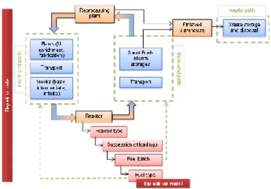
Figure 1 shows the global operation of COSI6 based on the annual energy demand. From the energy demand and knowing the reactors and fuels characteristics, fuels fabrication and materials needs are determined. Material flows in the cycle front-end and the back-end are followed during the simulation. The reprocessing plant can be used to close the fuel cycle, with a possible evaluation of waste production.
Fig. 1. COSI6 flow scheme.
Several physical models are used in COSI6 and are detailed in this paper. The main ones are the following: - Depletion models inside the core but also for cooling materials in storage. The reference model is CESAR, of which several versions are available.
- Equivalence models in the fabrication plant, to determine the initial composition of mixed fuels to provide an equivalent efficiency whatever the isotopic composition of constitutive materials.
Parts 2 and 3 of this paper present how to install and launch COSI6, as well as a focus on the Graphical User Interface. Part 4 gives an overview of a simulation. Part 5 details the depletion code CESAR, and part 6 the equivalence models.
Part 7 describes the post-processing tools included in COSI6. Part 8 gives references of the exercise of validation of the code on the French PWR historic nuclear fleet.
Finally, parts 9 and 10 describe developments of COSI6 that are still on the ground, and including the propagation of inputs uncertainties, and a scenario optimization methodology.
II. INSTALLATION OF COSI6
COSI6 and CESAR softwares operate on LINUX systems.
A 15 Go random access memory (RAM) is convenient for usual applications. The necessary RAM to run simulations depends on the number of reactors, the level of heterogeneity of reactors, the duration of the simulation and the amount of isotopes taken into account (depending on the CESAR version, see 4.3.1).
The current COSI6 version requires java version 1.6. COSI6 is available through a license agreement; Current owners are ENEA (Italy), KIT (Germany), VTT (Finland) and different French Institutes.
III. GRAPHICAL USER INTERFACE
Standard COSI6 utilization is made by a graphical user interface which represents a data set in the form of a tree and a set of simulations, included in a project. It also provides tools for the simulation data treatment.
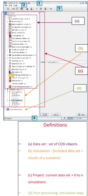
Fig. 2. COSI6 graphical user interface.
1 2 3 4 (a) (b) (c) (d)
Definitions
– (a) Data set : set of COSI objects
– (b) Simulation : [included data set + results of a scenario]
– (c) Project: current data set + 0 to n simulations
– (d) Post-processing: simulation data treatment
The main window of the COSI6 code is composed of several task bars at the top and the bottom of the window. 1) Title bar: provides information on the COSI6 code version and the project file name. The title bar is used to move, restore, shrink, enlarge and close the main window. 2) The menu bar: used to access different actions classified by category:
- File: groups the actions related to projects and simulations files (exportation, …).
- Editing: groups all editing actions.
- Tools: groups tools to facilitate the elaboration of
the data set.
- Help: provides both information on the COSI6
code and help.
3) The tool bar: used to quickly access the most frequent actions. This floating tool bar is designed so that the user can place it on any four edges of the main window or completely detach it.
4) The status bar: provides three types of information: - Left panel: project status (open, changed, saved,
etc.); a project includes the job and one or several simulations
- Centre panel: abridged help on the tool bar
buttons;
- Right panel: occupied memory and available
memory, JAVA garbage collector.
COSI6 graphical user interface is able to read and write specific inputs/outputs files:
- Inputs: from the file system to COSI
o Importation of a data set object
(.xml),
o Importation of a simulation,
o Opening a project,
o Reading cross section libraries and
CESAR data,
o Reading CESAR results.
- Outputs: from COSI to the file system
o Exportation of a data set object,
o Exportation of a simulation,
o Saving a project,
o Saving postprocessed results,
o Writing an archive file,
o Writing CESAR input.
IV. OVERVIEW OF THE CODE
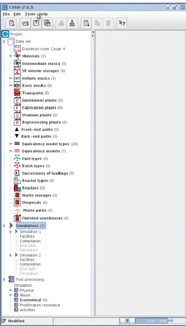
IV.A. Data Set
There are three kinds of objects:
- Selectable facilities (which drive the simulation
and have to be selected before running the simulation) in orange in Figure 3:
o Reactors,
o Reprocessing plants, o Finished warehouses.
- Other facilities (passive operation) in blue in the next figure:
o Stocks (intermediate / infinite / basic), o Spent fuels interim storages,
o Transports,
o Plants (enrichment / fuel fabrication / uranium),
o Waste storages and disposals.
- Other objects linked to facilities, which define
their operation,(in green in the figure 3): o Depletion code,
o Materials (isotopic composition), o Front-end and back-end paths,
o Equivalence model types / equivalence models,
o Fuel types / batch types, o Succession of loadings, o Reactor types,
o Waste paths.
IV.B. Overview of a simulation
COSI6 is a software simulating the evolution in time of material fluxes in a nuclear reactors fleet and its associated fuel cycle facilities.
In a COSI6 data set, various elements are available to describe a nuclear reactors fleet:
- Reactors,
- Different types of plants:
o uranium [conversion or extraction] plant, o enrichment plants,
o fabrication plants, o reprocessing plants.
- Material stocks which can be of different types: basic stocks, intermediate stocks and infinite stocks (that can provide an infinite quantity of material, for example infinite natural Uranium stock or infinite Pu stock ; infinite stocks are useful and may be used to feed a fabrication plant without constraint on the material quantity or to quantify a lack of fissile materials),
- SF (Spent fuels) interim storages,
- Transports,
- Waste facilities :
o finished warehouses, o waste storages and disposals.
Fig. 3. COSI6 data set in the GUI
Relations between these facilities can be defined with others objects of the data set:
- The front-end path is used to define the path of materials upstream of the reactor. A front-end path can take into account plants (uranium plant, enrichment plant and fabrication plant), transports and stocks. A front-end path is associated with a fuel type (the fabrication of different fuel types cannot be modelled in the same front-end path).
Fig. 4. Example of front-end path for UOX fuel
- The back-end path is used to define the path of materials downstream of the reactor. A back-end path can take into account SF interim storages and transports.
Fig. 5. Example of back-end path with two SF interim storages. - The waste path is dedicated to the definition of
the path of materials in waste facilities (SF interim storages, waste storage and disposal). A waste path contains necessary a finished warehouse (transformation of waste materials into packages), characterized by a commission date (and final shutdown date), an operation time, a conditioning type (vitrification, conditioning, compaction,..), a package mass (t/package) and a
package volume (m3/package), a maximum
material mass (tons/package) corresponding to the maximum mass of Fission Products and Actinides per package. The isotopic composition of materials can be taken into account, as well as additional constraints (alpha radiations of waste) to restrict the fabrication.
To complete a data set, it is required to define the reactor loading and unloading steps. To do this, the following objects are used:
- Fuel types to define the physical properties of a
fuel (always associated to a front-end path). The fuel type is fundamentally linked to an equivalence model (cf. §VI). Fuel type are characterized in particular by a calculation tool for the depletion calculation in core, which can be CESAR, ERANOS, or Final imposed content; CESAR is the standard way, and the user has to define CESAR library number (BBL) and spectrum (thermal or fast). ERANOS is reserved to SFR fuels [5]. Final imposed content is useful for fuel with constant initial composition and constant final composition. Fuel types are also characterized by the enrichment in 235U or Pu mass content, burn-up, equivalence model. - Fuel batches to define batches of fuels composed
of one or more fuel types (always associated to a back-end path). A batch type represents a set of fuel sub-assemblies, which can be homogeneous (one fuel type in one batch type), or heterogeneous (several fuel types in one batch type). Minimum cooling time before reprocessing and transport can be defined, as well as (CESAR5.1 or 5.3 only) criteria on the maximal decay heat of the fuel assembly before transport or reprocessing.
- A succession of loadings to define the history of the mass of fuel batches to load in a reactor.
- A reactor type to define common characteristics
for a set of reactors: electric power, operating profile, yield (ratio between electrical and thermal power) and succession of loadings. A reactor type is always associated to a reactor. A reactor can represent one or several nuclear power plants
producing electrical energy in a COSI6
simulation. A reactor is characterized by commissioning and final shutdown dates, and a time dependent load factor.
The remaining objects of the data set can be considered as elements to complete the data set:
- Depletion code choice, to select the code used to
perform the evolution of the materials
composition during the simulation. The depletion code is used in every facility at any time.
- Materials: the isotopic composition of materials
is one of the results of the simulation. Nevertheless, it is possible to define isotopic composition of materials, used for specific applications in the data set (initialization of stocks with a given material, definition of fuels with fixed composition …).
- Equivalence model: the physical model used to
evaluate the fresh fuel composition (always associated to a fuel type).
The links between the different objects of a data set are summarized on the next figure.
Fig. 6. Operating diagram of a COSI6 data set.
Once a complete data set has been created, a scenario simulation can be launched.
V. DEPLETION CODE
V.A. CESAR
CESAR means “Simplified Evolution Code Applied to
Reprocessing”. COSI6 can be coupled with 4 versions:
CESAR4, CESAR5.1, CESAR5.3 and CESAR5.3 HN
(Heavy Nuclides). All the versions use one-group energy
cross sections libraries. CESAR5.3 is the reference code at the AREVA NC La Hague reprocessing plant and is used to calculate the isotopic composition of spent fuel. CESAR5.3 is validated by comparison with the reference CEA depletion code (DARWIN) and is qualified with experimental data. The use of CESAR5.3 [11] is recommended.
COSI6 coupled with CESAR4 is restricted to the evaluation of 21 isotopes of U, Np, Pu, Am, Cm:
- U232, U234, U235, U236, U238 ;
- Pu236, Pu238, Pu239, Pu240, Pu241, Pu242 ;
- Np237, Np239 ;
- Am241, Am242M, Am243 ;
- Cm242, Cm243, Cm244, Cm245, Cm246.
The mass of fission products is taken into account in a macro-isotope called FP_wastes. For historical reasons, some long life fission products (I, Tc, …) are partially evaluated if COSI is coupled with CESAR4. It is not recommended to take into account these results, knowing that the fission products evaluation is not complete (a lot of fission products are missing).
When COSI6 is coupled with CESAR4, a simplified depletion module is used for cooling calculation. This depletion module is designed to perform calculation for evolution time lower than 1000 years. If a detailed calculation of fission products is required (to characterize spent fuels for example), COSI6 has to be coupled with CESAR5.
The main difference between CESAR5.1 and CESAR5.3 is the origin of nuclear data: CESAR5.1 uses nuclear data from JEF2 whereas CESAR5.3 uses nuclear data from JEFF3.1.1.
COSI6 coupled with CESAR5.1 or 5.3 takes into account 109 heavy nuclides (Tl → Cf) and more than 200 fission products. Consequently, the calculation time is significantly higher with CESAR5 by comparison with CESAR4. Calculation with COSI6 coupled with CESAR5 also requires more RAM and leads to heavier simulations. To limit those problems, a new calculation procedure has been added: COSI6 coupled with CESAR5.3 HN (CESAR5.3 restricted to the 109 Heavy Nuclides). As for CESAR4, fission products are taken into account in a macro-isotope called Macro_FP (only the global mass of fission products is evaluated) and a depletion module (with functionalities equivalent to CESAR5.3) is used for cooling calculation.
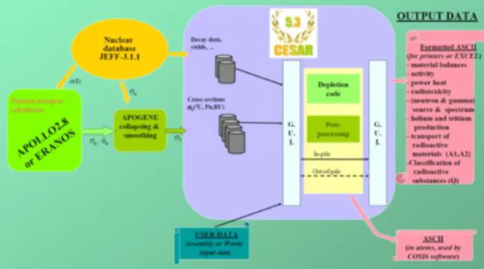
V.B. Generation of cross sections libraries
APOGENE software generates one group cross section libraries using data (multi-group cross sections and neutron flux) in a specific data frame, coming typically from APOLLO in thermal spectrum or ERANOS in fast spectrum. Those data are completed with nuclear data
coming from various databases depending on the version of CESAR. See Figure 7 for a data flow scheme.
Fig. 7. CESAR5.3 data flow scheme.
Cross sections libraries contain one-group cross sections tabulated in function of burn-up and of specific parameters for each fuel type. We can quote initial 235U enrichment for UOX fuel, and initial Pu content and Pu isotopic composition for MOX fuel. The validity domain of each library extends over limited ranges of fresh fuel composition and irradiation characteristics (burn-up, irradiation power …). Consequently, a CESAR cross sections library is adapted for a given fuel type in a given reactor type and cannot be used for a different fuel or outside its validity domain. The range of validity of each parameter of a CESAR library are given in control text file (same number than the library).
Finally, cross sections values are encrypted in the library file (the values readable in the file do not correspond to cross sections values).
More than 60 libraries are available in CESAR4.39 covering the diversity of the reactors (PWR, SFR, ADS, HTR, ..), and about 20 in CESAR5.3.
VI. EQUIVALENCE MODEL
An equivalence model type is a calculation method that, when associated with a set of parameters (modifiable or not), evaluates the initial composition of a fuel, based on the isotopic content of the available materials, to ensure an equivalence in terms of fuel efficiency (for example, to reach a given burn-up or a given isotopic enrichment) and to ensure the core criticality.
COSI6 counts 10 types of equivalence models, without any possible interaction of the user: PWR MOX, MOX_UE_RMA (enriched uranium support with high moderation ratio), MOX_UE_RMA_RVL, SFR_PU, SFR_GEN4, SFR_GEN4B, HTR_PU (High Temperature Reactor), CORAIL (PWR sub-assembly with MOX and UOX rods), APA (Advanced Plutonium Assemblies with annular rods in PWR), URT (Enriched Reprocessed
Uranium). The addition of a new calculation method requires a development.
An equivalence model is composed of a set of coefficients that, when associated with an equivalence model type corresponding to a calculation method, calculates either the content of an element or the isotopic enrichment of an element required to ensure an equivalence in terms of fuel efficiency. This content or enrichment is calculated based on the isotopic composition of the different elements composing the fuel assembly. Certain equivalence models also make it possible to choose automatically a specific CESAR library.
The general principle of equivalence model is described in Figure 7. The definition of the set of coefficients used in the equivalence model relies on previous neutronic calculation of the fuel in core, which can be for example performed with APOLLO 2 in thermal spectrum or ERANOS in fast spectrum. Other data read during the simulation or defined by the user in the data set are also used by the equivalence model. The final result is the fresh fuel composition.
A key point is the fact that a validity domain in terms of fresh fuel composition and irradiation characteristics is associated to each equivalence model, as illustrated in [5]. Consequently, an equivalence model is adapted for a given fuel type in a given reactor type and cannot be used for a different fuel or outside its field of validity (as it is the case of CESAR library).
Fig. 7. General principle of equivalence models.
VII. POST-PROCESSING
A simulation post-processing can be carried out after the simulation calculation or at a later date by importing a simulation. The post-processing involves calculating the materials flows between the different simulation stations and evaluating physical features characterizing the materials.
The following types of post-processing (PP) operations can be distinguished:
- Physical PP: balance (for any given facilities, the
balance presents all the annual inputs/outputs, cumulative inputs/outputs), or status (all the materials contained in a facilities, evaluated at date X);
- Waste PP, dedicated to waste characterization.
This PP evaluates the packages number, the total mass of packages, the total volume of packages,
Set of coefficients produced with
previous neutronic transport calculation (APOLLO2, ERANOS)
Data from the simulation Materials isotopic composition
Parameters from the data set Reactor types
Fuels types and characteristics (BU, fractionation …)
Equivalence model
Results: fresh fuel composition U235 enrichment
Mass Pu content
the thermal power, the activity and the toxicity of packages and the facilities area. The calculation of packages number depends on the packages characteristics defined in the data set. Activity (TBq), toxicity (TSv) and thermal power (W) of all the packages are calculated by CESAR from the isotopic composition of packages on the specified time period;
- Economical PP. This PP can be used to evaluate
economical aspects of a nuclear reactor fleet simulation: annual expenditure for investment, operation, transport, dismantling … The use of
this economical post-processing requires
economical inputs data (unit costs …). It is the responsibility of the user to define those data;
- Proliferation resistance PP. This PP evaluates
several indicators based on the Charlton method (it is important to keep in mind that the application of Charlton method is not complete in this post-processing. This post-processing gives only access to proliferation resistance indicators based on the formalism developed in the Charlton method) :
o heating rate from Pu (W/kg),
o weight fraction of even Pu isotopes (%), o inventory of fissile material (Significant
Quantity, SQ),
o concentration of fissile material (SQ/t), o radiation dose rate (rem/h/SQ),
o partial proliferation resistance measure resulting from an aggregation of utility functions: PRP.
- Activities PP. This PP evaluates the thermal
power, the activity, the toxicity and the neutron sources of materials in cycle. Activity (TBq), toxicity (TSv), thermal power (W) and neutrons sources (neutrons/s) are calculated by CESAR from the isotopic composition of materials on the specified time period. Toxicity by ingestion and toxicity by inhalation are both evaluated. The evaluation of activity, toxicity, thermal power and neutrons sources for materials in the back-end cycle (spent fuels in storages or at the reprocessing plant…) is correct only if CESAR5.1 or CESAR5.3 is used, with a complete evaluation of heavy nuclides and fission products.
- Strategic material PP. In the future version COSI6
V8.0, a new post-processing called « Strategic material » will be added. It consists in a first approach to follow non nuclear materials in cycle. It could be useful to evaluate the mass of building materials, the mass of coolant … The activation of those materials would not be taken into account. The quantity of those materials would be estimated by proportions with the number of working reactor or the mass of loaded fuels [10].
VIII. VALIDATION OF COSI
An exercise of validation of COSI6 has been carried out on the French PWR historic nuclear fleet until 2010 to validate the essential phases of the fuel cycle computation: cumulative Natural Uranium consumption, cumulative SWU for Enriched Uranium, stocks of Reprocessed Uranium, Pu inventory in cycle and waste, total quantity of spent fuel to store. This validation highlights the credibility of the results provided by the code [10].
IX. PROPAGATION OF INPUTS UNCERTAINTIES
Several sources of uncertainty have an impact on the scenario results, such as nuclear data and industrial parameters. Nuclear data uncertainties propagate in the scenario along the isotopic chains through depletion, cooling and fuel equivalence models, while industrial parameters impact directly the fuel cycle facilities, such as the reprocessing plant plutonium and minor actinides recovery rates or the spent fuel burnup. A method dedicated to uncertainty propagation in scenario studies based on a Monte-Carlo approach and surrogate models was developed [12, 13] and implemented in COSI.
The method relies on depletion surrogate models in order to calculate the spent fuel composition in every depletion computation in a scenario. Surrogate models estimate the concentration of 19 actinides and 15 fission products in spent fuel. Those models also manage nuclear data so that nuclear data uncertainty propagation is possible, and must be supplied with energy-integrated fission and capture cross-sections perturbations, as well as fission yields perturbations. The estimators, composing the surrogate models, are constructed as artificial neural networks, an estimator structure that allows modeling non-linear function of several interacting parameters. The implementation of this sub-model approach in the new COSI scheme provides a speedup superior to 500, thus allowing stochastic uncertainty propagation computations on complex scenarios.
X. METHODOLOGY OF OPTIMIZATION OF
SCENARIOS
COSI is currently simulating chronologically, without decision making, scenarios whose parameters are fully defined by the user. As the interactions among reactors and fuel cycle facilities can be complex, and the ways in which they may be configured are many, the development of stochastic optimization methodology could improve scenario studies. The optimization problem definition needs to list relevant criteria against which scenarios can be discriminated, variables which are some scenario parameters related to reprocessing, reactor functioning,
etc., and constraints making scenarios industrially feasible. The future French nuclear fleet must meet numerous and often conflicting aims of interest for different stakeholders such as saving natural resources, reducing electricity generation cost and minimizing nuclear waste. The high number of scenario calculations needed to solve an optimization problem can be time-consuming and hardly achievable, and so requires reducing the COSI computation time. Given that CESAR evolution calculations represent about 95% of the COSI computation time, CESAR surrogate models have been built, like for uncertainty propagation studies, and coupled with COSI. Coupling the new COSI scheme using surrogate models with
optimization method enables optimal parameters
estimation for a given strategic probem. Works concerning the development of this methodology of optimization are presented in [14].
XI. SCENARIOS STUDIES
In the frame of the 2006 French Act for waste management, scenario studies have been carried out with COSI, to compare different options of evolution of the French reactor fleet and options of partitioning and transmutation of plutonium and minor actinides. These studies aim in particular at evaluating the sustainability of Sodium cooled Fast Reactors (SFR) deployment and the possibility to transmute minor actinides [4, 6, 7, 8, 9]. These studies lead the CEA, EDF and AREVA to work together on progressive potential scenarios of the French transition between the current nuclear fleet and a SFR fleet which does not require natural uranium to operate [15]. Other studies have been recently done with COSI [16], concerning multi-recycling of Pu in PWR MOX and SFR.
XII. CONCLUSION
This paper gives an overview of the COSI6 code, as well as the developments planned in a short term. In particular, the evaluation of the uncertainty’s impact on scenario’s results is a major stake for the scenario codes in the future. In addition, the development of a multi-objective optimization capability around the COSI nuclear fuel cycle simulation code, will allow for the automated determination of optimum deployment scenarios and objective trade-off surfaces for dynamic fuel cycle transition scenarios.
REFERENCES
1. L. Boucher, J.P. Grouiller, “COSI: a simulation
software for a pool of reactors and fuel cycle plants”,
Proceedings of ICONE 13, Beijing, China (2005). 2. L. Boucher, J.P. Grouiller, “COSI: the complete
renewal of the simulation software for the fuel cycle
analysis”, Proceedings of ICONE 14, Miami, Florida,
USA (July 17-20, 2006).
3. M. Meyer, L. Boucher, “New Developments on COSI6,
the Simulation Software for Fuel Cycle Analysis”,
Proceedings of Global 2009, Paris, France (September 6-11, 2009).
4. C. Coquelet et al. “Comparison of Different Options
for Transmutation Scenarios Studied in the Frame of the French Law for Waste Management”, Proceedings
of GLOBAL 2009, Paris, France (September 6-11, 2009).
5. C. Coquelet-Pascal et al. « Validation of Physical
Models Used in Scenarios Studies by Coupling COSI with ERANOS Package”, Proceedings of GLOBAL
2011, Makuhari, Japan (December 11-16, 2011). 6. C. Coquelet-Pascal and C. Kieffer, “Comparison of
Different Scenarios for the Deployment of Fast Reactors in France – Results Obtained with COSI”,
Proceedings of GLOBAL 2011, Makuhari, Japan (December 11-16, 2011).
7. C. Coquelet-Pascal et al., “Some Scenarios for Minor
Actinides Transmutation in the Frame of the French Act for Waste Management”, Proceedings of IEMPT
2012, Prague, Czech Republic (September 24-27, 2012).
8. C. Coquelet-Pascal et al., “Scenarios for Fast Reactors
Deployment with Plutonium Recycling”, Proceedings
of Fast Reactors Conference, Paris, France (March 4-7, 2013).
9. M. Meyer, M. Tiphine et al., “Scenarios for Minor
Actinides Transmutation in the Frame of the French Act for Waste Transmutation”, Proceedings of Fast
Reactors Conference, Paris, France (March 4-7, 2013). 10. R. Eschbach et al., New developments and Prospects
on COSI, the simulation software for fuel cycle analysis, GLOBAL 2013, Salt Lake City, USA (2013).
11. J.M. Vidal et al., « CESAR5.3 : an Industrial Tool for
Nuclear Fuel and Waste Characterization with Associated Qualification », Proc. of WM’12
Conference, Phoenix, Arizona, USA (2012).
12. G. Krivtchik et al., Analysis of uncertainty
propagation in scenario studies: application to the French historical PWR fleet, GLOBAL 2015, Paris
(2015).
13. G. Krivtchik et al., “Development of Depletion Code
Surrogate Models for Uncertainty Propagation in Scenario Studies”, Supercomputing in Nuclear
Applications and Monte Carlo 2013 (SNA + MC 2013), Paris.
14. D. Freynet et al., Multiobjective Optimization for
Nuclear Fleet Evolution Scenarios using COSI,
GLOBAL 2015, Paris (2015).
15. M. Tiphine et al., Industrial scenarios of Pu
multirecycling in SFR and associated phase-out,
16. M. Tiphine et al., Sodium Fast Reactor: an asset for a
![[PDF] C'est quoi le trading en ligne pdf cours | Formation Forex](data:image/gif;base64,R0lGODlhAQABAIAAAP///wAAACH5BAEAAAAALAAAAAABAAEAAAICRAEAOw==)