HAL Id: hal-02520891
https://hal.archives-ouvertes.fr/hal-02520891
Submitted on 27 Mar 2020
HAL is a multi-disciplinary open access
archive for the deposit and dissemination of
sci-entific research documents, whether they are
pub-lished or not. The documents may come from
teaching and research institutions in France or
abroad, or from public or private research centers.
L’archive ouverte pluridisciplinaire HAL, est
destinée au dépôt et à la diffusion de documents
scientifiques de niveau recherche, publiés ou non,
émanant des établissements d’enseignement et de
recherche français ou étrangers, des laboratoires
publics ou privés.
Interface failure in nacre-like alumina
Ronan Henry, Hassan Saad, Aurélien Doitrand, Sylvain Deville, Sylvain Meille
To cite this version:
Ronan Henry, Hassan Saad, Aurélien Doitrand, Sylvain Deville, Sylvain Meille. Interface failure in
nacre-like alumina. Journal of the European Ceramic Society, Elsevier, 2020, 40 (13), pp.4694-4699.
�10.1016/j.jeurceramsoc.2020.05.068�. �hal-02520891�
Interface failure in nacre-like alumina
Ronan Henry
a, Hassan Saad
b, Aurélien Doitrand
a, Sylvain Deville
b, c, Sylvain Meille
a*aUniversité de Lyon, INSA Lyon, MATEIS UMR CNRS 5510, 7 avenue Jean Capelle, 69621 Villeurbanne, France bLaboratoire de Synthèse et Fonctionnalisation des Céramiques, UMR 3080 CNRS/Saint-Gobain, Saint-Gobain Research Provence, Cavaillon, France c now with: Université de Lyon, Université Claude Bernard Lyon 1, CNRS, Institut Lumière Matière, 69622 Villeurbanne, France * Corresponding author: [email protected]
Abstract
Among many bioinspired materials contenders, ceramic-ceramic composites based on alumina platelets have recently emerged as a new class of strong and damage-resistant materials. These materials are brick-and-mortar composites, where bricks are single-crystal alumina platelets, and a glassy interphase acts as the mortar. Although several processing approaches have been reported to date, these materials were optimized so far by trial-and-error approaches. Understanding the fracture properties of nacre-like alumina requires the knowledge of the properties of each of its components. However, only the properties of alumina platelets have been evaluated so far. Here we characterize at a micro scale the fracture property of an aluminosilicate glass interphase between alumina platelets. Micro-cantilever specimens prepared by FIB milling are tested under bending in order to characterize the failure of interfaces exhibiting orientations between 0° and 90° with respect to the beam direction, and thus undergoing different combined shear and tensile stress. Failure appears to be mainly driven by the interface opening stress that seems to predominate over shear stress. The apparent fracture stresses vary from 0.5 GPa to 3.0 GPa depending on the interface angle. It results in a maximum opening stress of 0.72 ± 0.18 GPa reached locally at the interface, whereas the apparent tensile fracture stress of a pack of aligned and perpendicular platelets is approximately 3 GPa. These results should help understand the bulk properties of nacre-like alumina composites and future similar materials and enable a rational design of their components and microstructures.
1.
Introduction
Architectured natural materials show a complex microstructure which leads to efficient mechanical properties [1]. For instance, natural nacre has been widely studied [2] and led to the development of many types of bio-inspired materials [3][4]. The availability of micrometer-sized alumina platelets have recently led to the development of nacre-like alumina, a new family of ceramic-ceramic composites [5]. Nacre-like aluminas combine several properties rarely achieved simultaneously on monolithic materials [6][7]. Due to its specific microstructure involving only mineral components, this ceramic-ceramic composite combines high stiffness and good thermal stability with a high fracture toughness. Its brick-and-mortar microstructure is made of high-strength alumina platelets (bricks) aligned in a preferential direction and separated by a secondary glassy phase that acts as a mortar. The alignment of platelets can be achieved by various processes, such as freeze-casting [8] or magnetic assisted slip casting [9]. Recently, it has also been shown that the simple use of unidirectional pressure during sintering allows the platelets to be aligned perpendicularly to the direction of the load [10][11]. As interfaces between platelets are more favorable to the crack propagation than alumina grains, cracks are deflected along interfaces. This dissipates more energy than a straight crack path, and thus increases the apparent fracture toughness of the material.
The macroscopic mechanical properties of a nacre-like material are dependent on the properties of its constituents, i.e. the platelets and their interfaces. However, the individual fracture properties of these constituents are difficult to measure because of their small size. Recently, micromechanical bending tests have been used to evaluate the strength of a single alumina platelet [12]. These experiments are valuable to improve the optimization of the material macroscopic properties, but the study of the interface properties is just as important, since the crack path follows these interfaces. For example, for a nacre-like alumina with an aluminosilicate glass-phase (composition SiO2 : Al2O3 : CaO (65 :25 :10 in
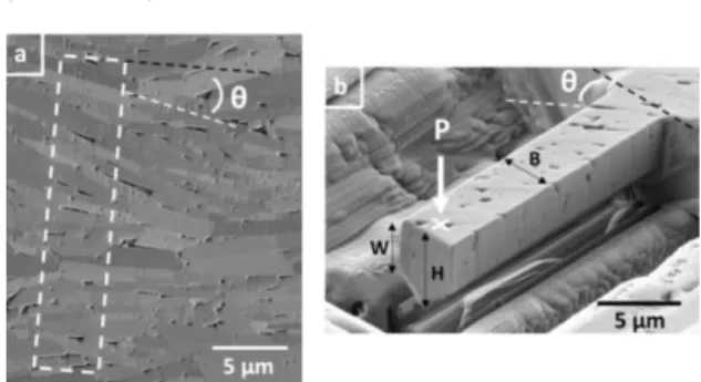
%wt)) and for macroscopic tests performed on single-edge notched beams (SENB) [11], cracks are systematically initiated on interfaces at about 75° from the notch axis (
F
IGURE1
-
A
) and propagate along the interfaces, bypassing the platelets (F
IGURE1 - B
).Figure 1 : Nacre-like alumina: (a) optical micrograph of a notch tip after the SENB specimen failure, with an important crack deflection from the notch; (b) SEM image of a fracture surface. The arrow indicates the direction of crack propagation.
© (2020) R. Henry et al. (10.6084/m9.figshare.11999985) CC BY 4.0 license https://creativecommons.org/licenses/by/4.0/.
Here we characterize at a microscopic scale the property of individual interfaces constituted of an aluminosilicate glass-phase to understand the fracture behavior of nacre-like alumina ceramics. Platelets have a hexagonal shape with micrometer dimensions (0.5 µm thickness, 10 µm diameter). The thickness of the glass interphase is as small as a few nanometers. Because of these small dimensions, the micro-cantilever bending method [13] was chosen and applied to evaluate the fracture properties of interfaces between alumina platelets.
2. Materials and methods
A nacre-like alumina sample, with the same composition as in [5] was prepared as described in [11]. A slurry composed of alumina nanoparticles (TMDAR, TaiMei, diameter about 100 nm) and glass phase precursors (colloidal silica Nexsil 20K30 from Nyacol and calcium carbonate from Sigma-Aldrich), used respectively for the formation of the mineral bridges and the glass-phase at the interfaces between the platelets, was firstly prepared in deionized water. The system was then mixed by ball-milling with alumina media for 23 hours. Micrometer-sized alumina platelets (Ronaflair® White Sapphire, Merck, Kenilworth, USA) were added for the last three hours only to avoid extensive fracture of platelets during milling. The slurry was then immerged in liquid nitrogen for 15 min and freeze-dried for 72 h (Freezone 4.5, Labconco, USA). The resulting powder was heat treated up to 900°C to burn off all organic components. The dry powder obtained was composed of alumina platelets covered by the precursors of the glassy phase and alumina nanoparticles.
The powder was then sintered with field-assisted sintering in a graphite die at 1450°C for 15 min and under a 40 MPa uniaxial pressure. During the heating-up, the pressure was 20 MPa and the heating rate was 100°C/min. The pellet was then cooled at 100°C/min down to room temperature with no load applied. The resulting sample had a density of 98% and a negligible grain growth, the platelet size remained close to their initial dimensions (
F
IGURE2 - A
).Figure 2 : SEM image of (a) an example of pre-selected area where the cantilever can be prepared, (b) a micro-cantilever prepared by FIB, with an angle θ between platelet interfaces and the beam axis. The white arrow indicates where the load was applied for mechanical testing. © (2020) R. Henry et al. (10.6084/m9.figshare.11999985) CC BY 4.0 license https://creativecommons.org/licenses/by/4.0/.
The pellet was cut with a micro-slicer to obtain a sample with millimeter dimensions and the shape of a parallelepiped. This sample was glued on a stub, the upper face perpendicular to the preferred orientation axis of platelets. The sample surface was then polished with diamond suspensions from 9 µm size down to 1 µm size, followed by vibratory polishing using a 0.03 µm colloidal silica suspension (
F
IGURE2 - A
). In order to avoid charging effects under microscope beam, the sample was coated with a carbon layer of about 10 nm thick and the unpolished surfaces were covered with silver paint.Micro-cantilever specimens were prepared using a Focalized Ion Beam (FIB) (NVision40, Carl Zeiss, Oberkochen, Germany), with a pentagonal section and typical dimensions around 4x4x20 µm3 (
F
IGURE2 - B
).Gallium ions were used at an accelerating voltage of 30 kV to perform the milling. The first preforms of specimens were made with an ionic current of 3 nA, then as the milling was refined, it was reduced down to 300 pA. Each specimen was prepared in pre-selected areas of the material where platelets seemed particularly well aligned. Then the milling was performed in order to have interfaces between platelets and the cantilever axis at a controlled angle θ (
F
IGURE2
), ranging from 0° to 90°. After manufacturing, the dimensions of each specimen were measured directly from Scanning Electron Microscope (SEM) images. The angle θ was measured after specimen fracture for a better precision.Each specimen was mechanically tested using a nano-indenter (G200, Keysight Technologies, Santa Rosa, USA) with an optical microscope aiming system. The force-displacement curves were always linear up to fracture, which was easily identified by a clear load drop and allowed a precise measurement of the fracture load.
As specimens were tested under flexural loading, they underwent a stress gradient through their thickness, with the upper surface at maximum tension and the bottom in compression. Since ceramics are usually much more sensitive to tensile stress, we assumed that fracture is initiated at the maximum tensile stress location, i.e. at the top surface. The apparent fracture stress σ0 locally reached in specimens is calculated by a beam
theory solution with equation (1). Pc is the fracture load measured on the
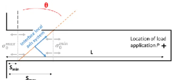
load-displacement curve of the nanoindenter, L the distance between the point of load application and the beam basis, S the distance between the beam basis and the fracture plane (
F
IGURE3
), z the height between the surface of the specimen and its center of gravity and IG its moment ofinertia (detailed in [14]).
For tilted interfaces, there are two possible values of S: Smax and Smin,
depending on the position of the interface for which the measurement is made. The two associated limiting values of stress 𝜎0𝑚𝑎𝑥 and𝜎0𝑚𝑖𝑛 frame
the apparent tensile stress σ0 at the interface in which the fracture
occurred (
F
IGURE3
).Figure 3 : Schematic of a specimen top surface, with the corresponding dimensions.
© (2020) R. Henry et al. (10.6084/m9.figshare.11999985) CC BY 4.0 license https://creativecommons.org/licenses/by/4.0/.
The apparent fracture stress σ0 can be decomposed into two components
in the interface local axis system (
F
IGURE3
): a tensile component σ and a shear component τ, linked by the interface angle θ [15] (cf. equations (2)). Using the bounds 𝜎0𝑚𝑖𝑛 and 𝜎0𝑚𝑎𝑥, stress components can also be bounded
by (𝜎𝑚𝑖𝑛 ,𝜎𝑚𝑎𝑥) and (𝜏𝑚𝑖𝑛, 𝜏𝑚𝑎𝑥).
𝜎 = 𝜎0. 𝑐𝑜𝑠2𝜃
𝜏 = 𝜎0. 𝑠𝑖𝑛 𝜃 . cos 𝜃
(2)
Given the expressions of σ and τ (equations (2)) and θ being comprised between 0° and 90°, σ is maximum for θ = 0°, null for θ = 90°, while τ is null for θ = 0° and θ = 90° and reaches a maximum value equal to σ when θ = 45°. Only above an angle of 45°, the shear component exceeds the opening stress component. For θ = 90°, interfaces are perpendicular to the cantilever axis and do not cross the cantilever width. These short interfaces (along platelet height) are only subjected to opening stress (no shear stress). Finally, in this case, the stress is mainly carried by the platelets.
3. Results and discussions
Eight specimens were prepared, each cantilever has been successfully tested and broke at an interface for angle θ up to 56°, which proved that the interface is weaker than platelets. For the specimen with 90° interfaces, the fracture had crossed platelets with some deviation along interfaces. Fracture stresses σ0 were calculated for every specimen using
equations (1) based on the fracture load and dimensions of each cantilever (
T
ABLE1
).Table 1 : Fracture loads, dimensions and resulting apparent fracture stress of every tested specimens.
n° θ (°) Pmax (mN) W (µm) B (µm) Smin (µm) Smax (µm) L (µm) σ0MAX (GPa) σ0MIN (GPa) 1 0 0.26 2.46 3.65 1.87 1.87 20.19 0.62 0.62 2 0 0.20 3.11 3.30 2.06 2.06 18.82 0.40 0.40 3 10 0.19 2.75 2.02 1.45 1.84 17.27 0.83 0.81 4 12 1.07 4.08 4.18 4.83 5.71 18.91 0.91 0.85 5 26 0.98 3.44 4.12 0.00 2.68 17.13 1.30 1.09 6 45 1.06 3.86 3.22 1.66 4.77 20.77 1.73 1.45 7 56 1.52 4.53 3.46 0.00 4.48 27.36 2.25 1.88 8 90 2.99 4.34 4.65 1.44 4.98 22.34 3.20 2.66
The σ and τ components were calculated from the apparent stress σ0 using
equations (2). Fracture stresses are plotted as a function of the interface angle θ (
F
IGURE4
). Each point represents the average value between the calculated bounds, i.e. the minimum and the maximum value of σ0, σ andτ, while error bars represent these minima and maxima. For the test with
interfaces perpendicular to the beam axis (θ = 90°), results cannot be directly compared to other values of θ: interfaces are solicited differently during the bending test, and the resulting strength is the one of a pack of aligned platelets.
Figure 4 : Apparent fracture (σ0), opening(σ) and shear (τ) stresses as a
function of the tested interface angle θ.
© (2020) R. Henry et al. (10.6084/m9.figshare.11999985) CC BY 4.0 license https://creativecommons.org/licenses/by/4.0/.
The apparent fracture stress σ0 increases quasi-linearly with the interface
angle θ, from about 500 MPa at 0° to 2 GPa at 56°. For θ = 90°, the apparent stress is much higher than other results, with an average value of 2.93 GPa (
F
IGURE2
). The shear stress τ also increases linearly with θ, is null for a perpendicular interface and reaches 1 GPa when θ reaches 56°. On the other hand, the local opening stress of the interface σ does not evolve linearly with θ. It seems to be bounded and is between 500 MPa for θ = 0°, reaches a maximum of almost 1 GPa for θ = 26°, then decreases to 600 MPa at θ = 56°. This apparent evolution of the opening stresses could be due to the scattering of measurements. In such experiments, the 𝜎0=𝑃𝑐. (𝐿 − 𝑆). 𝑧𝐼𝐺
error induced by the test (mainly related to the measurements of the specimen dimensions) is of the order of 10% of the measured stress value [16], and thus does not explain entirely the observed variation of versus θ (from 500 MPa to 1 GPa).
Every fracture surface was observed by SEM with a sample tilt angle of 54° (
F
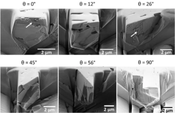
IGURE5
). Some fracture surfaces revealed porosities (θ = 12°), others showed steps corresponding to the local removal of a platelet (θ = 45°). However, all fracture surfaces showed smooth areas corresponding to flat interface zones (θ = 56°). In some spots, there is a certain roughness which probably corresponds to the glassy phase (θ = 26°), which does not seem to be homogeneous on fracture surfaces. In the θ = 90° case, the fracture crossed platelets. The resulting fracture surface shows that there are approximately ten platelets broken, and the crack had partly been deviated along an interface in the beam direction.Figure 5 : SEM images (54° of sample tilt) of the micro-cantilevers fracture surfaces, for interface angles θ from 0° to 90°. White arrows show the roughness present on some fracture surfaces.
© (2020) R. Henry et al. (10.6084/m9.figshare.11999985) CC BY 4.0 license https://creativecommons.org/licenses/by/4.0/.
EDS analysis were performed on fracture surfaces with an accelerating voltage of 10 kV (X-max SDD 80 mm², Oxford Instruments, Abingdon-on-Thames, United-Kingdoms) using a tilt of 54° (
F
IGURE6
). Some traces of gallium can be found on the micro-cantilevers edges, due to the FIB milling. However, the top surface, in traction during the test and where the fracture initiates, is not affected by gallium implantation as the surface is not milled. This suggests that the FIB milling process should not influence significantly the measured fracture properties. EDS maps also showed the presence of silicon which is attributable to silica contained in the glass-phase. This silica-rich phase does not appear homogeneous over the entire fracture surfaces and corresponds to the rough areas detected by SEM (θ = 26°) (F
IGURE6
). Also, on a smooth fracture surface, the EDS map shows almost no silica-rich zones (θ = 45°), the only small area present being on a triple grain boundary. This inhomogeneity in morphology, quantity of glassy phase and porosities at the interface probably contributes to the scattering of the stress values reported inF
IGURE4
.Figure 6 : SEM images and associated EDS maps of silicon of different micro-cantilever fracture surfaces. Silicon-rich areas (in light blue) visible on EDS maps correspond to interfaces and/or rough areas visible with SEM. White arrows show the roughness observed by SEM.
© (2020) R. Henry et al. (10.6084/m9.figshare.11999985) CC BY 4.0 license https://creativecommons.org/licenses/by/4.0/.
Finally, considering the scattering of the tensile stress values σ reached on the interface at failure, we can assume that σ is constant with θ (
F
IGURE4
). On the other hand, σ0 and τ evolve linearly with θ up to 56°.Thus it seems that neither the apparent stress σ0 nor the shear stress τ
drive the fracture here. In conclusion, the fracture seems to be driven by the opening stress σ locally undergone by the interface and is triggered for an average stress of 0.72 ± 0.18 GPa. Under the assumption that failure is driven by the interface opening stress, we can deduce that the shear strength is larger or equal to 1 GPa, which corresponds to the maximum value of reached for θ = 56°. The opening fracture stresses of interfaces (measured with θ up to 56°) are significantly lower than specimen with vertical interfaces (θ = 90°) or than values obtained with other mechanical tests performed on individual alumina platelets [12]. This shows that interfaces can withstand local stress levels about seven times lower than alumina platelets (5.3 ± 1.3 GPa in [12]), and about four times lower than a pack of aligned platelets (θ = 90°).
In order to link micromechanics data with observed macroscopic fracture behavior, fracture analysis of several notched bending specimens (SENB) with macroscopic dimensions were performed on 24 specimens with 5 different sizes [11]. The dimensions of the tested specimens varied from 2x5x30 mm3 up to 5x10x60 mm3, while the notch depth is always close to
a ratio of 0.4 times the specimen width. After testing, there is systematically a crack deviation observed, but also the crack is initiated on one edge of the notch, around 75 ± 4° relatively to the notch axis (
F
IGURE1
-
A). In isotropic materials, the crack is expected to initiate at the notch tip and propagate in the specimen middle plane. The specimens under investigation contain platelets oriented perpendicularly to the initial notch direction. Crack initiation and propagation along the notch direction would require to break platelets, which is not the most favorable damage mechanism. Indeed, it appears that a crack is more likely to be deviated at the interface than to penetrate through the platelets. This mechanism has been known for a long time in composite materials and is referred to as the Cook-Gordon effect [17].We performed a finite element modeling (FEM) of every macroscopic bending test using the specimen dimensions and notch radius (34.5 ± 7.0 µm, measured with an optical microscope). A 2D plane strain finite element model of the four-points bending test using Cast3m software (CEA, Paris, France) was set up. Linear elastic transversely isotropic behavior is adopted, with a Young’s modulus Ex = 320 GPa in the
direction of the platelet length, Ey = 368 GPa in the platelet height and a
Poisson’s ratio ν = 0.24 [11]. The shear modulus in the studied plane is taken as G = Ey / (2 (1 + ν)), i.e. equal to 131 GPa. Because of the test
symmetry, only one half of the specimen was modeled. The mesh is composed of quadrilateral quadratic elements, and is refined around the notch.
Stress fields are displayed in the area surrounding the notch root, for a load level corresponding to the measured fracture initiation load (
F
IGURE7
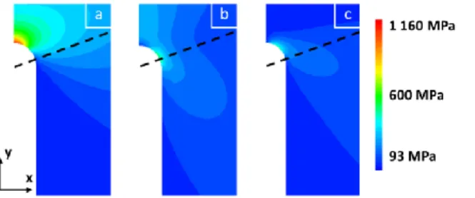
). The opening stress σxx is maximum at the notch tip, asexpected, and reaches 1.19 ± 0.13 GPa (
F
IGURE7
-
A)
. At these failure loads (measured experimentally), the loading levels are not sufficient to trigger the platelet failure. There are also secondary maximums of stress, opening stress σyy (0.45 ± 0.05 GPa) (F
IGURE7
-
B)
, and shear stress τxy(0.43 ± 0.05 GPa) that are not located at the notch tip but at the transition between the rounded and the straight notch sides (
F
IGURE7
-
C)
. The direction of the crack at initiation is reported by black dashed lines (as observed under an optical microscope after failure of the specimen (F
IGURE1
-
A)). The maximum stress σyy seems to correspond to theexperimental site of crack initiation. However, this FEM analysis also shows a local maximum shear stress that could be involved in the crack initiation.
Figure 7 : Example of contour maps of stress values calculated by FEM around the notch tip: (a) σxx, (b) σyy, (c) τxy. The dotted line represents the
crack direction, observed on Figure 1 - a.
© (2020) R. Henry et al. (10.6084/m9.figshare.11999985) CC BY 4.0 license https://creativecommons.org/licenses/by/4.0/.
The σxx/σyy stress ratio calculated for maximum values calculated by FEM
(respectively at the notch tip and at the crack initiation site on the notch side) is of 2.34 ± 0.05. According to micromechanics data obtained from micro-cantilever tests (
F
IGURE4
), the ratio of stress reached at failure is around 4 between an interface and a platelet pack, and around 7 between an interface and a single platelet. Thus, it appears that on macroscopic tests, the critical local opening stress of interfaces is reached on the notch side before the critical stress of platelets at the notch tip, even if platelets undergo a stress 2.34 times higher than interfaces. At the crack initiation site, the ratio of τxy/σyy calculated by FEM is around 0.3. According tomicromechanical tests, even when the shear stress is equal or exceeds the opening stress (θ = 45° and θ = 56° in
F
IGURE4
), it seems that the opening stress triggers the fracture. Thus, on macroscopic notched specimens of nacre-like alumina, it would appear that shear has little or no role in initiating the failure. The maximum stress value for σyy calculated by FEMon macroscopic specimens (0.45 ± 0.05 GPa) is compatible with the opening stress measured by micromechanics (0.72 ± 0.18 GPa). However, these two values are not straightforward to compare because between the two tested scales, both available mechanical energies [18] and defect distribution [19] are different.
4. Conclusions
In summary, the strength of interfaces between platelets of a nacre-like alumina has been evaluated by bending tests applied to micro-cantilevers milled by FIB. On the tested specimens, the larger the interface angle, the higher the apparent fracture stress. Calculations of stresses in the interface local axis system leads to the conclusion that the fracture seems to be driven by the opening stress undergone by the interface. Given the scattering of measurement, the critical value of opening stress is 0.72 ± 0.18 GPa, while the shear stress does not seem to act on the fracture for values up to 1 GPa. The analysis of crack initiation on macroscopic tests are consistent with these results: the crack initiates at a local maximum opening stress applied on interfaces of the material. These results are valuable for future modeling of fracture in this type of material. The apparent opening stress of individual interfaces is about seven times lower than the stress locally reached in platelets at failure [12], whereas numerical modelling of this material has shown that the optimum strength should be reached for a ratio of about 2.5 [20]. Therefore, it seems that there is still a margin of improvement in the fracture properties of this nacre-like alumina, for example by enhancing the strength of the interfaces.
Acknowledgements
The Agence Nationale pour la Recherche (ANR -16-CE08-0006 BICUIT, program DS0303-2016) is greatly acknowledged for its financial support. The CLYM (www.clym.fr) is also thanked for access to microscopes.
References
[1] M. A. Meyers, P. Y. Chen, A. Y. M. Lin, and Y. Seki, “Biological materials: Structure and mechanical properties,” Prog. Mater.
Sci., vol. 53, no. 1, pp. 1–206, 2008.
[2] F. Barthelat, H. Tang, P. D. Zavattieri, C. M. Li, and H. D. Espinosa, “On the mechanics of mother-of-pearl: A key feature in the material hierarchical structure,” J. Mech. Phys. Solids, vol. 55, no. 2, pp. 306–337, 2007.
[3] H. L. Gao et al., “Mass production of bulk artificial nacre with excellent mechanical properties,” Nat. Commun., vol. 8, no. 1, 2017.
[4] P. Pelissari et al., “Nacre-like ceramic refractories for high temperature applications,” J. Eur. Ceram. Soc., vol. 38, no. 4, pp. 2186–2193, 2018.
[5] F. Bouville, E. Maire, S. Meille, B. Van De Moortèle, A. J. Stevenson, and S. Deville, “Strong, tough and stiff bioinspired ceramics from brittle constituents,” Nat. Mater., vol. 13, no. 5, pp. 508–514, 2014.
[6] A. R. Studart, “Turning brittleness into toughness,” Nat.
Mater., vol. 13, no. 5, pp. 433–435, 2014.
[7] F. Bouville, “Strong and tough nacre-like aluminas: Process– structure–performance relationships and position within the nacre-inspired composite landscape,” J. Mater. Res., pp. 1–19, 2020.
[8] F. Bouville, E. Maire, and S. Deville, “Self-assembly of faceted particles triggered by a moving ice front,” Langmuir, vol. 30, no. 29, pp. 8656–8663, 2014, doi: 10.1021/la404426d. [9] H. Le Ferrand, F. Bouville, T. P. Niebel, and A. R. Studart,
“Magnetically assisted slip casting of bioinspired heterogeneous composites,” Nat. Mater., vol. 14, no. 11, pp. 1172–1179, 2015.
[10] K. Evers, S. Falco, N. Grobert, and R. I. Todd, “Nacre-like alumina with unique high strain rate capabilities,” J. Eur.
Ceram. Soc., vol. 40, no. 2, pp. 417–426, 2020.
[11] H. Saad et al., “A simple approach to bulk bioinspired tough ceramics,” preprint, 2020, https://hal.archives-ouvertes.fr/hal-02493649v1.
[12] E. Feilden et al., “Micromechanical strength of individual Al2O3
platelets,” Scr. Mater., vol. 131, pp. 55–58, 2017.
[13] D. Di Maio and S. G. Roberts, “Measuring fracture toughness of coatings using focused-ion-beam-machined microbeams,” J.
Mater. Res., vol. 20, no. 02, pp. 299–302, 2005.
[14] R. Henry et al., “Local fracture toughness measurements in polycrystalline cubic zirconia using micro-cantilever bending tests,” Mech. Mater., vol. 136, 2019.
[15] A. Doitrand and D. Leguillon, “Comparison between 2D and 3D applications of the coupled criterion to crack initiation prediction in scarf adhesive joints,” Int. J. Adhes. Adhes., vol. 85, no. May, pp. 69–76, 2018.
[16] W. Luo, C. Kirchlechner, X. Fang, S. Brinckmann, G. Dehm, and F. Stein, “Influence of composition and crystal structure on the fracture toughness of NbCo2 Laves phase studied by micro-cantilever bending tests,” Mater. Des., vol. 145, pp. 116–121, 2018.
[17] J. Cook, J. E. Gordon, C. C. Evans, and D. M. Marsh, “A mechanism for the control of crack propagation in all-brittle systems,” Proc. R. Soc. London. Ser. A. Math. Phys. Sci., vol. 282, no. 1391, pp. 508–520, 1964.
[18] D. Leguillon, “Strength or toughness ? A criterion for crack onset at a notch,” vol. 21, pp. 61–72, 2002.
[19] S. Johansson, J. Å. Schweitz, L. Tenerz, and J. Tirén, “Fracture testing of silicon microelements in situ in a scanning electron microscope,” J. Appl. Phys., vol. 63, no. 10, pp. 4799–4803, 1988.
[20] K. Radi, D. Jauffrès, S. Deville, and C. L. Martin, “Elasticity and fracture of brick and mortar materials using discrete element simulations,” J. Mech. Phys. Solids, vol. 126, pp. 101–116, 2019.
Keywords
Micro-cantilever bending test; Focused ion beam; Nacre-like alumina; Interface testing.