HAL Id: hal-01688048
https://hal.archives-ouvertes.fr/hal-01688048
Submitted on 19 Jan 2018
HAL is a multi-disciplinary open access
archive for the deposit and dissemination of
sci-entific research documents, whether they are
pub-lished or not. The documents may come from
teaching and research institutions in France or
abroad, or from public or private research centers.
L’archive ouverte pluridisciplinaire HAL, est
destinée au dépôt et à la diffusion de documents
scientifiques de niveau recherche, publiés ou non,
émanant des établissements d’enseignement et de
recherche français ou étrangers, des laboratoires
publics ou privés.
Partial discharge testing in aeronautic environment on
magnet wire and feeder cables
Thibaut Billard, Cédric Abadie, Thierry Lebey
To cite this version:
Thibaut Billard, Cédric Abadie, Thierry Lebey. Partial discharge testing in aeronautic environment
on magnet wire and feeder cables. EIC 2016 (Electrical Insulation Conference), Jun 2016, Montréal,
Canada. pp. 101-104. �hal-01688048�
O
pen
A
rchive
T
OULOUSE
A
rchive
O
uverte (
OATAO
)
OATAO is an open access repository that collects the work of Toulouse researchers and
makes it freely available over the web where possible.
This is an author-deposited version published in :
http://oatao.univ-toulouse.fr/
Eprints ID : 18193
To link to this article :
DOI: 10.1109/EIC.2016.7548577
URL :
http://dx.doi.org/10.1109/EIC.2016.7548577
To cite this version :
Billard, Thibaut and Abadie, Cédric and Lebey, Thierry
Partial discharge testing in aeronautic environment on magnet wire and feeder
cables. (2016) In: EIC 2016 (Electrical Insulation Conference), 19 June 2016 -
22 June 2016 (Montréal, Canada).
Any correspondence concerning this service should be sent to the repository
administrator:
[email protected]
Partial discharge testing in aeronautic environment on
magnet wire and feeder cables
Thibaut Billard
1and Cédric Abadie
1,21IRT Antoine de Saint Exupéry
118 Route de Narbonne, 31432 Toulouse, France [email protected]
Thierry Lebey
22Laboratoire Laplace, CNRS-UPS-INP line 2-name of 118
Route de Narbonne, 31062 Toulouse, France [email protected]
Abstract— Rationalization of energy sources aboard aircraft and improvements in more electric technologies are pushing the aeronautic industry to meet the all-electric aircraft challenge. As a result, onboard power has been steadily increasing, reaching 1MW for B787. AC and HVDC network voltage have followed reaching 230VAC and 540VDC increasing the likeliness of partial discharge. In the future, this shift will lead to the complete redesign of the architecture of onboard power systems. The aim of this study is to characterize the partial discharge inception voltage, with the aforementioned constraints in mind, on two components of the electromechanical chain: magnet wires used in electric actuators and feeder cable used in harness.
Keywords—Partial discharge; aeronautic; altitude; non-intrusive sensors; magnet wire; feeder cable.
I. INTRODUCTION
The paradigm shift towards more electrical aircraft architectures, such as B787, F-35 or A350, results in a higher risk of electrical discharges events such as gaseous breakdown, electrical arc and partial discharges. The latter phenomena being an important cause of concerns for component manufacturers as well as aircraft integrator because environmental, electrical stresses and cycling are, associated with mass reduction, all pointing in the direction of a higher likeliness of partial discharges events.
Obviously, when starting from atmospheric pressure, an altitude of 40,000 feet will decrease the partial discharge inception voltage according to Paschen's law and Townsend's theory for most aircrafts flying in the atmosphere. Even if most equipment are either already sealed or not in depressurized area, it may be not necessary the case for some actuators in commercial aircrafts or in more demanding military applications such as fighters or Unmanned Air Vehicles (UAV).
But main causes of this higher partial discharges risk are the increase of the network voltage (540 VDC and 230VAC) and power density among electromechanical chain. As a result, insulation system which are currently featuring large design margins have to be carefully analyzed and rationalized because operating voltage is now high enough to initiate partial discharges during operating conditions. The forthcoming use of wide band gap switches for inverter drive such as silicon carbide (SiC) or gallium nitride (GaN) will even more stress the insulation system, especially turn insulation of high speed
electric motor which have already very large and massive end-windings. Energy rationalization among aircraft has already resulted in the use of mutualized inverter than can drive several components in different flight situations. As a result, long harness (or feeder cables) will have to be used in order to connect the load to the power supply. The combination of short rise time and long cable ultimately leading either to overvoltage at motor terminals. [1-6]
In this paper, comparative measurements on typical electric motor magnet wires of different grade are made at various pressure using twisted pair of enamel wire. Feeder cable insulation is also studied using DC voltage at low pressure on a specifically designed tool to model a typical aircraft situation.
II. EXPERIMENTAL SET-UP
A. AC and DC power supply
A positive 5kV DC and 6kV AC RMS power supply is used to perform partial discharge inception level tests (PDIV). An input filter is embedded in the power supply along with a transformer to ensure that electric network noise is kept to a minimum while performing measurement. Voltage level are monitored using a Testec TT-SI 9010A (1/1000 ratio) active differential probe whose bandwidth is 70MHz.
B. Inductive and capacituve non-intrusive sensor
Technological research at IRT Saint-Exupéry are focused on non-intrusive sensors. These sensors and associated method have already prove to be effective for detecting partial discharge on-line on both electric motor in automotive [7] and aeronautic test benches [8].
The first non-intrusive sensor used to detect partial discharge is taking advantage of the capacitive effect. In other words, partial discharge small current impulses are transduced into voltage variations through the capacitance between the copper wire and ground. In order to increase signal amplitude, the capacitive effect could be enlarged using metallic adhesive, expanding capacitive surface, directly on the ground cable and making in effect a cylindrical electrode. Then, the jack-SMA sensor is put in contact with the metallic adhesive to gather analog variations of partial discharge signals. The sensor holds thanks to a 3D-printed clamp designed to be suitable with most aircraft feeder cable (up to 000 AWG). Electrical continuity is
then checked to be sure that the sensor is well connected to the cylindrical electrode.
The second non-intrusive sensors is a wideband fast current transformer (FCT) Bergoz FCT-016-1.25. The magnetic core is made of cobalt-based amorphous and nanocrystalline alloys which provide high permeability and very fast rise time. Low cut-off frequency (-3dB) is 9.5kHz and upper cut-off frequency (-3dB) is 1.75GHz. Since this FCT is better known than the capacitive sensor on the basis of previous experiments, the former will be used as a reference.
C. Analog high pass-filtering and wide band amplifier
When performing on-line measurement using non-intrusive sensor, it is usual to connect high-pass analog filter to remove electro-magnetical noise coming from inverter drive switches. Since only DC and AC voltage waveforms are tested here, no high-pass filter will be used for this purpose.
To increase signal to noise ratio, a coaxial low noise wide band (ZFL-1000LN+) amplifier has been used on the capacitive non-intrusive sensor alongside a coaxial high-pass filter (BHP-25+) whose cut-off frequency is 25MHz.
D. Analog to digital conversion and test methods
Analog to digital conversion is carried out using a four channels Keysight DSOS204A oscilloscope with a sampling rate of 20GSa/s and numerical bandwidth of 2GHz. When using AC voltage, the acquisition characteristics are 5MSa/s (200ns between points) with a file memory of 500k points for a total length of 100ms. Thus, at 50Hz, five voltage cycle are displayed on the oscilloscope screen to perform partial discharge inception level.
Vertical acquisition is in high resolution mode (13bits). With all electric equipments turned on and 100V RMS applied on the test set-up (with a sample), capacitive sensor noise level is 480!V while FCT sensor noise level is 80!V measured at 10ms/div.
When performing AC detection, real-time mode is used while with DC voltage detection, the roll mode acquisition is chosen alongside peak detect trigger option with a 2s/div.
E. Magnet wires and feeder cables samples
For this experiment, typical electrical motor copper magnet wires used in high-speed machines have been selected. All magnet wires are provided by the same manufacturer and are all with the basecoat made from THEIC – polyester_imide and a polyamide-imide overcoat. Nominal wire diameter is 0.71mm (AWG 21) which is standard in electrical motor applications and grade 1, grade 2 and grade 3 have been compared.
TABLE I. 0.71 MM MAGNET WIRE DETAILS
Grade 1 Grade 2 Grade 3 28!m 53!m 80!m
The twisted pair samples (five for each magnet wire type) are made according to EIC 60851 standard [3] and were not varnished nor impregnated. While performing measurements, a
small mechanical tension was applied to both end of the twisted pair to kept geometric variations to a minimum between sample during tests.
The feeder cable tested here is general purpose aircraft wire (AWG 8) made of nickel plated copper for its core (Stranded Conductor - 127 x 0.30mm) and rated for 600V according to EN 2267-010 standard. Its insulation is made of a layer of polyimide tape and layers of UV PTFE tape.
F. Testing equipments
In order to model a feeder cable in contact with a metal plate, a specific tool has been designed. Obviously in our lab experiment the metal plate is not protected with aeronautic surface treatment and is grounded while the feeder cable is energized with DC voltage. One should keep in mind that metal parts in aircraft may have different surface properties as well as different partial discharge related material properties such as secondary emission coefficient. Another thing is that the greater use of composite in aircraft structure may change the electric potential distribution in the vicinity of the cable.
All the tests have been carried out within a grounded vacuum chamber, acting as a faraday chamber, connected to a vacuum pump. This allows partial discharge tests and signal analysis at atmospheric and low pressures. The pressure is manually regulated using a manometer and a screw vacuum controller. The system is currently able to pressure from atmospheric to 20mbars with an accuracy of +/- 5 mbars. Partial discharge inception levels of the test set-up without samples have been checked before measurements (both at atmospheric and low pressure) and are significantly higher than those measured with samples.
III. MAGNET WIRE RESULTS
A. Partial discharge inception voltage
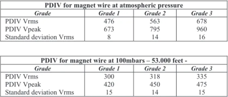
Partial discharge inception level voltage are measured in Volt RMS and converted in Volt peak. Ten measurements have been made on five twisted pair samples for each grade, thus fifty PDIV measures for each grade. The average of all these measurements and standard deviation are reported in table II. Altitude have been chosen at 100mbars (or 53.000 feet) high which is an upper limit since most long haul commercial airplanes are cruising at 190mbars (or 40.000 feet)
TABLE II. PARTIAL DISCHARGE INCEPTION VOLTAGE ON TWISTED PAUR OF MAGNET WIRE
PDIV for magnet wire at atmospheric pressure
Grade Grade 1 Grade 2 Grade 3
PDIV Vrms PDIV Vpeak Standard deviation Vrms 476 673 8 563 795 14 678 960 16
PDIV for magnet wire at 100mbars – 53.000 feet -
Grade Grade 1 Grade 2 Grade 3
PDIV Vrms PDIV Vpeak Standard deviation Vrms 300 420 15 318 450 14 335 475 15
On twisted pairs, PDIV results are typical of 0.71mm magnet wire with about 500Vrms for grade 1. For each upper grade, an increase of approximately 100Vrms for each level (26!m and 52!m) could be observed. At low pressure though, difference of PDIV between seems to be less significant with a lower limit of 300Vrms and an upper limit of around 340Vrms for grade 3. The low standard deviation indicator confirm that PDIV results are repetitive under atmospheric and low pressure environment for each grade. With a DC bus voltage of 540V, wide gap SiC or GaN and long harness, PDIV is almost sure to be reached in the worst case scenario which is simulated by twisted pair.
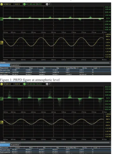
B. Amplitude analysis
Some difference between partial discharge at atmospheric and low pressure could be noticed on a Phase Resolved Partial Discharge (PRPD) display. PRPD plot at the same time phase of partial discharge and its amplitude in pC, correlated to a proper calibration. Since there is no widely accepted calibration method for non-intrusive sensor, only relative amplitude in mV will be compared. PRPD figures are made with 50 acquisitions at PDIV level for 0.71mm wire – grade 2 with the FCT sensor.
The main result here is the fact that amplitude at PDIV level at low pressure is several times higher than the amplitude at atmospheric pressure in figure 1 and figure 2.
Figure 1: PRPD figure at atmospheric level
Figure 2: PRPD figure at 100mbars
Figure 3: Zoom on typical partial discharge at atmospheric pressure
Figure 4: Zoom on typical partial discharge at low pressure
C. Partial discharge shape
When observing closely (1.25 GSa/s and 800ps/point) partial discharge signals (fig. 3 and fig. 4.) it could be noticed that the frequency content is not same at different pressure. This, alongside with the amplitude difference has already been reported by electrically connected sensors in air with twisted electrodes [9]. Non-intrusive sensors (both FCT and capacitive) are also sensitive to this effect.
IV. FEEDER RESULTS
Partial discharge inception level voltage under DC voltage are measured in Volt peak. To simulate a “turn-on” on an electrical network, DC voltage has been applied like an impulse and PDIV was determined on the recurrence of discharge event (at least 1 event per minute) with a voltage increase of 100V for each step. The cable place in parallel contact with a 5cm wide metallic plate to simulate ground as shown in figure 5 above. Observed PDIV was 4kV DC at atmospheric pressure and 3.1kV at low pressure.
Figure 6: Typical DC discharge behavior 500V above PDIV
Figure 7: Zoom on partial discharge signal at low pressure (bottom) and atmospheric pressure (top)
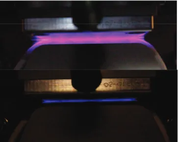
Figure 8: Picture of partial discharge at low pressure (top) and atmospheric pressure (bottom) with (30s accumulation at PDIV level)
Figure 6 show the typical behavior of DC positive discharge with a regular time constant between events which is related to materials characteristics. Contrary to AC signals, it seems that partial discharge spectra under DC voltage is not evolving with pressure as shown in figure 7. Pictures of partial discharge on the feeder-plane and allows observations of
events occurring in air. Partial discharge in air at low pressure and at PDIV level are much more large in volume than those occurring on the same test equipment but at low pressure (fig. 8)
DISCUSSION
Several key points could be summarized from this study. First, typical magnet wire used electric motors may not withstand an increase of voltage in the worst case scenario at low pressure even with brand new wires. Second, amplitude of partial discharge at low pressure is several times higher than the amplitude at atmospheric pressure. Further studies are required to investigate on degradation mechanisms at low pressure compared to atmospheric pressure. Third, since frequency spectrum of partial discharge is changing with pressure, de-noising and filtering techniques may have to be adapted to a low pressure environment when motors are fed with inverters drives. Finally, partial discharge under positive DC voltage does not seem to be sensitive to pressure variation regarding its frequency spectra or amplitude although PDIV is of course lower at 100mbars. Nature of discharge related to both environment (pressure) and voltage waveforms (no polarity reversal) may be at work to explain such a behavior [10].
Future investigations will look into the effect of pressure in magnet wire degradation and frequency spectrum under DC voltage
REFERENCES
[1] F. Koliatene, Impact of the aeronautic environment on the partial discharges ignition: A basic study, IEEE, 2008
[2] Christou, Methods for partial testing of aerospace cables, IEEE, 2009 [3] Brockschmidt, Electrical environments in aerospace applications, IEMD,
1999
[4] I. Cotton, A. Nelms, "Higher voltage aircraft power systems," in Aerospace and Electronic Systems Magazine, IEEE , vol.23, no.2, pp.25-32, Feb. 2008
[5] I. Moir, A. Seabridge “Aircraft Systems: Mechanical, Electrical and Avionics Subsystems Integration, 3rd Edition”, August 2011
[6] X. Roboam, "New trends and challenges of electrical networks embedded in “more electrical aircraft”," in Industrial Electronics (ISIE), 2011 IEEE International Symposium on , vol., no., pp.26-31, 27-30 June 2011
[7] T. Billard, T. Lebey, F. Fresnet, “Partial discharge in electric motor fed by a PWM inverter: off-line and on-line detection," in Dielectrics and Electrical Insulation, IEEE Transactions on , vol.21, no.3, pp.1235-1242, June 2014
[8] B. Cella, T. Lebey, C. Abadie,. "Partial discharges measurements at the constituents' level of aerospace power electronics converters", Electrical Insulation Conference (EIC), 2015 IEEE, On page(s): 274 – 277 [9] D. L. Schweickart, D. F. Grosjean, D. G. Kasten, S. A Sebo, X. Liu,
"Low-Pressure Partial-Discharge Measurements: Monitoring the Insulation Integrity of Aircraft Power Wiring Systems," in IEEE International Power Modulators and High Voltage Conference, Proceedings of the2008 , vol., no., pp.568-571, 27-31 May 2008 [10] T. Billard, T. Lebey, A. Belinger, N. Naude, N. Gherardi, "On the nature
of the discharges in samples fed by bipolar pulse like voltage and its possible impact on the detection of partial discharge in machines fed by inverter," in Electrical Insulating Materials (ISEIM), Proceedings of 2014 International Symposium on , vol., no., pp.200-203, 1-5 June 2014.