Design and construction of the MicroBooNE detector
The MIT Faculty has made this article openly available. Please share
how this access benefits you. Your story matters.
Citation
Acciarri, R., C. Adams, R. An, A. Aparicio, S. Aponte, J. Asaadi, M.
Auger, et al. “Design and Construction of the MicroBooNE Detector.”
Journal of Instrumentation 12, no. 02 (February 24, 2017): P02017–
P02017.
As Published
http://dx.doi.org/10.1088/1748-0221/12/02/P02017
Publisher
IOP Publishing
Version
Original manuscript
Citable link
http://hdl.handle.net/1721.1/121026
Terms of Use
Creative Commons Attribution-Noncommercial-Share Alike
Prepared for submission to JINST
Design and Construction of the MicroBooNE Detector
The MicroBooNE Collaboration
R. Acciarrig C. Adamsaa R. AnhA. Apariciog S. Aponteg J. AsaadixM. AugeraN. Ayoubf
L. BagbygB. BallergR. BargergG. BarrqM. BassqF. Bayy K. BierygM. BishaibA. Blakej
V. BoceangD. BoehnleingV. D. BogertgT. BoltoniL. BugelmC. Callahanf L. Camillerif
D. Caratellif B. CarlsgR. Castillo FernandezgF. CavannagS. Chappag H. Chenb K. Chenb
C - Y. Chif C. S. ChiumE. ChurchrD. Ciancil,fG. H. CollinmJ. M. ConradmM. Converyv
J. Corneleg P. Cowang J. I. Crespo-Anadónf G. CrutchergC. DarvegR. Davisg M. Del Tuttoq
D. Devittj S. Duffinb S. DytmansB. Eberlyv A. EreditatoaD. EricksongL. Escudero Sanchezc
J. EsquivelwS. FarooqiJ. FarrellbD. Featherstong B. T. Flemingaa W. Foremand
A. P. FurmanskilV. Gentyf M. Geynismang D. GoeldiaB. Goffp S. GollapinniiN. Grafs
E. GramelliniaaJ. Greeng A. GreenemH. GreenleegT. GriffingR. GrossoeR. Guenetteq
A. HackenburgaaR. HaenniaP. Hamiltonw P. HealeygO. HenmE. HendersonoJ. Hewesl
C. HilllK. Hillg L. HimesiJ. HodG. Horton-Smithi D. HuffmangC. M. IgnarramC. Jamesg
E. JamesgJ. Jan de VriescW. Jaskiernyg C.-M. JenzL. JiangsB. JohnsongM. Johnsong
R. A. JohnsoneB. J. P. JonesmJ. Joshib H. JostleingD. Kalekof L. N. Kalousisz
G. Karagiorgil,f T. KatorimP. KelloggpW. KetchumgJ. KilmergB. KinggB. KirbybM. Kirbyg
E. KleinaaT. Kobilarcikg I. KresloaR. KrullgR. KubinskigG. LangezF. LannibA. Lathropg
A. LaubeqW. M. Leeg,1Y. LibD. Lissauerb A. Listerj B. R. Littlejohnh S. LockwitzgD. Lorcaa
W. C. LouiskG. Lukhaning M. LuethiaB. Lundbergg X. LuoaaG. MahlerbI. Majorosp
D. Makowieckib A. Marchionnig C. MarianizD. MarkleygJ. MarshallcD. A. Martinez Caicedoh
K. T. McDonaldtD. McKeeiA. McLeanoJ. MeadbV. MeddageiT. MicelioG. B. Millsk
W. MinergJ. MoonmM. MooneybC. D. MooregZ. MossmJ. MousseaunR. Murrellsl
D. NaplessP. NienaberuB. Norrisg N. NortondJ. Nowakj M. O’BoylegT. Olszanowskig
O. PalamaragV. PaolonesV. PapavassiliouoS.F. PateoZ. PavlovicgR. Pelkeyz M. Phippsf
S. PordesgD. PorziolG. PulliamwX. QianbJ. L. Raafg V. RadekabA. RafiqueiR. A Rameikag
B. RebelgR. RechenmachergS. Resciab L. RochestervC. Rudolf von RohraA. Rugab
B. Russellaa R. SandersgW. R. Sands IIItM. SarychevgD. W. SchmitzdA. Schukraftg
R. Scottg W. Seligmanf M. H. Shaevitzf M. Shoung J. SinclairaW. Sippachf T. Smidtm
A. Smithf E. L. Sniderg M. SoderbergwM. Solano-GonzalezzS. Söldner-Remboldl
S. R. SoletiqJ. SonderickerbP. Spentzourisg J. SpitznJ. St. JohneT. Straussg K. Suttonf
A. M. SzelclK. TaherigN. Taggp K. Tatumf J. Tengg K. Teraof M. ThomsoncC. Thornb
J. TillmangM. ToupsgY.-T. TsaivS. Tufanliaa T. UshervM. Utesg R. G. Van de Waterk
C. Vendettag S. VerganimE. Voiring J. VoiringB. VirenbP. WatkinspM. WeberaT. Westerm
J. WestoncD. A. WickremasinghesS. WolbersgT. WongjiradmK. WoodruffoK. C. Wub
T. Yangg B. YubG. P. Zellerg J. ZennamodC. ZhangbM. Zuckerbrotg
aUniversität Bern, Bern CH-3012, Switzerland
bBrookhaven National Laboratory (BNL), Upton, NY, 11973, USA cUniversity of Cambridge, Cambridge CB3 0HE, United Kingdom dUniversity of Chicago, Chicago, IL, 60637, USA
eUniversity of Cincinnati, Cincinnati, OH, 45221, USA fColumbia University, New York, NY, 10027, USA
gFermi National Accelerator Laboratory (FNAL), Batavia, IL 60510, USA hIllinois Institute of Technology (IIT), Chicago, IL 60616, USA
iKansas State University (KSU), Manhattan, KS, 66506, USA jLancaster University, Lancaster LA1 4YW, United Kingdom
kLos Alamos National Laboratory (LANL), Los Alamos, NM, 87545, USA lThe University of Manchester, Manchester M13 9PL, United Kingdom mMassachusetts Institute of Technology (MIT), Cambridge, MA, 02139, USA
nUniversity of Michigan, Ann Arbor, MI, 48109, USA
oNew Mexico State University (NMSU), Las Cruces, NM, 88003, USA pOtterbein University, Westerville, OH, 43081, USA
qUniversity of Oxford, Oxford OX1 3RH, United Kingdom
rPacific Northwest National Laboratory (PNNL), Richland, WA, 99352, USA sUniversity of Pittsburgh, Pittsburgh, PA, 15260, USA
tPrinceton University, Princeton, NJ, 08544, USA
uSaint Mary’s University of Minnesota, Winona, MN, 55987, USA vSLAC National Accelerator Laboratory, Menlo Park, CA, 94025, USA wSyracuse University, Syracuse, NY, 13244, USA
xUniversity of Texas, Arlington, TX, 76019, USA
yTUBITAK Space Technologies Research Institute, METU Campus, TR-06800, Ankara, Turkey zCenter for Neutrino Physics, Virginia Tech, Blacksburg, VA, 24061, USA
aaYale University, New Haven, CT, 06520, USA
Abstract: This paper describes the design and construction of the MicroBooNE liquid argon time projection chamber and associated systems. MicroBooNE is the first phase of the Short Baseline Neutrino program, located at Fermilab, and will utilize the capabilities of liquid argon detectors to examine a rich assortment of physics topics. In this document details of design specifications, assembly procedures, and acceptance tests are reported. Keywords: Time projection chambers; Noble liquid detectors; Neutrino detectors
Contents
1 Introduction and Physics Motivation 2
2 Experiment Overview 4
2.1 The MicroBooNE LArTPC 4
2.2 MicroBooNE LArTPC Implementation 7
3 Cryogenic System 9
3.1 Cryostat Design Overview 9
3.2 Liquid Argon Purification Subsystem 13
3.3 Nitrogen Refrigeration 16
3.4 Controls and Purity Monitoring 16
3.5 Initial Purification 17
4 Liquid Argon Time Projection Chamber 19
4.1 Cathode 20
4.2 Field Cage 22
4.2.1 Resistor Divider Chain 23
4.3 Anode Planes 28
4.3.1 Mechanical structure 28
4.3.2 Wire winding and quality assurance 28
4.4 Parts Preparation 30
4.4.1 Cleaning stainless steel 30
4.4.2 Cleaning G-10 31
4.5 Assembly 31
4.5.1 Wire installation and tension measurements 32
4.6 High Voltage System 33
5 Light Collection System 36
5.1 Light Production in Argon 37
5.2 The Primary Light Collection System 39
5.2.1 Photomultiplier Tubes, Bases, and Initial Tests 40
5.2.2 Wavelength-Shifting Plates 42
5.2.3 UV Light Protection for the Wavelength-Shifting Plates 44
5.2.4 Cryogenic Mu Metal Shields 45
5.2.5 Implementation of the Primary System 46
5.3 PMT Testing and Quality Assurance 49
5.4 Secondary System: Acrylic Light Guides for R&D 49
5.5 Calibration 51
5.6 Coupling of PMT Signals to the Anode Wires 52
6 Electronics and Readout Systems 57
6.1 Cryogenic Low-Noise Electronics 57
6.1.1 CMOS ASIC 58
6.1.2 Cold Motherboards 58
6.1.3 Cold Cables 60
6.1.4 Electronic Calibration 60
6.1.5 Performance Tests 61
6.2 Warm Electronic Amplification 62
6.3 LArTPC Readout Electronics 64
6.3.1 Data Digitization 66
6.3.2 Data Handling 66
6.3.3 Compression Schemes 69
6.4 PMT Readout Electronics 70
6.4.1 PMT Signal Amplification and Shaping 71
6.4.2 PMT Data Digitization 71
6.4.3 PMT Data Handling and PMT Trigger Generation 72
6.5 Level-1 Trigger Generation 73
6.6 DAQ Design 75
6.7 High-Level Software Trigger 77
7 Infrastructure and Monitoring Systems 79
7.1 Electronics Infrastructure at LArTF 79
7.1.1 AC Power Distribution and Grounding for Low-Noise LArTF
Data-taking 79
7.1.2 DC Power Distribution to the MicroBooNE Detector 82
7.1.3 Network, Timing, and Data Distribution for Low-Noise LArTF
Data-taking 82
7.1.4 Interlocks and Safety Systems 85
7.1.5 Performance Measurements 85
7.2 Slow Monitoring and Control System 85
7.3 Beam Monitoring 87
8 UV Laser System 89
8.1 UV Laser Calibration 91
8.2 Laser Source and Optics 92
8.3 Steering System 94
8.4 Performance Tests and Initial Operation 94
1 Introduction and Physics Motivation
The Micro Booster Neutrino Experiment (MicroBooNE) employes a large (∼100 tonnes) Liquid Argon Time Projection Chamber (LArTPC) detector designed for precision neu-trino physics measurements. MicroBooNE is the latest among a family of detectors that exploit the potential of liquified noble gases as the detection medium for neutrino interac-tions. These detectors combine the advantages of high spatial resolution and calorimetry for excellent particle identification with the potential to scale to very large volumes.
Large calorimeters using cryogenic noble liquids combined with active components were recognized in the 1970s as having use for particle physics applications [1]. Specifically, much of the liquid argon based technology was developed within the ICARUS program [2–4] culminating in the realization of the ICARUS T600 detector [5]. On a much smaller scale than the ICARUS detector, the ArgoNeuT (Argon Neutrino Test) experiment operated a ∼0.25 tonne LArTPC from 2009-2010 in the NuMI neutrino beam at Fermilab. ArgoNeuT performed a series of detailed studies on the interaction of medium-energy neutrinos [6] producing the first published neutrino cross section measurements on argon [7–9]. Next generation LArTPCs for the Short Baseline Neutrino Detector (SBND) experiment and the Deep Underground Neutrino Experiment (DUNE) are now being designed and constructed. MicroBooNE ’s principal physics goal is to address short baseline neutrino oscillations, primarily the MiniBooNE observation of an excess of electron-like events at low energy [10], at the Fermi National Accelerator Laboratory (Fermilab). MicroBooNE will be exposed to the 0.5-2 GeV on-axis Booster Neutrino Beam (BNB) at a ∼500 m baseline, the same as was employed for MiniBoonE. The MicroBooNE experiment is exploiting the LArTPC technol-ogy because of its superior capability for separation of signal electrons from the background of photon conversions. While the mass of MicroBooNE is significantly less than the mass of MiniBooNE, this superior discrimination is expected to address the MiniBooNE result at the 5σ level.
In addition to MicroBooNE’s signature oscillation analyses, a suite of precision cross-section measurements will be performed, critical both for future LArTPC oscillation ex-periments and for understanding neutrino interactions in general. In the BNB, multiple interaction processes (quasi-elastic, resonances, deep inelastic scattering) are possible, and complicated nuclear effects in neutrino interactions on argon result in a variety of final states. These can range from the emission of several nucleons to more complex topologies with multiple pions, all in addition to the leading lepton in charged-current events. The LArTPC technology employed by MicroBooNE is particularly well suited for complicated topologies because of its excellent particle identification capability and calorimetric energy reconstruction down to very low detection thresholds. MicroBooNE’s physics program also encompasses searches for supernova and proton decay. The detector is capable of recording neutrinos from a galactic supernova which would result in ∼30 charged current neutrino interactions in MicroBooNE’s active volume. The detector will measure proton decay-like signatures and backgrounds and develop the analysis for this search; though its target mass is insufficiently large to enable a competitive sensitivity, the analysis will provide an important proof-of-principle for future searches in more massive detectors.
MicroBooNE began operations in late 2015 for an initial anticipated ∼3 year run. In 2018, MicroBooNE will continue operations as part of an expanded Short Baseline Neutrino (SBN) program [11] at Fermilab that includes continued operation of MicroBooNE (at 470 m) along with the SBND (at 110 m) and ICARUS (at 600 m) detectors. The SBND and ICARUS experimental halls and detectors are presently under construction. MicroBooNE will definitively address whether or not the MiniBooNE low energy excess in neutrino mode is due to electrons or photons in its initial run. SBND will look for this low energy excess at the near location and ICARUS, with its larger mass, will enable the three detector program to cover the entire LSND-allowed region in neutrino parameter space with 5σ sensitivity in the νe appearance channel.
This document describes the design, construction, and technical details of the Micro-BooNE detector. Section2gives a brief review of the LArTPC technique and its implemen-tation in MicroBooNE. Section3describes the cryogenic and purification systems which are required for maintaining a stable volume of highly purified liquid argon. The LArTPC de-scribed in section 4 is the centerpiece of the experiment, providing fine-grained images of neutrino interactions. A light collection system, described in section 5, provides timing information, used primarily for triggering beam events, from the prompt scintillation light that is produced in the detector volume. Signals from the light collection system and from the LArTPC are amplified, sampled, and recorded by a custom-designed electronic and readout system, as described in section6. Section7describes the auxiliary instrumentation that monitor and control the detector and all of its associated systems, as well as provide an electrically quiet environment for the experiment to operate. Finally, one of the main calibration sources for the experiment is an ultraviolet laser system, described in section8, that provides the capability to map out geometric track distortions, as induced, for exam-ple, by space charge. A cosmic ray tagger system, under construction at the time of the writing of this paper, will surround the detector to improve cosmic ray identification and rejection. This system will be described in a subsequent publication.
More information on the LArTPC technology can be found in existing reviews (see, e.g., [12] and references therein).
Figure 1. Aerial diagram showing location of MicroBooNE along the BNB (orange dashed line) at Fermilab.
2 Experiment Overview
The MicroBooNE detector at Fermilab in Batavia, Illinois is sited in the Liquid Argon Test Facility (LArTF) on axis in the BNB, 470 m downstream from the neutrino production target. The BNB delivers a beam of predominantly muon neutrinos produced primarily from pion decays, with energies peaking at 700 MeV [13]. MicroBooNE is also exposed to an off-axis component of the NuMI beam [14] produced from pion and kaon decays with average neutrino energies of about 0.25 GeV and 2 GeV respectively. MicroBooNE is located about 600 m downstream from the NuMI neutrino production target. The characteristics of the BNB beamline are well measured and understood from many years of data taking and analysis from the MiniBooNE experiment [13], which operated directly downstream of the MicroBooNE location. Figure1shows the arrangement of MicroBooNE with respect to the BNB beamline at Fermilab. The physics program of MicroBooNE will utilize both BNB and NuMI samples. MicroBooNE will also collect data that is out-of-time with either beam, which will be useful for developing non-accelerator neutrino-based analyses (e.g. proton decay and supernovae burst neutrino searches) relevant for next-generation detectors. 2.1 The MicroBooNE LArTPC
Charged particles traversing a volume of liquid argon leave trails of ionization electrons in their wake and also create prompt vacuum ultraviolet (VUV) scintillation photons. In a LArTPC, the liquid argon is highly purified so that the ionization trails can be transported with minimal attenuation over distances of the order of meters [15] under the influence of a uniform electric field in the detector volume, until they reach sense planes located along one side of the active volume. The electric field is created by introducing voltage onto a cathode plane and gradually stepping that voltage down in magnitude across a field cage, which is formed from a series of equipotential rings surrounding the drift volume. Non-uniformities in the electric field, diffusion, recombination, and space charge effects modify the tracks as they are transported. Calibration of these effects is critical to reconstruction of the initial ionization trails.
Cathode Plane
Edrift
U V Y
Liquid Argon TPC
Y wire plane waveforms
V wire plane waveforms Sense Wires
t Incoming Neutr
ino
Charged Particles
Figure 2. Operational principle of the MicroBooNE LArTPC.
The anode plane is arranged parallel to the cathode plane, and in MicroBooNE, parallel to the beam direction. There are three planes comprised of sense wires with a characteristic pitch, held at a predetermined bias voltage, that continuously sense the signals induced by the ionization electrons drifting towards them [16]. The electrostatic potentials of the sequence of anode planes allow ionization electrons to pass undisturbed by the first two planes before ultimately ending their trajectory on a wire in the last plane. The drifting ionization thus induces signals on the first planes (referred to as induction planes) and directly contributes to the signals in the final plane (referred to as the collection plane). Figure2depicts the arrangement of the MicroBooNE LArTPC and its operational principle. The charged particle trajectory is reconstructed using the known positions of the anode plane wires and the recorded drift time of the ionization. The drift time is the difference between the arrival times of ionization signals on the wires and the time the interaction took place in the detector (t0) which is provided by an accelerator clock synchronized to
the beam (BNB or NuMI) or from a trigger provided by the light collection system. The characteristics of the waveforms observed by each wire provide a measure of the energy deposition of the traversing particles near that wire, and, when taken as a whole for each contained particle’s trajectory, allow for determination of momentum and particle identity. The scintillation photons are detected by a light collection system that is immersed in
the liquid argon and faces into the detector volume. This system provides signals that can establish the event t0 and supplies trigger information to an electronic readout system. The
light collection system signals are vital in distinguishing detector activity that is in-time with the beam (and therefore possibly originating from beam interactions) from activity which is out-of-time (and therefore probably not associated with the beam), benefiting triggering and event reconstruction. Information on the z and y position of an interaction can also be inferred from the light system, further aiding in the reconstruction.
Liquid argon as a target for neutrinos is attractive due to its density, allowing a more compact detector with a substantial boost in event rate over a comparable detector using less dense media. A tradeoff to this aspect is the fact that the complicated structure of the argon nucleus (relative to hydrogen or helium, for example) will introduce nuclear effects that the data analysis must take into account. The cryogenic temperatures at which the noble elements are in the liquid phase also introduces the need for additional design considerations to ensure stable and safe operations.
Table 1lists some of the properties of liquid argon that are salient for LArTPC design. The noble liquids produce copious numbers of UV photons for every traversing charged particle, as well as large amounts of ionization. The electrons from this ionization can be drifted for distances of meters under a modest electric field (∼500 V/cm). Finally, building LArTPCs on increasingly large scales for neutrino detection becomes economically possible, given the abundance (1% of atmosphere) and low cost of argon and the convenient feature that it can be maintained as a liquid through refrigeration using liquid nitrogen which is plentiful and cheap.
Table 1. Selected properties of liquid argon.
Property Value Reference
Atomic number 18
Atomic weight [g/mol] 39.95
Boiling point [K] @ 1 atm 87.3 [17]
Density [g/cm3] @ 1 atm 1.394 [17]
Dielectric constant 1.505 [18]
Radiation length [cm] 14.0 [19]
Molière radius [cm] 10.0 [19]
W-value for ionization [eV/pair] 23.6 [20,21]
Minimum specific energy loss [MeV/cm] 2.12 [19]
Electron transverse diffusion coef. [cm2/s] 13 [3,22,23]
Electron longitudinal diffusion coef. [cm2/s] 5 [3,24]
The successful implementation of the LArTPC technique depends critically on a num-ber of factors. The liquid argon must be purified of any electronegative contaminants, such as water or oxygen, to accommodate the very long drift path of ionization through a MicroBooNE-sized LArTPC without significant charge loss. The signals that the ioniza-tion electrons create on the anode wires are very small, requiring low-noise electronics to discriminate between signal pulses and background noise. The MicroBooNE collaboration
has designed and constructed an experiment that addresses these considerations, provid-ing critical technological development upon which the next generation of LArTPCs may capitalize.
2.2 MicroBooNE LArTPC Implementation
MicroBooNE’s LArTPC active volume, which is defined as the volume immediately within the confines of the LArTPC field cage, is a rectangular liquid argon volume with dimensions as given in table 2. This is the maximum volume that can be used for physics analyses. The cathode and the anode planes define the beam-left and beam-right sides of the active volume. The end of the LArTPC that the beam first encounters is referred to as the “upstream” end, while the opposite end is referred to as “downstream.” Anode plane-to-plane spacing is 3 mm, and each plane-to-plane has 3 mm wire pitch. The induction plane-to-plane wires are oriented at ±60◦ relative to vertical, and the collection plane wires are oriented vertically.
Field cage loops are employed to maintain uniformity of the electric field across the entire width of the detector, and these loops also act to define the top, bottom, upstream, and downstream sides of the active volume.
MicroBooNE uses a right-handed Cartesian coordinate system, with the origin defined to be located on the upstream face of the LArTPC, centered halfway up the vertical height of the active volume and horizontally centered on the anode plane closest to the cathode (the innermost anode plane). In this system, x ranges from 0.0 m at the innermost anode plane to +2.6 m at the cathode, y ranges from −1.15 m on the bottom of the active volume to +1.15 m at the top of the active volume, and z ranges from 0.0 m at the upstream end of the active volume to +10.4 m at the downstream end.
The light collection system, an array of photomultiplier tubes (PMTs) and lightguide paddles, is located directly behind the anode planes on beam-right, facing the detector volume through the anode planes. The LArTPC and light collection system are immersed in liquid argon contained within a single-walled cryostat with a 170 tonne capacity. Analog front-end electronics mounted directly on the LArTPC amplify the signals on the wires; these signals are then passed out of the cryostat for further processing and storage on disk. Table 2 lists the primary detector design parameters of MicroBooNE, and figure 3 shows a schematic of the cross section of the detector. Details of these design parameters and construction of all detector systems will be provided in the subsequent sections.
Figure 3. Schematic of the cross section of the MicroBooNE LArTPC. In this view, the beam would be directed out of the page (in the z direction).
Table 2. Primary detector design parameters for MicroBooNE.
Parameter Value
LArTPC Dimensions 2.325 m vertically
2.560 m horizontally 10.368 m longitudinally
LArTPC argon mass 90 tonnes
Total Number of Wires 8256
Drift field 500 V/cm
Light collection 32 200 mm (8 in) diameter PMTs
4 lightguide paddles
Total liquid argon mass 170 tonnes
Operating temperature 87 K
3 Cryogenic System
The use of large quantities of highly-purified liquid argon as a detector medium in Micro-BooNE requires a sophisticated cryogenic infrastructure that can maintain stable operations for many years with minimal downtime. Not only must the purity of the liquid argon be maintained, but the pressure and temperature gradients within the LArTPC active volume must be tightly controlled as the drift velocity of electrons is dependent on these quanti-ties. A customized cryogenic system that serves these purposes has been built, and the requirements for this system are shown in table 3.
Table 3. Primary design requirements for MicroBooNE cryogenic and purification systems.
Parameter Value Motivation
Argon purity <100 ppt O2 equivalent MIP identification at longest drift
Argon purity <2 ppm N2 Scintillation light output
LAr temperature gradient <0.1 K throughout volume Drift-velocity uniformity
LAr recirculation rate 1 volume change/2.5 days Maintain purity
Cryostat heat load <15 W/m2 Minimize convection and bubbles
Cryogenic cooling capacity 10 kW Capacity for expected heat load
Cryostat max. operating pressure 2.1 bar Determines relief sizing
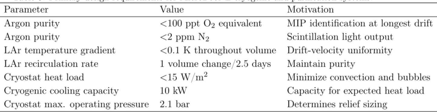
The MicroBooNE cryogenic system is represented in figure 4. The central component of the system is a cryostat that houses the complete LArTPC and light-collection detector systems. The cryostat is supported by three major subsystems: the argon purification system, the nitrogen refrigeration system, and the controls and monitoring system. These systems each represent the next generation of LArTPC cryogenic system after the Liquid Argon Purity Demonstrator (LAPD) [25] and make considerable use of the expertise gained during the design and implementation of that apparatus.
3.1 Cryostat Design Overview
Three major components make up the MicroBooNE cryostat: a type 304 stainless steel vessel to contain the liquid argon and all the active detector elements, front and rear supports to carry the weight of the fully loaded cryostat, and foam insulation covering the cryostat outer surfaces. The foam insulation serves to reduce heat input from the ambient environment to a sufficiently low level to prevent large temperature gradients and boiling of the liquid argon. The cryostat and the cryogenic systems are designed to achieve the requisite high purity of liquid argon needed to allow ionization electrons to drift to the anode wires with low probability of capture, and the high degree of thermal homogeneity needed to avoid introducing non-constant drift velocities for the ionization electrons. Finally, the outer diameter of the vessel is designed to be the maximum standard size for highway transport.
The cryostat is constructed to the American Society of Mechanical Engineers (ASME) boiler code requirements [26] and features a single-walled construction, cylindrical shape, and domed caps closing each end, as shown in figure 5. The cryostat is 12.2 m in overall
Figure 4. A rendering showing the MicroBooNE cryostat and cryogenic system, and the platform for the electronics racks as installed in LArTF.
length, with an inner diameter of 3.81 m, and a wall thickness of 11.1 mm. When empty the cryostat weighs ∼17,000 kg. One end was removed for installation of the active detectors, welded back in place upon completion of that task, and then re-certified to the ASME code requirements.
Ionization electrons must not be significantly attenuated, via attachment to electroneg-ative contaminants in the liquid argon while they drift up to 2.5 m across the active volume. This dictates that the argon be kept free of electronegative contaminants to the level of 100 parts-per-trillion (ppt) oxygen-equivalent (O2 equivalent), where the choice of O2
equiva-lent units implies other polar molecules besides oxygen may be present, but the attachment rate constant for oxygen is used in calculations . The cryostat is designed to minimize outgassing (desorption) and to avoid leakage and diffusion of air into the system. This requirement imposes strict quality assurance demands on all welds for penetrations into
the cryostat and on cleaning and handling procedures for the finished vessel. Achieving the required level of purity is accomplished with a purification system, described in section3.2, that removes electronegative contaminants from the argon during the initial fill and those introduced over time by leaks and outgassing of system components.
The electron drift velocity (vd= 1600m/s at an electric field of 500 V/cm, with a liquid
argon temperature dependence ∆vd/vd= −0.019∆T) must remain constant in magnitude
and direction throughout the active liquid argon volume to avoid distortion of the mapping of drift time into the position along the drift (ˆx) direction. This requirement limits the allowable temperature variations of the liquid argon to less than 0.1 K and the laminar and turbulent flow rate of liquid argon to less than 1 m/s. These requirements limit fractional errors in velocity, and therefore in the drift-coordinate determination, to be less than 0.1%. The constraints on constancy of drift velocity affect the design by imposing limits on the acceptable heat flux through the insulation.
Figure 5. MicroBooNE cryostat with nozzle penetrations labeled.
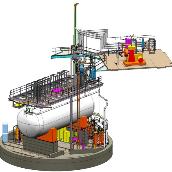
Upon installation of the sealed cryostat in its final location at the LArTF, 41 cm of spray-on, closed cell, polyurethane insulation was applied to the exterior of the cryostat, as shown in figure 6. At the LArTF, to avoid ground loops that could interfere with the LArTPC signals, the cryostat vessel is grounded in only one place, allowing it to act as a Faraday cage. This grounding scheme is explained further in section 7.1.
The vessel surface has 34 nozzle penetrations for cryogenic and electrical services, de-tailed in table4. All nozzles are sealed with feedthroughs, flanges, or pipes that are suitable
for operation at the nominal pressure and temperature of the cryostat.
Table 4. List of nozzle penetrations in the MicroBooNE cryostat, their function, and their flange/pipe type and outer-diameter dimension. CF=ConFlat flanges, RFWN=raised face weld neck flanges, SS = stainless steel pipe.
Nozzle ID Function Flange
N1A-N1K LArTPC Signal Feedthrough 356 mm CF
N2 LArTPC HV Feedthrough 203 mm CF
N3A-N3B Purity Monitor 203 mm CF
N4 Temperature Signals 152 mm CF
N5 Safety Vent 102 mm RFWN
N6A-N6B Vacuum Pump-Out 254 mm RFWN
N7 Condensor 76 mm SS
N8 Top Instrument Port 19 mm SS
N9 Bottom Instrument Port 19 mm SS
N10A-N10B Liquid Level Probe 19 mm SS
N11 Gas Circulation In 51 mm SS
N12 Gas Circulation Out 51 mm SS
N13 From LAr Filters 76 mm SS
N14 To LAr Pumps 51 mm SS
N15A-N15B Laser Calibration 70 mm CF
N16 PMT Signal Feedthrough 356 mm CF
N17 Spare 152 mm CF
N18 Temperature Signals 152 mm CF
N19 Spare 152 mm CF
3.2 Liquid Argon Purification Subsystem
The heart of the cryogenic system is the liquid argon purification subsystem. The primary requirement of this subsystem is to keep the level of electronegative contamination to be-low 100 ppt of O2 equivalent contaminants. This requirement is determined by the physics
needs of the experiment, namely the need to be able to reconstruct events at the longest drift distances in the LArTPC. In addition to the requirement on the electronegative con-tamination, the system must maintain the level of nitrogen contamination in the argon, by minimizing the leak rate from the atmosphere, at less than 2 parts per million (ppm) [27] to keep the quenching and attenuation of the scintillation photons in the argon to a minimum. The MicroBooNE argon purification subsystem consists of liquid argon pumps and filters that serve to circulate the argon and remove impurities (e.g. O2 and H2O) that
degrade the quality of the data collected by the active detectors. It should be noted that the filters do not remove N2 and so the ultimate N2 contamination is set by the quality
of the delivered argon. There are two pumps in the system arranged in parallel in order to allow for continuous recirculation while one pump is being serviced. Similarly, there are
PURITY MONITOR LAr PUMPS MOLE SIEVE & COPPER MOLE SIEVE & COPPER LAr SUPPLY N 2 V E N T PHASE SEPARATOR Ar/H2 SUPPLY HEATER N 2 V E N T VAPORIZER LAr DEWAR CRYOSTAT (with heaters and RTDs) CONDENSERS LN2 DEWAR VENT GAS ANALYZERS make-up gas pumps off mode pumps on mode Typically sampled from
pump discharge
Figure 7. Flow diagram of argon in MicroBooNE, showing direction of liquid and gaseous argon in the cryogenic system. Dashed lines represent gas lines, solid lines represent liquid lines, and yellow lines are for the filter regeneration. Gaseous argon from the cryostat is condensed and directed through the purification subsystem. Liquid argon drawn from the cryostat volume is directed into the purification subsystem.
two sets of filters arranged in parallel in the system. Figure7schematically depicts the flow of liquid and gaseous argon in the MicroBooNE cryogenic system.
The recirculation pumps are Barber-Nichols [28] BNCP-32B-000 magnetically-driven partial-emission centrifugal pumps. Each pump isolates the liquid argon from the electric motor by a magnetic coupling of the impeller to the motor. The impeller, inducer, and driving section of the magnetic coupling each have their own bearings that are lubricated by the liquid argon at the impeller. The motor is controlled by a variable frequency drive (VFD) that allows adjustment of the pump speed to produce the desired head pressure and flow within the available power range of the motor.
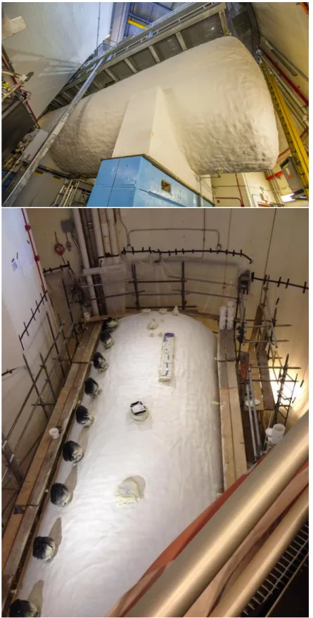
Each filter skid contains two filters, as depicted in figure 8, each having identically-sized filtration beds of 77 liters. The first filter that the argon stream enters contains a 4A molecular sieve supplied by Sigma-Aldrich [29] that primarily removes water contamina-tion but can also remove small amounts of nitrogen and oxygen. The second filter contains BASF CU-0226 S, a pelletized material of copper impregnated on a high-surface-area alu-mina, which removes oxygen [30] and to a lesser extent water. Because the oxygen filter will absorb water and thereby reduce its capacity for removing oxygen, it is placed after the molecular sieve. The oxygen-filtering material must be reduced to copper with the
Figure 8. Three-dimensional rendering of a MicroBooNE filter skid. The left drawing shows the full skid, while the right drawing shows a cut-away of the vessels.
procedure described below before it can remove oxygen from the liquid argon. The filters are insulated with vacuum jackets and aluminum radiation shields. The metallic radiation shields were chosen because the filter regeneration temperatures, described below, would damage traditional aluminized mylar insulation. Pipe supplying the filter regeneration gas is insulated both inside the filter vacuum-insulation space and outside the filter with Py-rogel XT, which is an aePy-rogel-based insulation [31] that can withstand temperatures up to 920 K.
The filters are initially activated and then regenerated as needed in situ using heated gas, by a procedure developed for the LAPD. The filters are regenerated using a flow of argon gas that is heated to 473 K, supplied by a commercial 500 liter liquid argon dewar. Once the argon gas reaches 473 K, a small flow of hydrogen is mixed into the primary argon flow and exothermically combined with oxygen captured by the filter to create water. Too much hydrogen mixed in with the primary argon flow would induce temperatures that are sufficiently high to damage the copper-based filter media. The damage is induced by sintering of the copper, which reduces the available filter surface area. To avoid such damage, precautions are taken to maintain a hydrogen fraction below 2.5% of the heated gas mixture. During the heated gas regeneration, five filter bed temperature sensors monitor the filter material temperature and the water content of the regeneration exhaust gas is measured. To remove any remaining trace amounts of water, the filters are then evacuated using turbomolecular vacuum pumps while they cool.
A particulate filter with an effective filtration of 10 microns, positioned between the cryostat and the filter skids, prevents any debris in the piping from being introduced into the cryostat. The particulate filter consists of a commercial stainless steel sintered-metal cylinder mounted in a custom cryogenic housing and vacuum jacket. Filtration is accom-plished by flowing liquid argon to the interior, then outward through the walls, of the sintered-metal cylinder. Flanges on the argon piping, along with flanges and edge-welded bellows on the vacuum jacket, allow removal of the particulate filter.
The argon purification piping is 2.54 cm diameter stainless steel that was pre-insulated by the manufacturer with 10.2 cm of polyurethane foam. During the fabrication process, all piping was washed with distilled water and detergent to remove oil and grease, then cleaned with ethanol. All valves associated with the argon-purification piping utilize a metal seal with respect to ambient air, either through a bellows or a diaphragm, to prevent the diffusion of oxygen and water contamination. The exhaust side of each relief valve is continuously purged with argon gas to prevent diffusion of oxygen and water from ambient air across the O-ring seal. Where possible, ConFlat flanges with copper seals are used on both cryogenic and room-temperature argon piping. Pipe flanges in the system are sealed using spiral-wound graphite gaskets. Smaller connections are made with VCR fittings with stainless steel gaskets.
3.3 Nitrogen Refrigeration
The cryostat and purification systems that contain the liquid argon are subject to heat load from the environment, as well as from the active detectors that have electrical power enabled. To keep these systems operating at a stable temperature and pressure, a liquid nitrogen refrigeration system is present to provide the necessary cooling power. The liquid nitrogen system contains two condensers that are arranged in parallel. One of these is utilized for normal operations and one serves as a backup on standby. Each condenser contains two liquid nitrogen coils, an inner and an outer, with the gas argon on the shell side. Typically only one coil is actively running and the second can be manually activated during situations where the system heat load is higher than usual. Each condenser is sized to handle a heat load of approximately 9.5 kW. With the vessel full of liquid argon and no pump or liquid argon circulation running, the condenser uses ∼2350 liters of liquid nitrogen per day, which equates to a 3.9 kW system heat load. With the recirculation pumps and the electronics in operation, the usage rate is about 3400 liters/day corresponding to a total heat load from the cryostat system of about 6 kW.
3.4 Controls and Purity Monitoring
MicroBooNE makes use of resistive thermal devices (RTDs) to measure temperatures through-out the experimental infrastructure. Twelve RTDs are located along the walls of the cryo-stat, and another ten RTDs are mounted inside screws attached to the structure of the LArTPC. Each of the filter vessels in the purification system contain nine RTDs. An inter-lock based on the RTDs within the filter vessels prevents overheating that could potentially occur during filter regeneration with heated argon-hydrogen gas.
Liquid argon contaminations ranging between 300 and 50 ppt O2 equivalent can be
measured using double-gridded ion chambers, henceforth referred to as purity monitors, immersed in liquid argon. The design of the purity monitors is based on the design presented by Carugno et al. [32]. A description of the purity monitors, the data-acquisition hardware and software used in LAPD can be found in [25]. MicroBooNE uses the same type of purity monitors, and the same data-acquisition hardware and software.
An estimate of the electron drift lifetime is made by measuring the fraction of electrons generated at the purity monitor cathode that subsequently arrive at the purity monitor anode (QA/QC) after a drift time t. The ratio of (QA/QC) is related to electron lifetime,
τ, such that
QA/QC = e−t/τ. (3.1)
Measurement of liquid argon purity in the MicroBooNE cryogenic system are provided by three purity monitors of various lengths. One purity monitor with a drift distance of 50 cm sits in a vessel just downstream of the filters and is used to monitor filter effectiveness. Two purity monitors, one with a drift distance of 19 cm and the other with a drift distance of 50 cm, sit within the primary MicroBooNE vessel at each end of the LArTPC. They are installed at different heights to allow purity measurements at different depths of the argon. 3.5 Initial Purification
The MicroBooNE cryogenic system was designed to allow the cryostat to go from containing atmosphere (and the detector) to containing high purity liquid argon (and the detector) without ever evacuating the cryostat. Such a process is considered essential to the de-velopment of multi-kiloton experiments where the cost of an evacuable cryostat would be prohibitive. While a successful test had been carried out in the LAPD [25], before Micro-BooNE, this process had never been performed in a cryostat with a fully instrumented large detector. A more complete description of the initial purification process with operational details is available in [33].
The process for preparing the cryostat for filling with liquid argon involves three stages. The first is the “piston-purge” stage where argon gas flows into the cryostat at its lowest point and the argon (being denser than the atmosphere) pushes the atmosphere out of the cryostat. The second stage is a recirculation phase where the argon-gas loop is closed and the argon flows through a water-removal filter to reduce outgassing of water from detector materials. The final stage is a cool down phase where the loop remains closed and the argon gas is cooled in a heat-exchanger and cools the detector to the point where the insertion of liquid argon will not damage the detector.
The so-called “piston-purge” was achieved using a single pipe for gas input at the bottom of the cryostat and an identical pipe for the output at the top; the pipes (referred to as “sparger” pipes) each have 4.76 mm diameter holes every 12.7 cm on both sides. Calculations of the mutual diffusion of argon and nitrogen suggested that a rate of 770.4 Nm3/hr. was adequate in avoiding turbulence and minimizing back-diffusion of the air [34].
A total of about 13 volume exchanges took one week and resulted in contamination levels of <10 ppm H2O, < 1 ppm O2 and < 1 ppm N2.
The recirculation phase used the same piping system as the piston-purge but at a significantly higher flow rate (3 cryostat changes/hr). As mentioned, the recirculation passed the gas through the water removal filter and over a period of three weeks, the water concentration was reduced to < 1 ppm. To counteract the increase in N2and O2 levels from
outgassing observed during this phase, (typically a rise of a few ppb/hr), a small fraction of the gas was vented and replaced with fresh argon.
The final stage involved cooling the cryostat and detector to prepare for filling with liquid argon. The TPC design imposed two requirements on the cooldown. One was that the input gas be no more than 20 K colder than the frame of the TPC to avoid wire-breakage since the massive TPC frame takes a long time to cool while the wires immediately adopt the input gas temperature and shrink, thereby increasing the stress on the wires. The second requirement was that the temperature difference between the top and bottom of the TPC be less than 20 K at any time to avoid warpage of the frame. A set of RTDs screwed into the TPC frame, RTDs in the inlet gas piping, and a set of RTDs attached to the anode side of the cryostat were used to measure and monitor the process. For the cooldown, the argon-gas was cooled using a three-pass counter-flow nitrogen heat-exchanger, and recirculated using the sparger pipes. The cooldown was declared complete after three weeks when the average temperature had reached 105 K and the temperature difference between the top and the bottom of the detector was <10 K. Upon reaching this state, the O2 level had
been reduced to 18 ppb and the H2O concentration had fallen to 22 ppb. These levels are
reduced by a factor of >800 in the liquid and presented an excellent environment for the start of filling.
4 Liquid Argon Time Projection Chamber
The MicroBooNE LArTPC drifts and collects charge to produce fine-grained images of the ionization that is liberated by charged particles traversing a volume of highly-purified liquid argon. This section describes the design and implementation of the LArTPC in the experiment.
The LArTPC is composed of three major structures: the cathode, the field cage, and the anode. A negative voltage is introduced via a feedthrough passing through nozzle N2 on the cryostat and applied at the cathode, which defines an equipotential surface. A uniform electric field between the cathode and the anode planes is established by a series of field rings connected by a voltage divider chain starting at the cathode and ending at the anode plane. Facing the cathode planes are the sense wire planes: two induction planes (referred to as the “U” and “V” planes) with wires oriented at ±60◦ from vertical, followed by one
collection plane (referred to as the “Y” plane) with vertically-oriented wires. The wires of the anode planes are the sensing elements that detect the ionization created by charged particles traveling through the LArTPC. Figure9depicts the assembled MicroBooNE LArTPC after insertion into the cryostat, showing details of the cathode, field cage, and anode plane. Table 5lists the main parameters of the MicroBooNE LArTPC, which will be described in detail in this section.
Table 5. MicroBooNE LArTPC design parameters and nominal operating conditions.
Parameter Value
#Anode planes 3
Anode planes spacing 3 mm
Wire pitch 3 mm
Wire type SS, diam. 150 µm
Wire coating 2µm Cu, 0.1µm Ag
Design Wire tension 6.9N ± 1.0N
#wires (total) 8256
#Induction0 plane (U) wires 2400
#Induction1 plane (V) wires 2400
#Collection plane (Y) wires 3456
Wire orientation (w.r.t. vertical) +60◦,-60◦,0◦ (U,V,Y)
Cathode voltage (nominal) -128 kV
Bias voltages (U,V,Y) -200 V, 0 V, +440 V
Drift-field 500 V/cm
Max. Drift Time, Cathode to U (at 500 V/cm) 1.6 ms
#Field-cage steps 64
Figure 8.1 The TPC inside the cryostat looking up the beamline from the downstream side. The cathode plane is on the right (beam-left). The wire planes and PMT array are on the left (beam-right). The TPC HV feedthrough is top-right (beam-left), and the TPC signal feedthroughs are shown top-left (beam-right).
A (2.33 m height)×(2.56 m width)×(10.37 m length) rectangular solid defines the 61.8 m3 active
volume of the TPC, which encompasses 86 tons of liquid argon when operational. The TPC cathode plane forms the vertical boundary of the active volume on the left side of the detector when viewed along the neutrino beam direction (“beam-left”). Three parallel vertical sense wire planes are mounted on the “beam-right” side of the active volume. The wires in the “Y” plane are oriented vertically, while wires in the “U” and “V” planes are oriented ±60 degrees, respectively, with respect to vertical. Ionization electrons drift from beam-left to beam-right, reaching in turn the U, V, and Y planes. The drifting electrons induce charge on the U and V induction plane sense wires as they drift by and deposit their negative charge on the Y collection plane sense wires.
The TPC HVFT occupies a position near the beam-left downstream top corner of the TPC. The TPC signal feedthroughs line up along the top beam-right boundary of the TPC.
Figure 9. Schematic diagram of the MicroBooNE LArTPC , depicted as it is arranged inside the cryostat.
4.1 Cathode
The cathode is assembled from 9 individual stainless steel sheets (Type 304, 2.3 mm thick) that are fastened to a supporting frame by hex-head stainless-steel button-screws. The outer edge of the cathode frame consists of round stainless steel tubes of 5.08 cm outer diameter and 3.18 mm wall thickness. Within this outer edge, square tubes with 5.08 cm × 5.08 cm cross-sectional area, and 3.18 mm wall thickness, are fastened together with hex-head button-screws, forming a support structure upon which the cathode sheets are attached. The individual components of the support structure are further welded together to eliminate sharp features from this high-potential surface. The exterior frame and support structure of the cathode, and also an interior view, are shown in figure10. The cathode plane sheets are shimmed according to survey data to make the cathode as flat and as parallel to the anode frame as possible, resulting in the two surfaces being parallel to within 0.0413◦. Flatness of
the cathode is evaluated relative to a best fit plane of survey data (more than 10000 survey points recorded with a laser tracker). The largest deviations of the cathode from the best fit plane are +6.6 mm and -6.5 mm. Approximately 55% of the measured survey points fall within +/-3 mm of the best fit plane, and more than 90% of the points fall within ±5 mm. Figure 11 shows the results of the survey, with deviations from flat represented as color-coded data extending away from the nominal plane of an ideal cathode.
Figure 10. Top: Exterior view showing the cathode frame and structural supports to which cathode sheets are fastened. Bottom: Interior view of cathode plane as viewed from the upstream end of the LArTPC , showing cathode sheets. Note that the cathode sheets are polished, so a reflection is is clearly present in this photograph.
Figure 11. Survey results showing the flatness of the cathode, as viewed from the interior (top) and exterior (bottom) sides, after shimming. Color scale extends from -6.498 mm (red) to +6.636 mm (blue).
4.2 Field Cage
The field cage encloses the volume between the cathode plane and the anode wire planes, and creates a region with a uniform electric field. The volume defined by the interior of the field cage, bounded by the anode and cathode planes, is referred to as the “active” volume. The field cage structure consists of 64 individual sets of thin-walled stainless steel tubes (2.54 cm OD, 0.51 mm wall thickness), each shaped into a rectangular loop framing the perimeter of the active volume. These 64 loops are mounted parallel to the cathode and anode planes, as shown in figure10, and are held in place by a G-10 rib support structure. Each field cage loop is electrically connected to its neighbors via a resistor divider chain (described in the following section), causing each loop to operate at a different electrical
potential, which in turn maintains a uniform electric field between the cathode and anode planes. For a nominal -128 kV cathode voltage, the difference in potential between adjacent field cage loops is 2 kV, ramping down the total potential in equidistant steps from cathode to anode. The distance from center-to-center of adjacent field cage loops is 4.0 cm.
Each field cage loop is assembled from 2.07 m long vertical pipes on the upstream and downstream ends of the LArTPC , and on the top and bottom from two 5.18 m long horizontal pipes connected by a stainless steel coupling in the center. Each tube has venting holes approximately every 15 cm to allow for effective purging from atmosphere and to avoid any trapped volumes.
The four corners of each field cage loop are curved with a radius of 5.24 cm. Each corner is formed by three parts: two couplings and an elbow, shown in figure 12. The couplings make the connections between the pipes and the elbow. The thin-walled tubes and elbows slip-fit over the ends of the couplings with a 2.2 cm overlap. Each coupling has two 6-32 NC tapped holes and the connections to the adjoining pieces are made by hex-head button-screws and split-ring lock washers with no teeth.
In order to avoid electrical breakdown between the inner cryostat surface and field cage parts at high potential on or near the cathode, the electric field strength is minimized at the corners and edges of the field cage. Loops 0, 1, and 2 are each designed differently than the other field cage loops. Loop 0 is a special case in that it is made from larger diameter piping of 5.08 cm OD, and frames the cathode and also acts as its mechanical support. It operates at the same electrical potential as the cathode plane sheets attached to it. Loop 0 has a slightly smaller area than the other field cage loops, as shown in figure 12. Loop 1 is the first of the 64 loops in the field cage with 2.54 cm pipe OD. It surrounds the cathode plane and operates at cathode potential. The elbow of loop 1 has a specially designed geometry in order to minimize the electric field potential. The elbow of loop 2 has a larger radius of curvature than the standard elbows, also for the purpose of minimizing the electric field potential. For all three of these loops (loop 0, 1, and 2), connections at corners and joints are made by welding instead of screws to avoid sharp edges that would result in higher electric fields and greater chance of electrical breakdown.
Another precaution to minimize the electrical field between the loops and the cryostat surface is the positioning of the coupling screws: for the first 20 loops, the screws are positioned on the sides facing the screws of the neighboring loops instead of facing inward to the LArTPC active volume and outward toward the grounded cryostat surface. Hex-head button-screws and lock washers are also used here in order to minimize sharp metal edges.
Figure 13 shows the simulated electric field values inside the MicroBooNE LArTPC , and some of the surrounding volume inside the cryostat, when the cathode is set to an operating voltage of -128 kV.
4.2.1 Resistor Divider Chain
A resistor divider chain installed across the field cage loops steps the voltage down in magnitude from the cathode plane to the anode wire plane in equal steps. For a nominal value of -128 kV on the cathode, this results in a potential difference of 2 kV between each
Loop 0
Loop 1
Loop 2
Loop 3
Loop 4
Loop 5
Figure 12. Photograph of the field cage during construction, with loops 0 (cathode) through 5 labeled. Field cage loops closest to (and including) the cathode are modified to reduce sharp edges that would result in higher electric fields.
pair of loops. The value of the equivalent resistance between loops within the divider chain was chosen to be low enough such that the current flow through the divider circuit is much greater than the signal current flowing through the LArTPC . The signal current in our case is dominated by the free ionization produced by the cosmic ray flux, and is estimated to be <50 nA. An equivalent resistance of 250 MΩ between each pair of field cage loops, corresponding to a current flow of 8 µA, was chosen.
The voltage divider chain is mounted on the inside of the field cage at the upstream end of the detector. The couplings at the top corner of each field cage loop have additional holes facing the inside of the field cage, where the resistors are mounted. On the first 16 field cage loops, pairs of Metallux HVR 969.23 499 MΩ resistors (rated to 23 W, 48 kV in air) are mounted electrically in parallel to establish the beginning of the voltage divider
Figure 13. Cross-section view showing the electric field simulation inside the field cage when the cathode is set to a voltage of -128 kV. Loop 0 is represented by the larger diameter circle on the left of the image. The legend shows the absolute values of electric field modulus in units of V/m.
chain. On the remaining loops, four thick-film Ohmite Slim-Mox 104E metal-oxide epoxy-coated resistors with a lower power and voltage rating (1.5 W, 10 kV in air) are mounted in parallel, per loop. Extensive testing was done on these two types of resistors [35].
For the loops with the Slim-Mox resistors, printed circuit boards span across eight field cage gaps and therefore have eight 250 MΩ resistances in series, shown in figure 14. The electrical connection between the boards and each field cage loop is made by metal contact pads on the back side of the boards, held in electrical contact with the field cage tube by a hex-head button-screw and lock washer.
While the designed operating voltage difference across each resistor in the detector is 2 kV with a power flow of 4 mW, there is a slight possibility that the voltage drop and power could temporarily exceed the rating of the resistors in the case of discharge between the cathode plane or field cage loops and the cryostat wall, through the bulk liquid argon. Recent studies [36] have shown that the value of the minimum breakdown electrical field decreases with the increasing argon purity; for purities as high as that required in the MicroBooNE detector, breakdown has been observed at electric fields as low as 40 kV/cm. The field cage behaves like a capacitance network at high frequencies. Based on mea-surements and simulations, the total energy stored inside the field cage when fully charged is estimated to be approximately 24 J. In the case of a discharge between the cryostat and the cathode or one of the field cage loops close to the cathode, simulations show that voltages of up to 80 kV peak, with a discharge time constant of a few seconds, can develop across the resistors. The observed peak voltages in such discharge scenarios decrease the further the breakdown occurs from the cathode, such that discharges occurring between the cryostat and field cage loops 32 through 63 do not exceed the 10 kV rating of the resistors. Two strategies have been implemented to protect the resistors nearest the cathode from
Figure 14. The Ohmite Slim-Mox 104E resistors arranged in parallel sets of four on printed circuit boards that span eight field cage tubes.
damage due to discharge. The first is the use of the Mettalux resistors on the first 16 loops given their higher voltage rating of 48 kV as compared to the Slim-Mox resistors on the remaining loops.
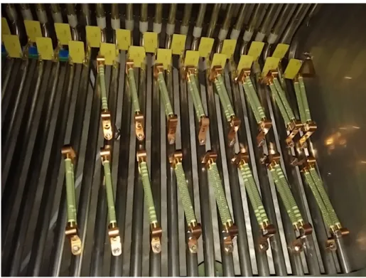
Since the Metallux HVR 969.23 resistors are significantly larger physically than the loop-to-loop distance, they are mounted diagonally between each pair of field cage loops. They are held by copper brackets, which are attached to studs welded onto the field cage tubes, shown in figure15.
The second protective measure is installation of surge protection circuits on field cage loops 1 through 32. The chosen surge protection devices are designed to short the circuit in the case of a voltage spike, which protects any other electrical components installed in parallel. Below their clamping voltage, they exhibit a very high resistance and do not influ-ence the circuit. The behavior of Gas Discharge Tubes (GDTs) and varistors in liquid argon has been studied extensively for application in the MicroBooNE field cage [37]. The surge protection device chosen is a Panasonic ERZ-V14D182 varistor with a clamping voltage of 1700 V. In order to obtain a very high resistance in normal operation and a clamping volt-age above the 2 kV in normal operation mode, three of these devices are mounted in series across a block of four Slim-Mox 104E or two Metallux 969.23 resistors. These additional varistor boards make electrical contact with the field cage via brass mounting brackets that are fastened to the field cage with button-head screws, as shown in figure16.
Figure 15. The Metallux HVR 969.23 resistors mounted on the 16 field cage loops closest to the cathode.
Figure 16. Surge-protecting varistors (small black disks in the photograph) are installed in parallel with the voltage divider resistors for the first 32 field cage loops. Here, they are shown mounted on small boards in sets of 3, and attached to the field cage by means of 6-32 hex-head button-screws.
Figure 17. Rendering of the anode frame assembly. The C-channel is depicted in gray, and the adjustable tensioning bar assembly is shown in orange.
4.3 Anode Planes
The anode frame holds the induction and collection plane sense wires at tension and provides overall structural support for the beam-right side of the LArTPC. Individual sense wires for all anode planes are held in place by wire carrier boards, which are printed circuit board assemblies that position the wires as well as provide the electrical connection to the electronic readout system of the experiment.
4.3.1 Mechanical structure
The anode frame is comprised of a stainless steel C-channel hosting adjustable tensioning bars to which the wire carrier boards are attached. The C-channel and tensioning bar assembly is depicted for one corner of the anode frame in figure 17. Wire carrier boards attach to precision alignment pins distributed along the length of the tensioning bars. 4.3.2 Wire winding and quality assurance
The three anode planes are constructed from wire carrier boards that have individually-prepared wires attached to them in groups of 16 (for the U- and V- angled planes) or 32 (for the vertical Y-plane). Consistent quality in wire preparation was achieved by a semi-automated winding machine, which terminated the ends of each wire via wrapping around 3 mm diameter brass ferrules as shown in figure 18. The wire termination method via wrapping around a brass ferrule similar to that used in the ICARUS T600 detector.
Each wire was tested for strength on a tensioning stand where a load of 2.5 kg (more than 3 times the nominal load of 0.7 kg) was applied for 10 minutes, ensuring that the wire preparation did not leave any weaknesses that could result in a breakage. Upon successful
Figure 18. Photograph of the wire termination on the brass ferrules. Each ferrule is 3 mm in diameter, and 1.5 mm thick.
Figure 19. Photograph of a collection plane wire carrier board that has been filled with wires, but has not yet had the cover plate installed.
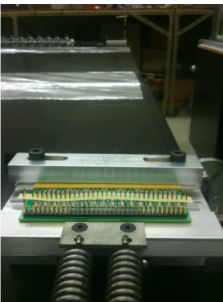
completion of the quality assurance testing, each wire was placed onto a wire carrier board, shown in figure 19.
When installed on the wire carrier boards, the wires make contact with gold pins which are connected to a trace that routes to the cold electronics. Once the wire-carrier board was filled with wires, a cover plate was installed and press-fit rivets were installed to hold the assembly together. The assembled wire carrier board was then placed onto a tension stand, to reapply a 2.5 kg tension/wire to the whole board for 10 minutes. This is to ensure that the wires were not weakened during the board assembly process. The tension stand is depicted in figure20. A comprehensive description of the MicroBooNE wire preparation and associated quality assurance studies can be found in [38].
Figure 20. Photograph of a collection plane wire carrier board on the tension stand.
4.4 Parts Preparation
The majority of the parts that make up the LArTPC are either stainless steel or G-10. These two material types, as well as any others used in the LArTPC, were tested in the Fermilab Materials Test Stand (MTS) [39], whose purpose was to investigate the suitability of materials for use in LArTPCs. The MTS confirmed that none of the materials used in the LArTPC assembly would contaminate the liquid argon. Before assembly, all LArTPC parts were cleaned according to the procedures described in the following sections.
4.4.1 Cleaning stainless steel
The delivered stainless steel parts were often greasy due to machining, and those with holes or interior cavities generally had a significant amount of trapped metal shavings due to the machining processes. Many of the pieces also had markings from permanent ink pens, dirt smears, rust spots, and/or dried oil from machining. These pieces were scrubbed with ScotchBrite 7447 general-purpose hand pads before cleaning.
Parts that were small enough to fit in an ultrasonic bath were prepared according to the following prescription. A pre-rinse with tap water was performed to remove particulate matter, followed by deburring of sharp edges. The first ultrasonic wash was 15 minutes in heated distilled water with a 3% solution of Citranox acid detergent [40]. After a first rinse in distilled water, a second ultrasonic wash was performed, again for 15 minutes, but using heated distilled water with a weak solution of Simple Green detergent [41]. A second rinse
in distilled water was performed, followed by a final rinse in a fresh bath of distilled water. The parts were then wiped dry with lint-free cloths, air dried completely, and wrapped in plastic film for storage.
Stainless steel parts that were too large to fit in the ultrasonic bath were prepared by a simpler prescription out of necessity. A pre-rinse with tap water was followed by deburring to remove sharp edges. Both the first and second washes were done with tap water and a weak solution of Simple Green detergent, scrubbing with brushes and lint-free sponges. Two tap water rinses were done, and the parts were then wiped dry with lint-free cloths. As a final additional step, each part was wiped with 200-proof ethyl alcohol, and then air dried completely. These parts were also wrapped in plastic film for storage.
4.4.2 Cleaning G-10
G-10 is known to absorb large quantities of water, which would outgas in the argon and could inhibit reaching the required argon purity in the detector. For this reason all G-10 parts were cleaned and then baked to remove moisture. The largest G-10 parts on the detector are beams that span the distance between the cathode and anode. These were washed in 1900-liter ultrasonic baths that are overseen by Fermilab Accelerator Division, typically used for cleaning large sections of accelerator beam pipes. An initial pre-wash was done with tap water to remove as much particulate matter as possible, since the machining process left a large amount of dust on the machined edges. Pieces were then placed in the ultrasonic bath with heated deionized water and a 2% solution of Elma Clean 65 (EC 65) neutral cleanser [42]. Two ultrasonic bath rinses were performed, and the pieces were then sealed in plastic bags with clean dry nitrogen gas. In order to remove the absorbed water, the large G-10 parts were then transported to the Fermilab Technical Division where they underwent an outgassing procedure to remove any remaining absorbed moisture. They were baked in a large oven under vacuum until a plateau in the outgassing rate was reached, as reported by a monitor inside the oven. Upon completion of the outgassing procedure, the parts were resealed in plastic bags for storage.
4.5 Assembly
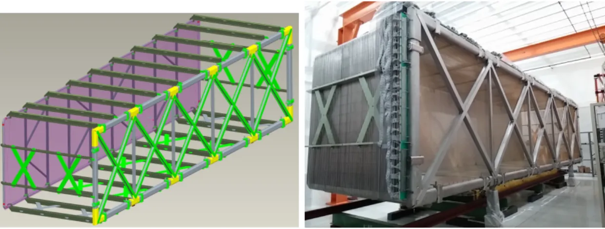
The full mechanical structure of the LArTPC is shown in figure 21, with the left image depicting the cathode frame as semi-transparent to show the support structures on which the cathode sheets are attached. The anode frame is on the right of this image, with I-beams configured in a crossed pattern to maintain the shape and rigidity of the outer C-channel structure. Ribs of G-10 connect the anode and cathode, electrically isolating them from each other while also providing mounting holes to hold in place each of 64 field cage loops that define the active volume of the LArTPC. The field cage loops are visible in the photograph on the right of figure 21.
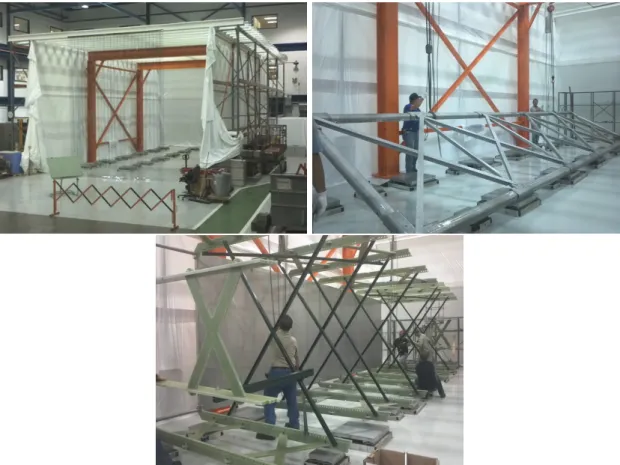
Assembly was done inside of a clean tent, shown on the top left in figure 22, on a flat surface made up of adjustable-height metal platforms that were installed on the assembly room floor. These platforms were leveled to better than 0.5 mm before beginning assembly. The anode frame was the first part of the detector to be assembled on this surface, shown on the top right of figure 22. It was temporarily placed aside, and the cathode frame was
Figure 21. Left: Rendering of the full LArTPC frame assembly. Right: Assembled LArTPC after wire and electronics installation.
assembled on the same set of platforms along with the G-10 ribs, which stood vertically with the help of temporary unistrut support pieces. The combined cathode and G-10 frame was then lifted and rotated to the proper orientation, with G-10 ribs extending horizontally from the cathode to the anode, as shown on the bottom in figure 22. Finally, the anode frame was brought back over and attached to the G-10 ribs, and the stainless steel tubes that make up the field cage loops were fed through the holes in the G-10 ribs to complete the mechanical structure of the LArTPC.
4.5.1 Wire installation and tension measurements
During detector assembly, the completed wire carrier assemblies (consisting of wires and supporting carrier boards on either end) were manually installed onto the adjustable ten-sioning bars residing in the C-channel of the supporting anode frame. A team of two people installed each assembly onto the anode frame. The collection plane was the first installed, followed by the middle induction plane, and then finally the inner induction plane. Once all three anode planes were completely installed, the tensioning bars were adjusted and a survey was taken of the tension of all anode wires. Tension was set according to the design criteria that it be small enough to prevent wire breakage during cool down and large enough to limit the maximum wire sag due to gravity to under 0.5 cm for any 5 m long U or V wire. Tension was recorded through measurement of the resonant frequency of a laser beam reflected from a plucked wire and incident on a photodiode connected to a spectrum ana-lyzer program [43]. The tension measuring equipment was developed and produced by the University of Wisconsin Physical Sciences Laboratory. The tensioning bars were adjusted iteratively until the surveyed tension of all wires was within a range, approximately ±1.0 N of the nominal value of 6.9 N, where no single wire was too taught or loose to create detector performance issues. Figure 23 shows the final surveyed tension of the wires for each plane.