HAL Id: hal-02112187
https://hal.archives-ouvertes.fr/hal-02112187
Submitted on 26 Apr 2019
HAL is a multi-disciplinary open access
archive for the deposit and dissemination of
sci-entific research documents, whether they are
pub-lished or not. The documents may come from
teaching and research institutions in France or
abroad, or from public or private research centers.
L’archive ouverte pluridisciplinaire HAL, est
destinée au dépôt et à la diffusion de documents
scientifiques de niveau recherche, publiés ou non,
émanant des établissements d’enseignement et de
recherche français ou étrangers, des laboratoires
publics ou privés.
through robotized wire deposition
Maxime Chalvin, Sébastien Campocasso, Thomas Baizeau, Vincent Hugel
To cite this version:
Maxime Chalvin, Sébastien Campocasso, Thomas Baizeau, Vincent Hugel. Automatic multi-axis path
planning for thinwall tubing through robotized wire deposition. 12th CIRP Conference on Intelligent
Computation in Manufacturing Engineering (CIRP ICME), Jul 2018, Gulf of Naples, Italy. pp.89-94,
�10.1016/j.procir.2019.02.017�. �hal-02112187�
1
Automatic multi-axis path planning for thinwall tubing
through robotized wire deposition
Maxime Chalvin
a,*, Sébastien Campocasso
a, Thomas Baizeau
b, Vincent Hugel
aaUniversité de Toulon, COSMER, Toulon, France
bPoly-Shape, 235 rue des Canesteu, ZI La Gandonne, 13300 Salon de Provence, France
* Corresponding author. Tel.: +33-494-142-360. E-mail address: [email protected]
Abstract
Metal wire deposition is a promising additive technology to produce low-cost near shape blanks for large and complex parts. Combined with robotic arms, multi-axis deposition presents new opportunities and challenges regarding deposition path planning and tool axis determination, especially to avoid support material use.
In this work, an automated algorithm that calculates the deposition path, the tool orientations and the local inter-layer distances is presented. Then, an adaptive travel speed strategy is applied to adjust the bead morphology to the local layer height. Finally, two multi-axis deposition strategies are compared numerically and experimentally for manufacturing cantilever thinwall tube geometries.
Keywords: Additive manufacturing; CAM; Tubing; Robot; Fused deposition
1. Introduction
Metallic additive manufacturing technologies like Direct Metal Deposition (DMD) (e.g. Wire and Arc Additive Manufacturing (WAAM) or Laser Metal Deposition (LMD)) are able to produce near net shape blanks to reduce the Buy-to-Fly ratio (BTF). Reducing the BTF ratio is the best way to produce cheaper complex parts [1,2].
Even if only rough workpieces can be obtained by DMD, the cost and the production time of parts can be reduced by minimizing machining allowances. That is why the deposited material must be minimized and supports limited as much as possible. However, supports are necessary for cantilevered geometries when using classic parallel layer paths obtained by z-level slicing (or 2.5D path).
To optimize the production of these kinds of geometries, the deposition system can be coupled with 5-axis CNC or 6 axis robots. Thus, the deposition paths are not yet restricted to 2.5D but may be 3D with several orientations. Thereby
manufacturing of cantilevered geometries without support becomes possible.
Some strategies are based on a decomposition in different topological entities with 2.5D paths specific to each sub-volume [3,4,5]. This technique allows the fabrication of complex geometries divided in straight or slightly curved sub-volumes as shown in Fig. 1.
Fig. 1. (a) Part with cantilevered entities; (b) Sub-volumes division; (c) 2.5D path for every sub-volumes [3]
2 Fig. 2. (a) CAD of the part; (b) Adaptive building direction (blue vector) [3];
(c) Example of 3D path perpendicular to the neutral axis for a tube [6]
But it is also possible to do the same thing to a unique volume, Fig. 2(a) and 2(b), with different building directions and a set of 2.5D paths for every sub-division.
The solutions presented in Fig. 1 and Fig. 2(a) and 2(b) do not use all the capabilities of the multi-axis CNC/robot. Some 3D paths with specific building direction for each layer are already proposed by Shamsaei et al. [6] for thinwall tubes with layers perpendicular to the neutral axis (Fig. 2(c)).
Nevertheless, this kind of strategy presents a risk of tool collision and deposition defects (material falling) because of the variable distance between the layers.
The purpose of this paper is to present new path planning strategies adapted for tubing geometries, applied to a quarter of a torus as a study case. First the strategy proposed by Shamsaei et al. [6] is analyzed, followed by the presentation of a new method of 3D paths generation. Then an automatic algorithm for building direction generation is detailed. Finally, an experimental comparison of these different strategies is shown.
Nomenclature
r radius of the tube
R bending radius of the tube
Δlayer distance between two successive layers
𝑡⃗ local vector tangent to the path 𝑛⃗⃗ local vector normal to the surface 𝑏⃗⃗ local vector build direction
2. Path planning and geometrical analysis
In this paper, the part under study is a thinwall quarter of a torus (as seen in Fig. 3(a)). This cantilever geometry is mathematically defined by the equations (1).
𝑋 = (𝑅 + 𝑟. cos(𝑣)). cos(𝑢) − 𝑅 𝑌 = 𝑟. sin(𝑣) 𝑍 = (𝑅 + 𝑟. cos(𝑣)). sin(𝑢)
(1)
Fig. 3. (a) CAD of the studied part; (b) Mathematical parameterization
Fig. 4. 3D path perpendicular to the neutral axis
2.1. 3D path perpendicular to the neutral axis
It is possible to apply a similar path to the one described by [6] for to this part. For this purpose, the interlayer distance Δlayer
is defined along the neutral axis between two layers, Fig. 4. For the next path figures (Fig 4,6,7,8,10) Δlayer is set to 3 mm
for better visibility.
The result presented in Fig.4 corresponds to the iso parametric curves of the torus and shows that the distances between two successive layers of the path is not constant. A map of the local inter-layer distances is presented in Fig. 5.
The local inter-layer variation is about ± 30 %. This variation can involve some deposition issues because of a need of more or less material according to the location. One method described by Ren et al. [4,6] consists in depositing a uniform layer and then machining it to respect the local inter-layer distance. This method needs a hybrid system (additive manufacturing and machining in the same device) and also increases the manufacturing time and the quantity of material used to produce the part. Another method consists in a variation of the bead section [6,7,8] to adapt the deposit to the local inter-layer distance. Some studies [9,10,11,12] show that the bead height and width vary in a non-linear way with the deposition parameters and when the bead section increases, the height increase is smaller than that of the width. The deposit management with less need of material can ease the production because of a best control of the bead section.
3
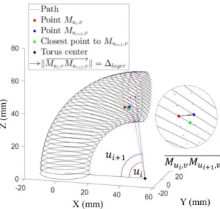
The generation of the non-planar 3D path is based on a new local definition of the Δlayer parameter. For this strategy, Δlayer is
defined not along the neutral axis but between 2 points with the same v parameter. The ui+1 parameter is so dependent on ui,
Δlayer and the v parameter, as expressed in equation (2).
‖𝑀⃗⃗⃗⃗⃗⃗⃗⃗⃗⃗⃗⃗⃗⃗⃗⃗⃗⃗⃗⃗⃗⃗⃗⃗⃗‖ = Δ𝑢𝑖,𝑣𝑀𝑢𝑖+1,𝑣 𝑙𝑎𝑦𝑒𝑟 𝑢𝑖+1= 𝑢𝑖+ arccos (1 − 𝛥𝑙𝑎𝑦𝑒𝑟2 2.(𝑅+𝑟.cos(𝑣))2) 𝑢0= 0 (2)
It is to be noted that the local inter-layer distance on the 3D path (Fig. 6) is still heterogeneous like the one for the 3D path perpendicular to the neutral axis.
However, the geometrical analysis in Fig. 7 shows that the local inter-layer distance is only lower than Δlayer with less
variation than in the previous case: the biggest gap is around - 46 % compared to the 60 % global variation of the 3D perpendicular to the neutral axis path.
This path presents a lower global distance variation. This can involve potentially better mechanical characteristics [6,13,14] by minimizing process parameter variation. As it is easier to manage deposit with less material, this kind of path may lead to parts with less manufacturing defects.
Two different paths have been introduced to produce the studied part. But tool orientations for the deposition also need to be defined. That is why an automatic tool orientation method building is presented in the next section.
Fig. 6. Non-planar 3D path
Fig. 7. Local inter-layer distance variation along the path 3. Automatic tool orientation generation
To avoid support material, the gravity orientation of the workpiece is an important factor. Moreover, when performing DMD, different angles between the deposition tool direction and the deposition direction can affect the drop transfer and the deposition quality [15]. To determine the tool orientation, a local build-basis is defined from the path geometry and then two tilting angles are set to have the tool orientation.
3.1. Methodology
The local building direction is determined normal to the path and tangent to the workpiece using a tangent to the path vector 𝑡⃗ and a normal to the surface vector 𝑛⃗⃗.
First of all, the 𝑡⃗ vector is determined as being
𝑀𝑢,𝑣−1𝑀𝑢,𝑣+1
⃗⃗⃗⃗⃗⃗⃗⃗⃗⃗⃗⃗⃗⃗⃗⃗⃗⃗⃗⃗⃗⃗⃗⃗⃗⃗⃗⃗. Secondly, the 𝑛⃗⃗ vector is determined as being the normal to the surface. To determine 𝑛⃗⃗ at the 𝑀𝑢,𝑣 point, two
facets are created, except for the first and the last layer, as graphically explained in Fig. 8.
First facet, lower facet, is built with the following points:
𝑀𝑢,𝑣−1
𝑀𝑢,𝑣+1
Closest point to 𝑀𝑢,𝑣 of the lower layer
Second facet, upper facet, is built with the following points:
𝑀𝑢,𝑣−1
𝑀𝑢,𝑣+1
Closest point to 𝑀𝑢,𝑣 of the upper layer
The normals to these facets are calculated and the normal to the surface at 𝑀𝑢,𝑣 point is the mean vector of the two previous
normal vectors.
For the first layer, the normal to the surface at the point 𝑀𝑢,𝑣
is the normal to the upper facet. For the last layer, the local normal is the same than the lower facet.
4
Once the normal is built, it is possible to build an orthonormal basis (𝑡⃗, 𝑛⃗⃗, 𝑏⃗⃗), as shown in Fig.9. The 𝑏⃗⃗ vector is the local build-direction vector. To have an upwards 𝑏⃗⃗ vector, the 𝑛⃗⃗ vector is outside or inside matter according to the 𝑡⃗ direction.
The tool orientation 𝑇⃗⃗ is obtained by tilting the build direction vector in two directions: a tilt angle 𝜃𝑛 in the feeding
plane and a tilt angle 𝜃𝑡 in the orthogonal plane (Fig. 10).
The different tilts are determined with the deposition conditions and the local geometry. The goal is ultimately to have the better deposition conditions while avoiding collisions.
Fig. 9. Local orthonormal basis (𝑡⃗, 𝑛⃗⃗, 𝑏⃗⃗)
Fig. 10. Tool vector defined with tilting from the build-direction vector
3.2. Application to different paths
The automatic local build-direction generation is applicable to any path, as illustrated in Fig. 11.
The methodology proposed in section 3.1 can be applied to any trajectory without knowing the exact mathematical definition of the surface. However, in this case, as the path is analytically defined, it is possible to compare the analytical generation of the build-direction with the numerical method. The precision of the numerical method depends on the discretization of the path. For a discretization set of 26 points per millimeters, the numeric build-direction is, on average, in a cone with a half-angle of 0.15° for the 3D path perpendicular to the neutral axis and in a cone with a half-angle of 0.22° for the non-planar 3D path.
Fig. 11. Automatic build-direction generation applied to different paths; (a), (c) 3D perpendicular to the neutral axis path; (b), (d) Non-planar layered
3D path Fig. 8. Calculation method of the normal vector 𝑛⃗⃗
5
But there is no thermal issues and the deposition conditions are easier compared to a MIG/MAG utilization. Fused deposition is even so a good way to improve the different paths before using a DMD system.
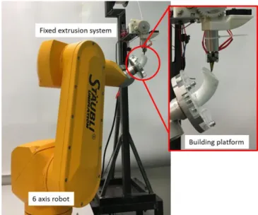
4.1. Experimental device
The experimental device (Fig.12) consists of a RX60BL Stäubli robot and a custom polymer deposition system. The configuration of the device is a fixed extrusion system and a moving building platform which receives the part. This configuration makes it possible to have a fixed gravity influence on the extruded material. Moreover, this one minimizes the need of joints, limiting them to 5, to reach the different tool/workpiece configurations.
The deposition system presented in Fig.12 has been designed to maximize symmetry and avoid a maximum of collisions (between the part and the nozzle or between the building platform and the deposition system) with a remote fan and a vertical radiator. Moreover, it allows a large offset between the wire feed system and the nozzle.
The device configuration involves a non-casual utilization for the robot. Indeed, if the robot is controlled in a conventional way, the speed at the deposition point 𝑉⃗⃗⃗⃗⃗⃗⃗⃗⃗⃗⃗⃗⃗⃗⃗⃗⃗⃗⃗⃗⃗ depends on 𝑑𝑒𝑝𝑜𝑠𝑖𝑡𝑖𝑜𝑛
the cartesian speed at the controlled point (𝑉⃗⃗⃗⃗⃗⃗⃗⃗⃗⃗⃗⃗⃗⃗⃗⃗⃗⃗⃗⃗⃗), the 𝑐𝑜𝑛𝑡𝑟𝑜𝑙𝑙𝑒𝑑
rotation speed 𝑁⃗⃗⃗ and the distance d between the deposit point and the controlled point, Fig.13.
To avoid this speed control issue, the kinematic transform of the robot controller is used: the speed steering is made with a tool gauge variation and a programmed speed at the desired point. Path points are declared in the program with the nozzle cartesian coordinates and different tool gauges, corresponding to the path coordinates in the part coordinate system.
Fig. 12. Experimental device
Fig. 13. Schematic speed control
4.2. Results comparison
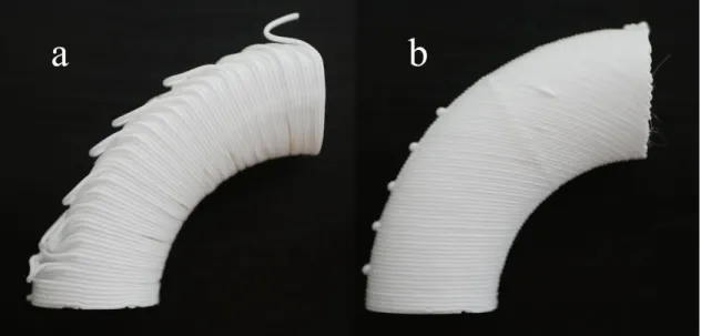
As visible in Fig. 14, 2.5D path without using support is not compatible with the thinwall torus, confirming the interest for 3D paths. The experimental manufacturing results using the two previously paths are shown in Fig.15.
For the fabrication with the 3D paths, an adaptive travel speed strategy is applied with a linear law according to the local inter-layer distance. However, with the 3D perpendicular to the neutral axis path, in the highest distance areas, the deposition domain is no longer respected and there are manufacturing defects. On the contrary, with non-planar 3D path, the deposition quality along the path is better and there are few manufacturing defects.
Some defects can be explained because of an incorrect bead morphology variation law. The law used is uniquely based on a travel speed variation whereas it is also possible to manage the bead section with the wire speed rate and potentially the extrusion temperature.
Others defects can be explained because of the robot dynamics. In the areas with important variation of the tool vector, many joints must be used and the speed may not be respected during the different rotations at the path point.
6
The over deposition material “balls” is due to a technological limitation of the robot: the internal memory is too short to store the full program and so, the program is divided in several sub-programs. The robot stops its movement while charging the sub-program and the deposition inertia generates these over depositions before the wire feed is stopped.
5. Conclusions
From the experimentations, a first conclusion is that additive manufacturing of bended tubes without support is only possible with multi-axis 3D paths. With these paths, as the local inter-layer distance varies, the bead morphology must be continuously adjusted during the fabrication. But this adjustment must be inside the capabilities of the manufacturing process.
In this paper, a new way of generating 3D path has been presented, the non-planar one, able to produce bended tube without support thanks to a reduced inter-layer distance variation compared to the 3D path perpendicular to the neutral axis. An algorithm has also been developed to automatically generate a local build direction allowing to keep the workpiece under the deposit to avoid material falling.
Future expectations are related to the improvement of the bead section law, the development of automatic path generation for any kind of tubes and the applications in metal deposition with similar experimental device configurations.
References
[1] Cunningham, C.,Wikshåland, S., Xu, F., Kemakolam, N., Shokrani, A., Dhokia, V., and Newman, S. Cost modelling and sensitivity analysis of wire and arc additive manufacturing. Procedia Manufacturing 2017, Volume 11 :650–657.
[2] Williams, S. and Martina, F. Wire + arc additive manufacturing vs. traditional machining from solid : a cost comparison. Technical report. Welding Engineering and Laser Processing Centre 2015, Cranfield University.
[3] Ding, D., Pan, Z., Cuiuri, D., Li, H., Larkin, N., and Van Duin, S. Automatic multi-direction slicing algorithms for wire based additive manufacturing. Robotics and Computer-Integrated Manufacturing 2016, Volume 37 :139– 150
[4] Ren, L., Sparks, T., Ruan, J., and Liou, F. Process planning strategies for solid freeform fabrication of metal parts. Journal of Manufacturing Systems 2008, Volume 27(4) :158–165.
[5] Ruan, J., Eiamsa-ard, K., and Liou, F.W. Automatic process planning and toolpath generation of a multiaxis hybrid manufacturing system. Journal of Manufacturing Processes 2005, Volume 7(1) :57–68.
[6] Shamsaei, N., Yadollahi, A., Bian, L., and Thompson, S. M. An overview of direct laser deposition for additive manufacturing; part II : Mechanical behavior, process parameter optimization and control. Additive Manufacturing 2015, Volume 8 :12 – 35
[7] Ma, W., But, W.-C., and He, P. Nurbs-based adaptive slicing for efficient rapid prototyping. Computer-Aided Design 2004, Volume 36(13) :1309– 1325
[8] Wulle, F., Coupek, D., Schäffner, F., Verl, A., Oberhofer, F., and Maier, T. Workpiece and machine design in additive manufacturing for multi-axis fused deposition modeling. Procedia CIRP 2017, Volume 60 :229 – 234. [9] Ding, D., Shen, C., Pan, Z., Cuiuri, D., Li, H., Larkin, N., and van Duin, S.
Towards an automated robotic arc-welding-based additive manufacturing system from CAD to finished part. Computer-Aided Design 2016, Volume 73 :66–75.
[10] Li, F., Chen, S., Shi, J., Tian, H., and Zhao, Y. Evaluation and optimization of a hybrid manufacturing process combining wire arc additive manufacturing with milling for the fabrication of stiffened panels. Applied Sciences 2017, Volume 7(12) :1233
[11] Xiong, J., Zhang, G., Hu, J., and Wu, L. Bead geometry prediction for robotic GMAW-based rapid manufacturing through a neural network and a second-order regression analysis. Journal of Intelligent Manufacturing 2014, Volume 25(1) :157–163.
[12] Urbanic, R., Hedrick, R., and Burford, C. A process planning framework and virtual representation for bead-based additive manufacturing processes. The International Journal of Advanced Manufacturing Technology 2017, Volume 90(1-4) :361–376.
[13] Spencer, J., Dickens, P., and Wykes, C. Rapid prototyping of metal parts by three dimensional welding. Proceedings of the Institution of Mechanical Engineers, Part B : Journal of Engineering Manufacture 1998, Volume 212(3) :175–182.
[14] Brandl, E., Michailov, V., Viehweger, B., and Leyens, C. Deposition of Ti–6Al–4V using laser and wire, part I : Microstructural properties of single beads. Surface and Coatings Technology 2011, Volume 206(6) :1120–1129.
[15] Ding, D., Pan, Z., Cuiuri, D., and Li, H. Wire-feed additive manufacturing of metal components : technologies, developments and future interests. The International Journal of Advanced Manufacturing Technology 2015, Volume 81(1) :465–481.
[16] Williams, S. W., Martina, F., Addison, A. C., Ding, J., Pardal, G., and Colegrove, P. Wire + arc additive manufacturing. Materials Science and Technology 2016, Volume 32(7) :641–64.
Fig. 15. (a) 3D perpendicular to the neutral axis path; (b) Non-planar 3D path; Δ𝑙𝑎𝑦𝑒𝑟= 1 mm