HAL Id: tel-00003454
https://tel.archives-ouvertes.fr/tel-00003454
Submitted on 1 Oct 2003HAL is a multi-disciplinary open access
archive for the deposit and dissemination of sci-entific research documents, whether they are pub-lished or not. The documents may come from teaching and research institutions in France or abroad, or from public or private research centers.
L’archive ouverte pluridisciplinaire HAL, est destinée au dépôt et à la diffusion de documents scientifiques de niveau recherche, publiés ou non, émanant des établissements d’enseignement et de recherche français ou étrangers, des laboratoires publics ou privés.
ANCHORAGE MECHANICS OF DIFFERENT
TYPES OF ROOT SYSTEMS
Slobodan B. Mickovski
To cite this version:
Slobodan B. Mickovski. ANCHORAGE MECHANICS OF DIFFERENT TYPES OF ROOT SYS-TEMS. Ecology, environment. University of Manchester, 2002. English. �tel-00003454�
ANCHORAGE MECHANICS OF DIFFERENT
TYPES OF ROOT SYSTEMS
A thesis submitted to the University of Manchester for the Degree of
Doctor of Philosophy in the faculty of Science and Engineering
Slobodan Bogdan Mickovski
School of Biological Sciences
Division of Integrative Biology
LIST OF CONTENTS
LIST OF CONTENTS...2 LIST OF FIGURES ...4 LIST OF TABLES ...6 LIST OF PLATES ...6 ABSTRACT ...7 DECLARATION ...8 THE AUTHOR...8 ACKNOWLEDGEMENTS ...9CHAPTER ONE: INTRODUCTION...11
1.1 BACKGROUND... 11
1.1.1 Types of Root Systems ...11
1.1.2 Factors Influencing Root System Form...12
1.1.3 Root System Anchorage ...13
1.2 LINES OF INVESTIGATION... 15
1.2.1 Modelling the Uprooting Resistance of Bulbs...15
1.2.2 Overturning Resistance of Rigid Tap Roots...15
1.2.3 The Influence of Soil Compaction and Temperature on the Growth and Development of Root Systems in Two Pinus Species ...16
1.2.4 The Effect of Unidirectional Stem Flexing on Shoot and Root Morphology and Architecture in Young Pinus sylvestris Trees ...16
1.2.5 A Morphological and Mechanical Study of the Root Systems of Suppressed Crown Scots Pine Pinus sylvestris...17
1.2.6 Anchorage Mechanics and Asymmetry in the Root System of Macedonian Pine Pinus peuce (Gris.)...17
CHAPTER TWO: MODELLING THE UPROOTING RESISTANCE OF BULBS: THE EFFECT OF SHAPE, SIZE, DEPTH, AND SOIL TYPE...19
2.1 INTRODUCTION... 19
2.2 MATERIALS AND METHODS ... 21
2.2.1 Models ...21
2.2.2 Soils...21
2.2.3 Mechanical Tests ...22
2.2.4 The Investigations...22
2.2.5 Anchorage Tests on Real Bulbs...24
2.3 RESULTS... 27
2.3.1 Preliminary Tests...27
2.3.2 Main Tests ...28
2.3.3 Anchorage Tests on Real Bulbs...33
2.4 DISCUSSION... 37
CHAPTER THREE: OVERTURNING RESISTANCE OF RIGID TAP ROOTS...42
3.1 INTRODUCTION... 42
3.2 MATERIALS AND METHODS... 44
3.2.1 Models ...44
3.2.2 Soils...44
3.2.3 Tests and Analyses...44
3.3 RESULTS... 48
3.3.1 Main Tests ...48
3.3.2 Mechanical Analysis and Scaling of Anchorage...53
CHAPTER FOUR: THE INFLUENCE OF SOIL COMPACTION AND TEMPERATURE ON
THE GROWTH AND THE DEVELOPMENT OF ROOT SYSTEMS IN TWO PINUS SPECIES ...59
4.1 INTRODUCTION... 59
4.2 MATERIALS AND METHODS... 61
4.2.1 Seedlings ...61
4.2.2 Soil ...61
4.2.3 Soil Preparation and Planting ...61
4.2.4 Penetrometer Resistance ...63
4.2.5 Root System Measurements...63
4.2.6 Statistical Methods ...64
4.3 RESULTS... 64
4.3.2 Root System Architecture and Distribution ...65
4.3.3 Axial Root Elongation ...68
4.3.4 Lateral Root Proliferation ...70
4.3.5 Radial Root Growth ...72
4.4 DISCUSSION... 73
CHAPTER FIVE: THE EFFECT OF UNIDIRECTIONAL STEM FLEXING ON SHOOT AND ROOT MORPHOLOGY AND ARCHITECTURE IN YOUNG PINUS SYLVESTRIS TREES ...78
5.1 INTRODUCTION... 78
5.2 MATERIALS AND METHODS... 80
5.2.1 Seedlings ...80
5.2.2 Measurements at the Start of the Investigation ...80
5.2.3 Planting , Flexing, and Growth Conditions...81
5.2.4 Resistance to Deflection ...83 5.2.5 Measurements at Harvest ...84 5.3 RESULTS... 86 5.3.1 Resistance to deflection ...86 5.3.2 Morphological changes ...87 5.3.3 Biomass distribution ...89
Avg. dry weight [g] ...89
5.3.4 Mechanical properties of wood...90
5.4 DISCUSSION... 90
CHAPTER SIX: A MORPHOLOGICAL AND MECHANICAL STUDY OF THE ROOT SYSTEMS OF SUPPRESSED CROWN SCOTS PINE PINUS SYLVESTRIS ...94
6.1 INTRODUCTION... 94
6.2 MATERIALS AND METHODS ... 96
6.2.1 Site Details...96
6.2.2 Selection and Extraction of the Study Trees...96
6.2.3 Preliminary Tests...96
6.2.4 Overturning Tests ...97
6.2.5 Root System Morphology and Architecture Measurements ...99
6.2.6 Soil Measurements ...99
6.2.7 Investigation of Root Distribution Relative to the Overturning Direction ... 100
6.2.8 Investigation of Absolute Root Distribution... 100
6.2.9 Investigation of Root Distribution Relative to Depth ... 101
6.2.10 Statistical Methods... 101 6.3 RESULTS...101 6.3.1 Preliminary Tests... 101 6.3.2 Anchorage Rigidity... 102 6.3.3 Overturning Tests ... 103 6.3.4 Root Anchorage ... 104
6.3.5 Root System Architecture ... 105
6.3.6 Soil Conditions... 108
6.4 DISCUSSION...109
CHAPTER SEVEN: ANCHORAGE MECHANICS AND ASYMMETRY IN THE ROOT SYSTEM OF MACEDONIAN PINE PINUS PEUCE (GRIS.) ... 114
7.1 INTRODUCTION...114
7.2 MATERIALS AND METHODS ...116
7.2.2 Selection and Extraction of the Study Trees... 116
7.2.3 Preliminary Tests... 117
7.2.4 Overturning Tests ... 117
7.2.5 Root System Morphology and Architecture Measurements ... 117
7.2.6 Soil Measurements ... 118
7.2.7 Investigation of Root Distribution Relative to the Overturning Direction ... 118
7.2.8 Investigation of Absolute Root Distribution... 118
7.2.9 Investigation of Eccentricity and Aspect Ratio of Major Lateral Roots ... 119
7.2.10 Investigation of Root Distribution Relative to Depth... 119
7.2.11 Statistical Methods... 119
7.3. RESULTS ...120
7.3.1 Preliminary Tests... 120
7.3.2 Anchorage Rigidity... 120
7.3.3 Overturning Tests ... 121
7.3.4 Root System Architecture ... 122
7.3.5 Eccentricity and Aspect Ratio of Lateral Roots ... 125
7.3.6 Soil Penetrometer Resistance ... 126
7.4. DISCUSSION...126
CHAPTER EIGHT: CONCLUDING REMARKS AND AREAS FOR FUTURE RESEARCH... 134
REFERENCES: ... 140
LIST OF FIGURES
FIGURE 2.1 The features of a typical bulb. ... 19FIGURE 2.2 The apparatus and method for uprooting model bulbs... 22
FIGURE 2.3 The uprooting resistance of six different shapes of bulb models... 28
Figure 2.4 Uprooting resistance of bulb shaped models with three different diameters (2.4 cm, 3.3 cm and, 4.2 cm) at three different depths (5 cm, 7 cm and, 10 cm) in sand... 30
FIGURE 2.5 A comparison between uprooting resistance of the cylinder and bulb shaped models. ... 32
FIGURE 2.6 Uprooting resistance of bulb shaped models with three different diameters (2.4 cm, 3.3 cm and, 4.2 cm) at three different depths (5 cm, 7 cm and, 10 cm) in agricultural soil... 33
FIGURE 2.7 Average maximum uprooting resistance in a) garlic and b) onion.. ... 36
FIGURE 2.8 Patterns of soil failure in a) sand and b) agricultural soil. ... 38
FIGURE 3.1 The apparatus for measuring the overturning resistance of model tap roots. ... 46
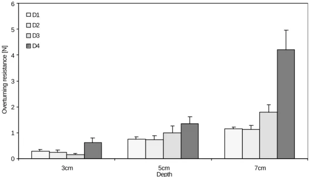
FIGURE 3.2 Overturning resistance of tap root models of four different sizes (D1=4.2 mm, D2=6.35mm, D3=8.50 mm, D4=12.70 mm) in three different depths (3 cm, 5 cm, and 7 cm) in sand ... 49
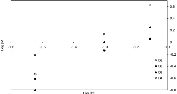
FIGURE 3.3 Log-Log dependency between the overturning moment (M) and the embedment depth (Df). ... 49
FIGURE 3.4 Log – Log dependency between the overturning moment (M) and the model diameter (D).. ... 50
FIGURE 3.5 Overturning resistance of tap root models of four different sizes (D1=4.2 mm, D2=6.35mm, D3=8.50 mm, D4=12.70 mm) in three different depths (3 cm, 5 cm, and 7 cm) in agricultural soil. ... 51
FIGURE 3.6 Log-Log dependency between the overturning moment (M) and the embedment depth (Df). ... 52 FIGURE 3.7 Log – Log dependency between the overturning moment (M) and the model diameter
(D). ... 52 FIGURE 3.8 The mechanism of anchorage failure under horizontal overturning force (Hu) in a)
cohesionless and b) cohesive media. ... 54 FIGURE 3.9 Two possible types of root failure under horizontal lateral loads (Hu).. ... 56 FIGURE 4.1 Pine seedlings planted in plastic containers (side and top view)... 62 FIGURE 4.2 Penetrometer resistance at four different soil depths (2.5 cm, 5 cm, 7.5 cm, and 10 cm)
for the three types of soil consistency (loose, semi-compact and, compact)... 64 FIGURE 4.3 Average maximum root axial length in both Pinus sylvestris and Pinus peuce seedlings
at the start and at the end of the experiment. ... 67 FIGURE 4.4 Average number of major lateral roots in Pinus sylvestris and Pinus peuce seedlings at
the start and at the end of the experiment... 68 FIGURE 4.5 Average axial root growth rate of a) Pinus sylvestris and b) Pinus peuce seedlings
grown at three different temperatures (15°C, 20°C, and 25°C) and in three different soil
consistencies (loose, semi-compact and, compact)... 69 FIGURE 4.6 Average increase in the number of major lateral roots in a) Pinus sylvestris and b)
Pinus peuce at three different temperatures (15°C, 20°C and, 25°C) in three different
consistencies (loose, semi-compact and, compact).. ... 71 FIGURE 4.7 Average diameter of major lateral roots in Pinus sylvestris and Pinus peuce at the start
and at the end of the experiment.. ... 72 FIGURE 5.1 Division of the space around the stem into quadrants.. ... 81 FIGURE 5.2 Top and side view of the planted seedlings and the flexing procedure. ... 82 FIGURE 5.3 Resistance to deflection in test and control P. sylvestris trees in three different
directions ... 87 FIGURE 6.1 a) Top view and b) side view of the winching apparatus and method used in this study. .. 98 FIGURE 6.2 Log-Log graph showing the relationship between the diameter at breast height (DBH)
of inner and outer trees and their maximum overturning moment (M). ... 104 FIGURE 6.3 Graph showing the relationship between the diameter at breast height (DBH) of inner
and outer trees in the stand and their root cross sectional area (CSA)... 105 FIGURE 6.4 Polar plot of the mean centres of the root cross sectional area of each tree.. ... 107 FIGURE 6.5 Graph showing the relationship between the asymmetry in the distribution of major
lateral root CSA (root asymmetry ratio) and the asymmetry in the overturning resistance
(anchorage asymmetry ratio) around the tree trunk. ... 108 FIGURE 6.6 Graph showing the relationship between the root cross sectional area (CSA) and the
soil shear strength in the three different soil horizons: 0-5cm, 5-10cm, and 10-15cm. ... 109 FIGURE 7.1 Regression lines between Log DBH and log M for the Pinus peuce trees from the inner
FIGURE 7.2 Regression lines between Log DBH and Log CSA for the Pinus peuce trees from the inner and outer belt of the stand in the Pelister National Park (MK).. ... 123 FIGURE 7.3 Average orientation of the centre of the root CSA (circular direction) plotted against
the magnitude of asymmetry (radial direction) for the Pinus peuce trees investigated. ... 124 FIGURE 7.4 Regression between root asymmetry ratio and the anchorage asymmetry ratio... 125 FIGURE 7.5 Penetrometer resistance of the soil in Pelister National Park [MK] compared to the one
in the Jodrell Bank Arboretum [UK]... 126 FIGURE 7.6 Average eccentricity in vertically eccentric lateral roots in Pinus peuce compared to the
one in Pinus sylvestris trees investigated in the Chapter Five of this thesis.. ... 131
LIST OF TABLES
TABLE 5.1. Differences in major lateral root CSA and in the number of major lateral roots in test and control trees in planes parallel and perpendicular to flexing, before and after the treatment... 89 TABLE 5.2. Average dry weight of the various constituents of investigated trees with the
average root:shoot ratio.. ... 89 TABLE 5.3. Average mechanical properties of stem and root wood in test and control trees... 90 TABLE 6.1 The mean anchorage rigidity and the percentage of the root cross sectional area
mobilised in tension during each pull of the overturning tests. ... 102 TABLE 7.1 Mean anchorage rigidity and distribution of the major lateral root CSA in four
different directions in the investigated Pinus peuce trees. ... 121
LIST OF PLATES
PLATE 2.1. Uprooting of real bulbs – the apparatus ... 26 PLATE 2.2. Development of bulb form in garlic and onion... 35 PLATE 4.1 The morphology and architecture of one-year-old a) P. peuce and b) P. sylvestris
root system... 66 PLATE 6.1 The root system of an average 18-year-old P. sylvestris tree from inside the tree
stand at the University of Manchester Granada Arboretum in Jodrell Bank, Cheshire ... 112 PLATE 7.1 Asymmetry in the distribution of major lateral roots around the trunk of P. peuce at
ABSTRACT
The research presented in this thesis investigated the functional morphology in root systems in relation to their role in providing anchorage and stability for the plant. The anchorage of different types of root systems was investigated as well as the influence of several environmental factors on their development. The research presented in this study was completed by carrying out a series of modelling, glasshouse and field experiments using physical models and real plants.
Model experiments showed that solid shapes like bulbs are very well suited to resist vertical upward forces, i.e. uprooting, and shed some light on the mechanism of anchorage in bulbs. The results of this laboratory study showed that the concept of optimal bulb shape for resisting uprooting is viable. Uprooting tests on real bulb plants confirmed the theoretical predictions about it, and showed the importance of bulbs in anchorage. This study also proved that the soil type is very important when considering the anchorage of solid forms such as the bulbs.
A second model study showed that the simplest models of tap root-dominated root systems increase their resistance to overturning with the third and second power of the embedment depth in cohesionless and in cohesive soil respectively. Anchorage strength of a root system dominated by a tap root will be maximised with minimum investment in structural material if the rigid tap root is extended to the largest possible depth.
Glasshouse experiments investigated the effects of soil compaction and temperature, two of the most important environmental factors, on the axial and lateral development and growth of the root systems of two species of young pines. It was shown that the rate of root axial development in both investigated species decreased with an increase in soil compaction whereas the lateral proliferation of their roots systems was not significantly affected by soil consistency. A temperature of around 15°C seemed to be optimal for the root elongation rate since the increase in axial length of the roots of both species was largest at this temperature.
The effect of mechanical stimulation as a factor in shaping the root systems of plants was also investigated. Apart from the changes caused to the parts of the tree above ground, unidirectional periodical flexing induced an increase in total root CSA and larger biomass allocation to the roots parallel to the plane of flexing which, in turn, resulted in a larger number of major lateral roots with larger CSA in the plane of flexing.
Mechanical and morphological field studies on two Pinus species investigated the anchorage of plate root systems and showed that lateral roots in older trees are not the major source of root anchorage in either of the species; although in both species a certain asymmetry in the distribution of major lateral root CSA was recorded, it was not significantly correlated to the asymmetry in anchorage.
DECLARATION
No portion of the work referred to in this thesis has been submitted in support of an application for another degree or qualification of this or any other institute of learning.
(1) Copyright in text of this thesis rests with the Author. Copies (by any process) either in full or of extracts, may be made only in accordance with instructions given by the Author and lodged in the John Rylands University Library of Manchester. Details may be obtained by the Librarian. This page must form part of any such copies made. Further copies (by any process) of copies made in accordance with such instructions may not be made without the permission (in writing) of the Author.
(2) The ownership of any intellectual property rights which may be described in this thesis is vested in the University of Manchester, subject to any prior agreement to the contrary, and may not be made available for use by third parties without the written permission of the University, which will prescribe the terms and conditions of any such agreement.
Further information on the conditions under which disclosures and exploitation may take place is available from the Head of Division of Integrative Biology, School of Biological Sciences.
THE AUTHOR
I obtained a BSc in Civil and Structural Engineering with Honours at the Faculty of Civil Engineering, Sts Cyril and Methodius University in Skopje, Macedonia, in July 1997. After a year of working as a geotechnical engineer in Skopje, Macedonia, in 1998 Open Society Institute granted me a scholarship to undertake MSc studies at the Central European University in Budapest, Hungary. I obtained a Master of Science in Environmental Sciences and policy in September 1999, and granted a scholarship jointly funded by The Foreign and Commonwealth Office, Open Society Institute, and the University of Manchester to undertake PhD studies at this University.
ACKNOWLEDGEMENTS
The work on the completion of this thesis was long and painstaking. I would like to express my eternal gratitude to my family: my mother Lidija, my brother Vladimir, and last but not least my dear Ricci, for their unconditional moral and material support, and the loads of positive energy that helped me to achieve this.
Of course, the outcome of the three-year work on this thesis would not have been so successful without the superb academic guidance of my supervisor, Dr A Roland Ennos whose approach to science is just marvellous.
I would also like to thank the people from the Open Society Institute both in Macedonia and at the Central European University in Budapest, who thought I was worth giving a chance as a future academic and awarded me a scholarship. I hope I would not disappoint them in the future.
I am deeply indebted to the staff and management of the institutions where I carried out my investigations: Thurston Heaton and David Newton from the University of Manchester Experimental Botanical Grounds; the staff from the University of Manchester Granada Arboretum at Jodrell Bank; the foresters from the Pelister National Park in Bitola, Macedonia; Dr Kole Vasilevski from the Faculty of Forestry and Dr Ljupco Dimitrievski from the Faculty of Civil Engineering, both at Sts Cyril and Methodius University in Skopje, Macedonia; Dr William ‘Bill’ Craig from the Civil Engineering Department, University of Manchester, and to Mr Zlatko Samardziev from REC Macedonia for the useful suggestions and contacts.
One big thanks to the ones that did not make me feel like a ‘stranger in a strange land’ – the lab people: Alison, Andy, Jo C, Jo W, Jannet, Jenny, Liz, Martin, Matt, Merewyn, Paul, Sofia, Sultan, Vasumathi, Vlad; and the ones that helped a lot and were not afraid to learn something about pulling trees: Dr. Olivera Pasanko, Kire Blazev and Aleksandar ‘Sandre’ Petrovski.
Dedicated to the loving memory of my first and best teacher – my father
CHAPTER ONE: INTRODUCTION
The force that through the green fuse drives the flower Drives my green age; that blasts the roots of trees Is my destroyer.
Dylan Thomas (1914-1953)
1.1 BACKGROUND
1.1.1 Types of Root Systems
The crucial role of root systems in plant stability and survival have started to receive much attention only in the last twenty years. One obvious discouragement previously to investigating the growth and function of root systems was their variable form and their extensive branching, which complicate experimentation, especially since roots are covered by soil.
In field conditions the root systems of plants are much more variable in form than their shoots. Considering their morphology, it is quite probable that the forces a plant must withstand could determine the shape of the root system. The simplest anchorage systems (Ennos 1989) are the ones designed to resist only axial uprooting forces, such as might be caused by grazing or weeding. Fibrous root systems , which are common in procumbent and climbing plants, have long roots that break, so that their tips do not contribute to anchorage, though they are optimal for weak soils. Short roots, in contrast, would be pulled out without mobilising their full strength (Ennos 1993). In these systems tension is transferred from the roots to the soil by the friction between them. However, it is worth noting that the influence of the solid shape of roots on their uprooting resistance has never been studied.
Mature self-supporting plants in contrast, have a range of root system types which must resist a more complicated set of forces, including overturning forces imposed by the wind. Such systems require at least one rigid element at the base of the stem to act as a lever (Ennos and Fitter 1992). Most woody plants, for example, have a rigid element in their anchorage system to resist rotation moments. Tap root systems resist rotation effectively, but longer and narrower taproots can easily break without mobilising the full soil resistance, whereas shorter ones can easily rotate without mobilising the full root strength.
Other root systems, like the heart root system, where horizontal and vertical lateral roots develop from the base of the tree (Köstler et al. 1968) are most common type of root system in angiosperms and are usually found in large trees. The plate root
systems , on the other hand, often found in gymnosperms, become more efficient at
large sizes, because the anchorage provided by the weight of the root-soil plate rises with the fourth power of the linear dimensions (compared to the third power for the tap roots) (Ennos 1993, Nicoll et al. 1995, Stokes et al. 1995). Major lateral roots play a decisive role in resisting lateral loads imposed on the tree. The chances of becoming a major root are greater for roots with a large diameter of primary xylem, or for roots with a special origin and position in the system that helps them to succeed in the battle for assimilates. In this manner it is expected (Coutts 1983a, Coutts et al. 1998) that trees with a suppressed crown (or trees with reduced assimilation) intensify the competition between roots and exaggerate the uneven pattern of root growth.
1.1.2 Factors Influencing Root System Form
The great variability in root form within species points to the strong influence of both genetic and environmental influences (Sutton 1969, Eshel and Waisel 1996). Root system form within species becomes increasingly variable with age as systems respond to a variety of stimuli, and only rarely are the numerous roots that constitute the root system exposed to uniform conditions. This variability has been referred to as evidence of the power of the environment to shape root system form (Sutton 1969). Trophic responses continue to influence the form of the developing root system throughout its growth and development. However, the competition for nutrients and the requirements for stability are intertwined in determining the optimal shape of the root system. It is possible that the most important factors influencing the plant’s ability to compete for nutrients are the relative size of the absorbing surface of its root system and the disposition of the root tips in relation to soil nutrients (Sutton 1969, Eshel and Waisel 1996). On the other hand, root system architecture alters in response to the mechanical stimuli the plant is receiving (Coutts 1983a, 1986), and is more influenced by the form of the basal roots.
Root system form can be much modified also by the soil environment, especially by a barrier of compact soil, or by other soil properties such as soil temperature, salinity, texture and structure. Soil compaction, which produces mechanical impedance that
might restrict root growth, arises from mainly externally applied forces such as trampling by animals or farm and tillage equipment. The effects of mechanical impedance on root growth have been reviewed extensively by Barley and Graecen (1967), Taylor et al. (1972), Graecen (1986), Bengough and Mullins (1990), and Bennie (1996). The influence of other soil properties on the root system form and development are reviewed by Brouwer and Hoagland (1964), Cooper (1973), Nielsen (1974), Glinski and Lipiec (1990), Bowen (1991), and McMichael and Burke (1996).
Although some thought has been put into the theory of the interactions of all of the root system types with soil (Coutts 1983b, Ennos 1993), the mechanics of anchorage of self-supporting plants has been studied mostly using an experimental approach. This line of investigation is in a sharp contrast with the theoretical framework used to investigate the resistance of plants to uprooting. The extreme complexity of mature anchorage systems is the source of most of the difficulties for modelling them, and several authors (Telewski 1995, Ennos 2000, Goodman and Ennos 2001) have promoted the need of modelling simpler, basic types of root systems as to lay down the base for more complex experimental research on this subject.
1.1.3 Root System Anchorage
Two situations (or their combination) are likely to occur in natural situations during plant’s growth: a) when a simple upward force is exerted on the plant (e.g. by a grazing animal) and b) when a lateral force is exerted on the stem (usually by wind). In reality, the first of these situations is most likely to happen to small, mostly non-woody plants with or without twisting movements accompanying the vertical force. For woody and tall herbaceous plants, lateral forces on the stem would be more important than vertical forces and would result in windthrow or often in stem failure. One of the two primary roles of root systems is to provide stability, preventing the wind from pushing the stem over (Coutts 1983b, Ennos 1991). However, unlike the other primary root functions of water and nutrient uptake and food storage, relatively little attention has been paid until recently to the mechanical role of roots in plant anchorage. This is surprising because lodging in agricultural crops, and windthrow in forestry result from anchorage failure of plants, and are a major source of economic loss to their growers (Coutts 1986, Stokes and Guitard 1997).
Whilst the anchorage of many smaller plants has been examined more recently (Ennos 1991, Goodman and Ennos 1998, 2001), the work of Coutts (1983b, 1986), on the mechanics of anchorage of Sitka spruce growing on peat in upland Britain, pioneered the work on how roots anchor trees. Almost all the earlier experimental work, although recognising the importance of the structural roots for anchorage, had not examined the way the roots actually anchor trees (e.g. Fraser 1962, Hintikka 1972, Somerville 1979). In his work Coutts outlined a range of techniques for identifying the ‘components of anchorage’, i.e. features of root systems that provide anchorage for the plant, and for quantifying their relative importance.
The more recent past has seen the emergence of theories of root anchorage mechanics based on the fundamentals of materials science and engineering pile foundation theory (Ennos 1993). These theories have largely been supported by experiments on a large variety of species of trees (Nicoll et al. 1995, Crook and Ennos 1996 and 1997, Brüchert
et al. 1997, Stokes et al. 1997b, Nicoll and Armstrong 1998) and herbaceous plants
(Ennos 1991, Crook and Ennos 1993, Gartner 1994, Goodman and Ennos 1998, 2001). They investigated the significance of such factors on root anchorage as: root radial and axial growth (Misra 1997, Dexter 1987 a,b); root system symmetry (Nicoll and Ray 1996, Coutts et al. 1998); and soil and environmental conditions (Stokes et al. 1997b, Goodman and Ennos 1999, Bingham 2001). However, most of the work on the anchorage of tree root systems has been done on only a limited number of species and there is a need for more information on the anchorage of as many species as possible (Ennos 2000) that are of commercial or environmental importance in forestry practice.
One of the objectives of this thesis is to try to reveal the relationship between the architectural characteristics and the anchorage efficiency of different types of root systems. In the long run, this will be helpful in understanding why different plants, from small herbs to trees, have such different anchorage systems, and how environmental factors such as soil type influence anchorage morphology and mechanics.
1.2 LINES OF INVESTIGATION
1.2.1 Modelling the Uprooting Resistance of Bulbs
The anchorage mechanics of bulbs has never been studied before despite the attempts made to explore the resistance of cylindrical roots to uprooting (Ennos 1989, 1990, Stokes et al. 1996, etc.). Acknowledging that uprooting is one of the most disastrous situations a plant might encounter during its life (either from a grazing animal or during gardening practice), it is important to find out the influence of different factors such as bulb geometry and embedment depth, as well as the type of soil in which it is embedded, on the uprooting resistance. In order to do this, in Chapter Two models of bulbs with different sizes and shapes were embedded at different depths in two different soil media. The mechanism of failure is described for each soil medium and an attempt is made to relate the uprooting resistance of the models to their geometry and the soil environment. The results are compared with the behaviour of real bulb plants grown in a glasshouse.
1.2.2 Overturning Resistance of Rigid Tap Roots
The vast majority of self-supporting plants are likely to be pushed sideways by a herbivore, or even more likely by the wind and either topple or lean permanently – a phenomenon known as ‘lodging’. To neutralise lateral loads these plants are expected to have at least one rigid element (Ennos 1993) that will resist with its bending resistance, while the surrounding soil resists with its compressive resistance. Engineers have formulated the theory of laterally loaded piles (Broms 1964 a,b) that might be used to explain the behaviour of tap root dominated systems. Chapter Three combines the engineering theory with practical biology by modelling different sizes of simple rigid tap roots, embedding them at different depths in different soil media, pulling them over, and recording the overturning moment. An attempt is made to relate the overturning resistance of model tap roots to their size, embedment depth and the soil medium in which they are embedded.
1.2.3 The Influence of Soil Compaction and Temperature on the Growth and Development of Root Systems in Two Pinus Species
Two of the major soil physical properties that influence root growth are its mechanical strength and temperature. Soil compaction, which results in mechanical impedance that might restrict root growth, arises from mainly externally applied forces such as trampling by animals or farm and tillage equipment, and as such it has been extensively reviewed in the past (Barley and Graecen 1967, Taylor et al. 1972, Russel 1977, Graecen 1986, Bengough and Mullins 1990, Glinski and Lipiec 1990, Bennie 1996). On the other hand, of all stresses associated with root initiation and development, temperature stress is most common; soil temperature changes can have significant effects on the growth and development of the root systems as discussed by Brouwer and Hoagland (1964), Cooper (1973), Nielsen (1974), Glinski and Lipiec (1990), Bowen (1991), and McMichael and Burke (1996). However, most of the studies investigating the effect of soil mechanical impedance, as well as the vast majority of the investigations of the effects of the temperature on root system growth and development have concentrated on crops or other fast growing plants. The influence of these factors on the axial elongation and lateral root initiation and development in the root systems of young Pinus sylvestris and Pinus peuce seedlings is investigated in Chapter Four of this thesis. The results of this study deepen the knowledge on two of the most important factors influencing root initiation and development in the early stages of growth, and add to the number of tree species investigated.
1.2.4 The Effect of Unidirectional Stem Flexing on Shoot and Root Morphology and Architecture in Young Pinus sylvestris Trees
Lateral loading of the plant stem can result either in root system failure (windthrow) or stem failure. Mechanical stresses experienced this way may cause alterations in both shoot and root growth, a process called thigmomorphogenesis (Jaffe 1973). Many of the previous studies on this subject have concentrated on shoot responses to lateral loads (Neel and Harris 1971; Jaffe 1973; Rees and Grace 1980, Telewski 1995), while root system responses to stresses caused by external loading have been investigated only in more recent years (Gartner 1994, Goodman and Ennos 1996, 1997, 1998, 2001; Stokes
et al. 1995, 1997b, Watson 2000), and even then only rarely in pine trees (Rees and
Grace 1980; Fredericksen et al. 1993, Downes et al. 1994, Valinger et al. 1994,; Telewski 1995, Lindstrom and Rune 1999, Moore 2000, Watson and Tombleson 2002).
Chapter Five presents the effect of unidirectional stem flexure of young Scots pines on their root system morphology and architecture, showing the extent to which the response to mechanical stimulation is localised in the root system, as well as the effect of the mechanical perturbation on the overall morphology of the tree. The changes in root system morphology and architecture as a consequence of the mechanical stimulation, are also compared with the similar changes in other, previously investigated species.
1.2.5 A Morphological and Mechanical Study of the Root Systems of Suppressed Crown Scots Pine Pinus sylvestris
Previous studies (Somerville 1979, Coutts 1983a, Nicoll et al. 1995, Coutts et al. 1998) have shown that root system asymmetry can greatly affect the stability of trees. Some aspects of root system symmetry, such as the origin and growth of primary roots (Coutts
et al. 1999) and their distribution around the tree trunk (Somerville 1979, Coutts 1983a)
have been investigated in the past. However, no investigation has been carried out on the possible connection between root system asymmetry, perhaps caused by environmental factors, and the stability of the tree. In Chapter Six a mechanical investigation of the stability and anchorage symmetry of suppressed crown Scots pine
Pinus sylvestris trees growing in clay soil were combined with a morphological
investigation of the lateral root system. The well-established winching method of Coutts (1983b, 1986) was used to investigate the resistance of the trees to lateral loads, which was then related to the distribution of the major lateral root cross-sectional area around the tree and with depth, as well as to the size of the tree trunk. An attempt was made to correlate the asymmetry in anchorage with the asymmetry in the root system as well as to define the major components of anchorage.
1.2.6 Anchorage Mechanics and Asymmetry in the Root System of Macedonian Pine Pinus peuce (Gris.)
Acknowledging that the overall stability of a tree might be significantly reduced by asymmetry in the root system (Coutts et al. 1999), Ennos (2000) suggested that a more advanced knowledge of the root morphology and architecture of more tree species might provide further insight into the way in which the form is related to the function in root systems. Using the methods for exploring the distribution and function of roots in the soil in connection to a tree’s anchorage used and described in Chapter Six of this
thesis, an investigation of the asymmetry of the overall root system in Macedonian pine
Pinus peuce was carried out. The vertical distribution of root biomass, especially in
relation to soil properties and competition for nutrients was also investigated. The results of this investigation are presented in Chapter Seven and these findings are compared to the ones for other previously investigated species, particularly to the related P. sylvestris which had grown in contrasting environmental conditions. This will help in gaining more knowledge on the factors that determine root development and root biomass distribution.
CHAPTER TWO: MODELLING THE UPROOTING RESISTANCE
OF BULBS: THE EFFECT OF SHAPE, SIZE, DEPTH, AND SOIL
TYPE
2.1 INTRODUCTION
The term ‘bulb’ is usually used to refer to the underground, fleshy storage structures of some herbaceous plants. However, only some of the plants commonly called ‘bulbs’ actually are bulbs. The simple definition of a bulb is ‘any plant organ consisting of a short stem bearing a number of swollen fleshy leaf bases or scale leaves, with or without a tunic, the whole enclosing the next year’s bud’ (Rees 1972). Onions, for example, have the features of a typical bulb together with their characteristic shape (Figure 2.1), having the largest diameter near the bottom and tapering to a point at the top, while nutrient uptake and/or contractile roots originate at a basal plate.
Figure 2.1 The features of a typical bulb. Developing leaves and flower buds are
protected by layers of leaf scales. Roots emerge from the basal plate.
Bulbs or bulb-like plants are usually perennials, having a period of growth and flowering, followed by a period of dormancy at the end of each growing season. During
the dormancy period they die back to ground level, losing their roots. The primary function of a bulb is to store energy and nutrient reserves to ensure the plant's survival. This bulbous habit therefore confers a measure of success to the plant, especially as a means of enduring extreme arid or cold seasons, or seasonal shade under a deciduous woodland canopy.
The main function of the contractile roots is to maintain the deep position of the bulb (Rees 1972, Pütz 1991, 1992a,b; 1996) where it is safe from potential herbivores and may also provide more effective anchorage for the plant, especially against uprooting. Of the few tests and observations which have been conducted on contractile roots, most have investigated how they cause downward movements of bulbs in the soil (Pütz 1991,1992a,b; 1993, 1996). The resistance of bulbs to downward movement has also been investigated by Pütz (1992b, 1996). However, the resistance of bulbs to upward movement (as a result of grazing or gardening activities, for example) has not been investigated, although it might occur as a result of grazing or of the traditional method of harvesting which involves pulling the bulbs out of the soil or undercutting them before their extraction (Rees 1972).
Our ignorance about bulbs is in sharp contrast to our knowledge about the resistance of cylindrical roots (Ennos 1989, 1990, Stokes et al. 1996, etc.) and root systems (Ennos 1991) to uprooting. This is even though, at least for some part of the year, bulbs lack roots and so must anchor themselves in the soil. Studies on roots have shown that root form and architecture are the dominant influence on the uprooting resistance of plants (Ennos 1993, Stokes et al. 1996, etc.); however, no proper investigation has been carried out on how the shape and size of bulbs influences their resistance to upward movement.
Fortunately, though botanists have failed to test the anchorage of bulbs, engineers have performed fairly similar tests on plate-like concrete or steel models (Balla 1961, Boone 1975) and have described the basic mechanics of the process. However, they have not specifically investigated the influence of model shape on the mechanical behaviour or the influence of model size on the overall resistance to upward movement through soil.
Therefore, it can be seen that the influence of the shapes and sizes of bulbs on the uprooting resistance has not been investigated, but intuitively they might be suspected
to have a big effect. In addition to this, increasing the depth of embedment might be expected to increase the resistance of the model to upward movement, both in cohesionless sand and in cohesive agricultural soil, in which completely different behaviour might be expected.
In this study, therefore, a series of tests were carried out to investigate the effect of shape, size, depth, and soil type on the uprooting resistance of model bulbs, to determine whether bulbs are optimally designed to prevent uprooting. In order to determine the extent to which these factors influence the uprooting resistance in real bulbs, a series of uprooting tests were also carried out on garlic and onion plants, with and without their roots.
2.2 MATERIALS AND METHODS
2.2.1 Models
The bulb models used in this experiment were made in several different shapes and sizes by packing different amounts of plasticine (Lewis’s non-toxic ‘Newplast’) on to a spruce ‘stem’ of cylindrical shape (4.5 mm in diameter, 30 cm long). They were later embedded in different soil media.
2.2.2 Soils
Two soil types were used in this investigation. The first soil was a dry, cohesionless, Mersey river sand. For the tests in this soil, the models were placed in steel cylindrical container of diameter 25.4 cm, and height 25.4 cm, on a thick layer of sand (cca. 10 cm) and more sand was poured over the models to the desired level, a process which ensured that it was loose and uncompacted. John Innes no.3 compost (Keith Singleton’s, Egremont, Cumbria) was selected as a second soil type, to represent a typical, albeit weak, agricultural soil. The models were placed in plastic tubes with a diameter of 12.5 cm, large enough to ensure that the sides did not interfere with the soil failure surface even for the largest models at the largest embedment depth. A layer of soil (cca. 4 cm) was first laid in the tubes, then the models were placed in the centre of the tube while loose soil was poured over the model to the desired level. The soil was then given
cohesion by saturating it with water, and draining it for one day in laboratory conditions (t=20ºC, 50% humidity), to gain a field capacity close to that of a natural agricultural soil.
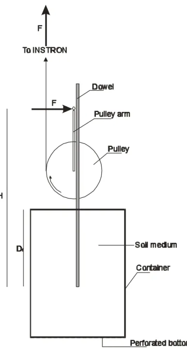
2.2.3 Mechanical Tests
Models’ stems were clamped to and were pulled out of soils using an INSTRON 4301 universal testing machine (Figure 2.2), with a 0.1 kN load cell, at a speed of 80 mm per minute. During the testing, a graph of force against absolute displacement was plotted by an interfacing computer, and used to measure the maximum pullout force. The pattern of surface failure was also observed.
Figure 2.2 The apparatus and method for uprooting model bulbs. The model is
embedded in a soil medium encased in a plastic tube, and clamped to the testing machine. The crosshead moves upwards with a constant speed and pulls the model out of the soil.
2.2.4 The Investigations
To investigate the phenomenon, a range of tests were carried out.
Preliminary tests: To investigate the effect of shape on uprooting resistance, six
different shaped models (cone, cylinder, bulb, sphere, inverted cone and inverted bulb) were made. Each of the models contained the same amount of material (25 g of
moving
crosshead
INSTRON
testing machine
model
perforated
bottom
soil
plasticine) and had the same maximum diameter of 3.3 cm, so that their heights ranged from 3.3 to 3.9 cm. Each was embedded in sand with their lowest surface at three different depths: 5 cm, 7 cm and 10 cm, and pulled out. Tests were repeated ten times for each model at each depth. The failure at the soil surface was observed during the uprooting process, noting down the diameter of disturbed soil. The maximum resistance was measured and plotted against the absolute displacement.
Main tests: The three shapes that showed the highest resistance to uprooting in the
preliminary tests were chosen for more detailed study, which involved additionally an investigation of the effects of size, depth and soil type on the uprooting resistance of the bulbs. These three shapes were modelled in three varieties each: with 12.5 g plasticine, producing models with diameter 2.4 cm; with 25 g plasticine for models with 3.3 cm diameter; and with 50 g plasticine for 4.2 cm diameter. Each size and shape of model was then tested by pulling it ten times out from three different depths: 5 cm, 7 cm and 10 cm both of sand and of agricultural soil. During the tests, the diameter of disturbed soil on the soil surface was noted. These observations justified the usage of the 12.5 cm diameter tubes.
The results were analysed using analysis of variance (ANOVA) to determine the importance of different factors in resistance of the models to uprooting.
Material tests on soils: To obtain the shear strength of both soil media, standard
engineering soil tests were carried out.
The material properties of Mersey river sand – the dry weight γ=26.5 kNm-3, the cohesion c=0.0 kNm-2, and the angle of internal friction ϕ=30º – were obtained from Boone (1975).
The shear strength of the agricultural soil was determined with a standard shear box test. A soil specimen was prepared in the same way as it was for the testing of models: fully saturated and then allowed to drain for a period of one day. This sample was laid in a shear box of dimensions 6 cm x 6 cm x 4 cm which was made of two parts. The upper part was pushed over the lower and the maximum force required to shear the specimen was measured and recorded with a Mecmesin portable force indicator PFI-200N.
To obtain the cohesion and the angle of internal friction of this soil type, this standard small shear box test (BS1377:Part7:1990:4, and ASTM D3080) was performed on a drained sample, a method introduced by Ennos (1989). A graph of shear stress vs. normal stress was plotted. The slope of the graph gave the angle of internal friction, while the intercept represented the cohesion of the sample. This method showed that this type of soil has dry weight of γ=16.5 kNm-3, cohesion c=0.38 kNm-2, and angle of internal friction ϕ=21º.
2.2.5 Anchorage Tests on Real Bulbs
Planting and growing of the bulbs. To investigate the influence of the size, shape and
embedment depth on the uprooting resistance in real bulbs, one garlic variety (Allium
sativum, Suttons seeds, UK), and one variety of pickling onion (Allium cepa, (Paris
Silverskin) Suttons seeds, UK) were planted and grown at the University of Manchester Experimental Grounds.
Garlic bulbs were grown from cloves planted in February 2002, in plastic pots (10 cm in diameter, 12.5 cm height) in John Innes no.3 compost (Egremont, Cumbria) and covered with black plastic foil until they germinated. A layer of soil was first laid in the pot, the clove was placed in the middle of the pot, and then covered with another layer of soil using light compaction.
Onion bulbs were grown from seeds, first being left in moist verniculite for ten days and then potted in small plastic pots (10 cm in diameter, 12.5 cm height) in John Innes no.3 compost (Egremont, Cumbria) in February, 2002. The planting was carried out in the same way as for the garlic.
Both onion and garlic were grown for 6 months in a glasshouse cubicle, in a controlled temperature environment of 15ºC to 23ºC, and were watered regularly. The pots were arranged in matrices 10 rows x 10 columns for both species, ensuring that all of the plants receive the same amount of light during the day.
Uprooting tests and measurements. The uprooting tests on both onion and garlic
plants started six weeks after their planting, when the root system was already formed and the formation of the bulb had already started. Before the test each plant was marked at the soil surface level with a permanent marker. In order to investigate the maximum
uprooting force required to uproot the bulb together with the intact roots, the plants were uprooted with an apparatus consisting of a cork padded clipper which gripped the plant stalk at one end, and at the other end connected to a portable force meter (MECMESIN PFI-200N) (Plate 2.1). The apparatus together with the clipped plant stalk was manually moved upwards at a rate of cca. 0.5 cm per second until the whole bulb together with the root system was out of the soil. The maximum uprooting force required to uproot the bulb out was measured and displayed on the portable force meter.
Plate 2.1 Uprooting of real bulbs – the apparatus. An apparatus consisting of a
portable force meter connected to a cork padded clipper that grips the plant stalk is used to uproot the bulb by manually moving it upwards at a rate of 0.5 cm per second.
The remains of the soil were then washed away from the bulbs, and the maximum diameter of the bulb measured with callipers. The embedment depth was measured with a ruler from the root plate to the point on the stem which marked the soil surface level.
To investigate how much of the uprooting resistance was contributed by the bulb alone, the root system was then carefully cut off at the basal plate with scissors, and the plant was replanted at the same embedment depth into the same pot, with the soil prepared in the same way as it was when originally planted. The soil was watered to saturation, and left to drain for 24 hours to achieve water content close to the field potential. The plants were then uprooted again with the same apparatus, at a same rate of manual vertical movement.
To investigate the importance of the bulb for uprooting resistance, the percentage
contribution of the bulb to the overall uprooting resistance of the plant was calculated
by dividing the maximum uprooting force of the bulb without roots by the maximum uprooting force of the intact plant.
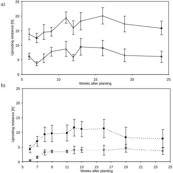
To monitor the changes in the uprooting resistance of the bulbs throughout the growing season the uprooting tests were carried out 6, 8, 9, 11, 12, 13, 14, 16, 19, and 24 weeks after planting.
2.3 RESULTS
2.3.1 Preliminary Tests
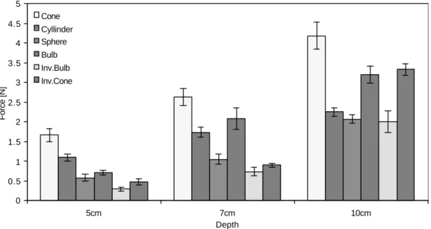
During the preliminary testing, on initial upward movement of the model a sand surface of diameter 0.75 times the model diameters was disturbed around the stem. Fairly small soil bodies were noticed on the upper side of the models as they emerged from the sand. The force rose to a maximum at displacements of approximately 3 to 3.5% of the depth. The maximum uprooting resistance of the different models is shown on Figure 2.3 The mean force varied from 0.293 N for the inverted bulb shape at 5 cm, to 4.19 N for the cone at 10 cm depth.
Figure 2.3 The uprooting resistance of six different shapes of bulb models. Results
are for cone, cylinder, sphere, bulb, inverted cone and inverted cylinder shapes with maximum diameter d=3.3cm, embedded at three different depths (5 cm, 7 cm and, 10 cm) in sand. Error bars indicate ± SE.
Two-way ANOVA of the results showed that both model shape and depth had a significant effect (p<0.001) on the uprooting resistance. The cone was most resistant to uprooting followed by the bulb, the cylinder, the sphere, the inverted cone and the inverted bulb. On average, the best shape was the cone, which resisted on average a 20.5% greater force than the bulb, 23.5% better than the cylinder, 106.4% better than the inverted cone, 112.3% better than the sphere, and 136.4% better than inverted bulb. The three shapes that performed best: the cone, the bulb and the cylinder, were therefore chosen for further studies. Resistance also rose with depth (p<0.001), models at 5 cm on average having an uprooting resistance 61.2% of those at 10 cm.
There was a significant (p<0.001) interaction between the two factors: model shape and depth. The resistance of the different models increased by different amounts when the embedment depth increased. Inverted cone models showed the greatest increase in uprooting resistance with depth, and cylindrical ones the least.
2.3.2 Main Tests
Models in sand: The behaviour during the uprooting tests on the cone, bulb and
cylinder was similar to that seen in the preliminary tests; the sand failed in shear near
0 0.5 1 1.5 2 2.5 3 3.5 4 4.5 5 5cm 7cm 10cm Depth Force [N] Cone Cyllinder Sphere Bulb Inv.Bulb Inv.Cone
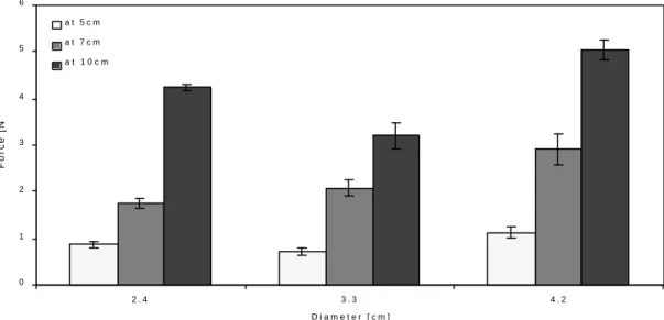
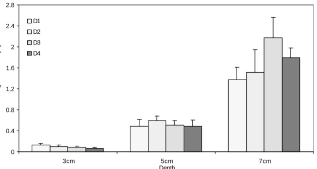
the upper surface of the model, allowing only a small soil body to form above the model. The failure of the sand was local and disturbed an area of diameter approximately 0.75 times the largest model diameter around the stem, on the surface of the soil medium before emerging on the surface. The maximum uprooting forces measured in these models ranged from 0.713 N for a bulb of 2.4 cm diameter at 5 cm depth to 4.242 N for a bulb of 4.2 cm diameter at 10 cm depth. Results are shown for the bulb shaped models in Figure 2.4.
Three-way ANOVA showed that shape, size and depth all significantly (F1,269=30.602,
p<0.001) affected the uprooting resistance of bulbs in sand. Just as in the preliminary tests, it was found that cone shaped models were the best, performing on average 20.5% better than bulbs, and 23.5% better than cylinders.
The size of the model was also a significant factor (F1,269=29.467, p<0.001) in resisting
uprooting, but the effect was not great. The resistance of the models actually decreased with their size before going up again. Bulb shaped models are an example of this trend (Figure 2.4). The resisting force decreased on average by 10.5% when increasing the maximum diameter from 2.4 cm to 3.3 cm, but went up on average by 33.3% in the 4.2 cm diameter models. Overall, regression of LogF vs. LogD for each shape at each depth showed that resisting force is less than proportional to the largest diameter of the bulb. The slope varied from 0.212 to 0.658 and in five out of nine cases the slope was significantly (p<0.05) less than one.
Figure 2.4 Uprooting resistance of bulb shaped models with three different diameters (2.4 cm, 3.3 cm and, 4.2 cm) at three different depths (5 cm, 7 cm and, 10 cm) in sand. The uprooting resistance of the model bulbs increased with the depth and
with the increase in model diameter (except for the models with d=3.3 cm at 10 cm depth). Error bars indicate ± SE.
The resistance increased significantly (F1,269=628.198, p<0.001) faster with the
embedment depth Df (Figure 2.4). In particular the smallest bulbs proved to be far more
efficient at larger embedment depths, resisting more than four times higher forces at 10 cm than at 5 cm depth. LogF vs. LogDf regression for each shape and each size of
model, however, showed that the slope of these curves ranged from 1.209 to 2.444, in four out of nine models the slope was significantly (p<0.05)greater than one, and in six out of nine models the slope was significantly (p<0.05) less than 2.
There were also significant interactions between the factors (p<0.001). The uprooting force increased significantly (F1,269=22.465, p<0.001) more with diameter for the
cylinders than the other shapes. The uprooting force also increased significantly (F1,269=8.177, p<0.001) more with embedment depth for the bulb-shaped models than
for the cylindrical ones, so the slope of the LogF vs. LogDf curve for bulb-shaped
models is steeper than for the cylinders
Models in agricultural soil: A different pattern of soil failure was observed in
agricultural soil from that seen in sand. Soil failed in shear around the model, but cohesion allowed the formation of a large soil body above the model. The failure surface of this soil body was curved and disturbed the soil on the surface to a diameter that was 2 to 2.5 times the largest diameter of the model, complying with the theory of
0 1 2 3 4 5 6 2 . 4 3 . 3 4 . 2 D i a m e t e r [ c m ] Force [N] a t 5 c m a t 7 c m a t 1 0 c m
resistance of shallow foundations under tension, best described in Balla (1961). This fact justified the use of the 12.5 cm diameter plastic tubes, which ensured that there was no interference between soil failure body and the walls of the tube. The smaller diameter models showed a maximum force at higher absolute extensions (3 to 5 mm, compared to 2 to 3 mm for the larger diameters) at every depth, particularly at 10 cm depth. This is probably because there were different types of breakage mechanisms: larger models broke the soil in a curved surface, while the smaller ones broke it locally in the vicinity of the model itself. A negative water pressure was observed after the pullout of the models in agricultural soil, since a certain amount of water drained through the perforated bottom of the tube.
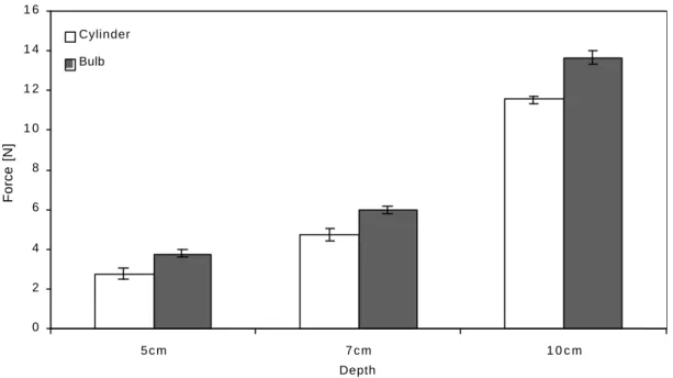
The resisting forces measured for the models in agricultural soil ranged from 2.765 N for the 2.4 cm diameter cylinder at 5 cm depth, to 13.664 N for the 4.2 cm diameter cone at 10 cm depth, which is approximately three times higher than the resistance in the sand. Three-way ANOVA also showed significant (p<0.001) effects of all three factors (shape with F1,269=91,756, size with F1,269=170.004, and depth with
F1,269=337.285) just as in the sand.
There were similar differences between the shapes as in the sand. Conical models performed on average 20% better than bulbs, and 29% better than cylinders at all depths. Typical example of that difference is shown for the cylindrical and the bulb-shaped models of 2.4 cm diameter on Figure 2.5.
Figure 2.5 A comparison between uprooting resistance of the cylinder and bulb shaped models. The results are for models with maximum diameter d=2.4 cm,
embedded at three different depths (5 cm, 7 cm and, 10 cm) in agricultural soil. The uprooting resistance of the models increased both with depth and with the increase in model diameter, but the bulb shaped model always resisted better than the cylinder shaped one. Error bars indicate ± SE.
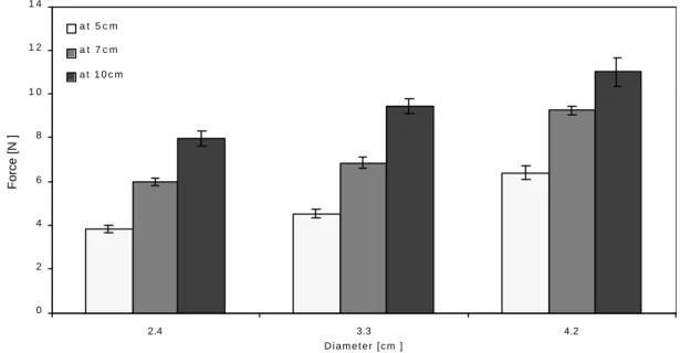
Measurements on the models with same shape but with different diameters also showed a greater effect of diameter. The resistance increased by 27.8% on average, when increasing the diameter from 2.4 cm to 3.3 cm, and by an additional 34.3% when increasing the diameter from 3.3 cm to 4.2 cm. Slopes of the regression line of LogF vs. LogD were not significantly (p>0.05) different from 1 for the three shapes at all three depths in agricultural soil, the slopes of these curves ranging from 0.761 for cone shaped models, to 1.054 for bulb shaped ones. This suggests that the maximum resistance is directly proportional to the diameter of the model.
Increasing the embedment depth increased the uprooting force significantly (F1,269=337.285, p<0.001), but less than in sand. The bulb-shaped models showed a
typical increase of the uprooting resistance with the depth, and these results are shown on Figure 2.6. The slopes of regression lines of LogF vs. LogDf showed slopes ranging
from 0.969 (bulb shape) to 1.070 (cylinder) for the models in agricultural soil. None of the slopes of the nine different models were significantly different from 1, showing that uprooting resistance is directly proportional to the embedment depth.
0 2 4 6 8 1 0 1 2 1 4 1 6 5 c m 7 c m 1 0 c m Depth Force [N] Cylinder Bulb
Figure 2.6 Uprooting resistance of bulb shaped models with three different diameters (2.4 cm, 3.3 cm and, 4.2 cm) at three different depths (5 cm, 7 cm and, 10 cm) in agricultural soil. The uprooting resistance increased approximately
proportionally with the embedment depth. Error bars indicate ± SE.
Again, there were significant (p<0.001) interactions between the factors. As in sand, the uprooting force increased significantly (F1,269=3.124, p=0.016) with the diameter for
the cylindrical models than for the other shapes, but unlike then, this time even more with the depth (F1,269=5.881, p<0.001).
2.3.3 Anchorage Tests on Real Bulbs
Uprooting tests on real bulb plants worked well and produced results comparable to the ones from the model experiments. The resisting force of both the intact plants and bulbs to uprooting in both species rose to its maximum during uprooting at absolute extensions ranging form 3 to 10 mm before falling down again, in a similar fashion as in the model investigations.
The shape of the bulbs changed throughout the experiment. Plate 2.2 (a, b) shows that the underground part of the garlic seedlings was cylindrical in shape, resembling our cylindrical models for the first 9 weeks after planting, but they then started to lay down more material near the root plate, so they resembled our conical shaped models. The average maximum bulb diameter increased from 1.58±0.11 cm six weeks after planting, to 2.35±0.23 cm 24 weeks after planting.
0 2 4 6 8 1 0 1 2 1 4 2.4 3.3 4.2 D i a m e t e r [ c m ] Force [N ] a t 5 c m a t 7 c m a t 1 0 c m
Onion bulbs also kept an approximately cylindrical shape until 11 weeks after planting when the material started to be laid down more near the root plate and they started to resemble our bulb shaped models (Plate 2.2 c, d). The average maximum bulb diameter increased from 0.63±0.08 cm six weeks after the planting, to 4.84±1.43 cm 24 weeks after the planting.
a) b)
c) d)
Plate 2.2 Development of bulb form in garlic (a, b) and onion (c, d). a) Six-week-old
garlic with cylindrical shape of its underground part; b) 19-week-old garlic with already formed bulb with conical shape; c) 8-week-old onion with cylindrical shape of its underground part; d) 19-week-old onion with bulbous shape of its underground part.
Figure 2.7a shows that the average maximum uprooting resistance of the intact garlic plants, increased from the start of the experiment and reached its maximum 16 weeks after the planting before decreasing again until the end of the experiment. The uprooting resistance of the bulb without roots also followed this trend, reaching its maximum 13 weeks after planting, before dropping towards the end of the experiment.
a)
b)
Figure 2.7 Average maximum uprooting resistance in a) garlic and b) onion. The
experiments started six weeks after the planting when the bulbs started to form and it lasted until 24 weeks after the planting. Every point in the graph represents a mean value of ten samples. Solid symbols for intact plants, empty symbols for plants without roots. Error bars indicate ± SD.
The average maximum uprooting resistance of the intact onion plants (Figure 2.7b) showed similar pattern; after the initial increase, it reached its maximum 13 weeks after the planting, before falling again until the end of the experiment. In sharp contrast with the garlic, the uprooting resistance of the bulb without roots did not follow this trend,
0 5 10 15 20 25 5 10 15 20 25
Weeks after planting
Uprooting reistance [N] 0 5 10 15 20 25 5 7 9 11 13 15 17 19 21 23 25 Weeks after planting
showing a constant increase throughout the duration of the experiment, though it did level off towards the end.
Throughout the experiment the average embedment depth of garlic did not change significantly: from 5.43±0.09 cm six weeks after planting to 4.74±0.07 cm 24 weeks after planting. However, the embedment depth of the onion increased from 1.35±0.08 cm six weeks after the planting to 2.90±0.09 cm 24 weeks after planting.
The relative contribution of the bulb to the overall uprooting resistance in garlic showed no pattern over time ranging between 29.02±2.99 % seven weeks after planting, to 53.52±4.32 %, nine weeks after planting. In contrast, the relative contribution of the bulb in onion plants increased throughout the experiment, from 15.55±1.89 % six weeks after planting to 37.59±3.02 % at the end of the experiment.
2.4 DISCUSSION
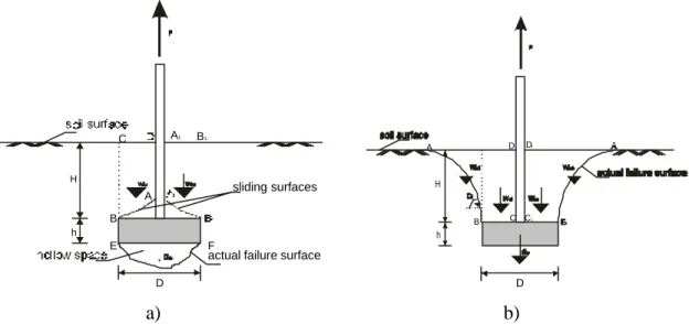
The testing procedure described above worked well, and has shown the relative importance of factors like shape, depth of embedment, and size in the uprooting resistance of the bulbs; cones resist uprooting most strongly, followed by bulb shapes, while depth has a stronger influence in sands than in agricultural soils, and diameter a stronger influence in agricultural soils. These results can be explained in engineering terms, as they are typical of the behaviour of shallow foundations.
In cohesionless soils the soil failure mechanism due to uprooting forces suggests that the shear resistance of the soil is the most important factor in the absence of cohesion. When an uprooting force is applied, the soil above the model slides along the shearing surfaces (Figure 2.8 a) and small soil failure bodies are formed. Most of the force is required to cause local shear failure. The weight of these failure bodies only slightly increases the uprooting resistance of the model in this soil medium.
a) b)
Figure 2.8 Patterns of soil failure in a) sand and b) agricultural soil. When the
uprooting force F acts on the model, the soil above the model (ABCD and A1B1C1D1)
forms a, so called, ‘soil failure body’. This soil fails in shear along the outside surfaces allowing the model to move upwards. Wi - the weight of a certain soil segment, D - the
model diameter, h – the model height, H+h - the embedment depth.
In cohesive agricultural soils and clays, on the other hand, the uprooting force causes shearing of the soil above the model along a curved shearing surface (Figure 2.8 b). The soil cohesion allows the formation of a soil failure body confined within this surface – an amount of soil far larger than the one in sand. According to Balla (1961), the ultimate pullout resistance of a model in cohesive soil is the sum of the self weight of the soil, plus the side sliding resistance of the failure surface (Figure 2.8 b); these both depend on the geometry of the model and the physical/mechanical properties of the soil. The shearing resistance of the soil contributes only slightly towards the uprooting resistance of the model.
The implications of these results and the theory behind them on the design of bulbs are evident. First and foremost, these results suggest that to maximise anchorage bulbs should be conical. The depth and size of the bulb also both have a significant effect but to different extents in the two different media. Increasing depth has a greater effect in sand, while increasing diameter has a greater effect in the agricultural soil.
Conical bulbs, however, are not common in nature. This may be because sharp edges are not favoured by nature because of possible high-stress concentrations in them, which could lead to breakage even under small loads. Bulb shapes which closely resemble a cone, do show stronger resistance to uprooting than the spheres.
H h D A B C D C1 D1 H h D A B C E F
actual failure surface sliding surfaces
Furthermore, an optimal bulb shape should also enable relatively easy downward movement by the use of contractile roots, because the downward movement of bulbs (Pütz 1992a,b; 1993, 1996) strongly affects the enhancement of the bulb anchorage and its uprooting resistance.
In order to have larger soil failure bodies in cohesionless soils, it is necessary to have the model embedded at a larger depth to ensure greater soil shear strength, and to a lesser extent to have larger model diameters in order to mobilise as large a shear surface as possible. This combination suggests that the conical shaped bulbs would be the best to resist uprooting in cohesionless soils because the basal part of the bulb would be the widest and would have the largest surface area. It is also conceivable that a wider angle at the top of the bulb would allow more efficient formation of a small soil failure body that, with its weight, will also contribute towards greater uprooting resistance, together with the shear resistance of the sand. However, because the size of the model has less effect it might therefore be expected that the bulbs in cohesionless soil should split into lots of smaller bulbs with a larger total surface area that would resist uprooting better.
A bulb designed by these criteria partially coincides with the form of the real bulbs in this study, as well with the recorded forms of bulbs embedded at different depths (Pütz 1996). For example, rounder bulbs tend to be found immediately beneath the soil surface and more elongated ones at greater depths. Smaller and broader bulbs with a large surface area would be favoured in sandy soil, because that should be expected to enhance the shear resistance of the sand that fails only locally around the bulb. Furthermore, bulbs in sandy soil might be expected to be found at larger depths because the shear resistance of the sand increases with the depth where it is expected to be more compact.
Considering bulbs in agricultural soil, it is clear that the cohesion of this type of soil acts to greatly increase uprooting resistance. The maximum diameters of the bulbs should be located at deeper levels to enable formation of as large a soil failure body as possible that will, with its weight and greater surface area and hence friction, contribute largely to the resistance of upward forces. In this respect, the poor performance of the cylindrical models in clay was probably due to its shallower mobilised soil body; the cylinder activates a smaller amount of soil in the friction cylinder above the largest diameter of the model. The cone and the bulb activate almost the same amount of soil,