HAL Id: insu-01869118
https://hal-insu.archives-ouvertes.fr/insu-01869118
Submitted on 17 Sep 2018
HAL is a multi-disciplinary open access
archive for the deposit and dissemination of
sci-entific research documents, whether they are
pub-lished or not. The documents may come from
teaching and research institutions in France or
abroad, or from public or private research centers.
L’archive ouverte pluridisciplinaire HAL, est
destinée au dépôt et à la diffusion de documents
scientifiques de niveau recherche, publiés ou non,
émanant des établissements d’enseignement et de
recherche français ou étrangers, des laboratoires
publics ou privés.
Facies architecture of Miocene subaqueous clinoforms of
the New Jersey passive margin: Results from
IODP-ICDP Expedition 313
Jean-Noël Proust, Hugo Pouderoux, Hisao Ando, Stephen Hesselbo, David
Hodgson, Johanna Lofi, Marina Rabineau, Peter Sugarman
To cite this version:
Jean-Noël Proust, Hugo Pouderoux, Hisao Ando, Stephen Hesselbo, David Hodgson, et al..
Fa-cies architecture of Miocene subaqueous clinoforms of the New Jersey passive margin: Results from
IODP-ICDP Expedition 313. Geosphere, Geological Society of America, 2018, 14 (4), pp.1564-1591.
�10.1130/GES01545.1�. �insu-01869118�
Facies architecture of Miocene subaqueous clinothems of the New
Jersey passive margin: Results from IODP-ICDP Expedition 313
Jean-Noël Proust
1,*, Hugo Pouderoux
1,*, Hisao Ando
2,*, Stephen P. Hesselbo
3,*, David M. Hodgson
4,*, Johanna Lofi
5,*, Marina Rabineau
6,*, and
Peter J. Sugarman
7,*
1Geosciences, CNRS, University of Rennes, Rennes 35042, France
2Department of Earth Science, College of Science, Ibaraki University, Bunkyo Mito 310-8512, Japan 3Camborne School of Mines, University of Exeter, Penryn Campus, Penryn, Cornwall TR10 9FE, UK 4School of Earth and Environment, University of Leeds, Leeds LS2 9JT, UK
5Géosciences, CNRS, University of Montpellier, Montpellier 34090, France
6Géosciences Océan, CNRS, Institut Universitaire Européen de La Mer, Plouzané 29280, France 7New Jersey Geological Survey, Trenton, New Jersey 08638, USA
ABSTRACT
Understanding the history, causes, and impact of sea-level changes is a challenge for our societies that face accelerated global sea-level rise. In this context, improvement of our knowledge of sea-level changes and shoreline migration at geological time scales is critical. The preserved, laterally correla-tive sedimentary record of continental erosion on passive margins has been used to reconstruct past sea level. However, the detailed nature of a basic clinothem progradational pattern observed on many of these margins is still poorly known. This paper describes the sedimentary facies and interprets the depositional environments and the architecture of the clinothems of the New Jersey shelf (offshore northeastern USA) to depict the origin and controls of the distribution of the sediment on the margin. We analyze 612 cores totaling 1311 m in length collected at three sites 60 km offshore Atlantic City, New Jer-sey, during International Ocean Discovery Program–International Continental Scientific Drilling Program (IODP-ICDP) Expedition 313. The three sites sam-pled the lower to middle Miocene passive margin sediments of the New Jer-sey shelf clinothems. We also collected wireline logs at the three sites and tied the sedimentary architecture to the geometry observed on seismic profiles. The observed sediment distribution in the clinoform complex differs from that of current models based on seismic data, which predict a progressive increase in mud and decrease in sand contents in a seaward direction. In contrast, we observe that the clinoforms are largely composed of muds, with sands and coarser material concentrated at the rollover, the bottomset, and the toe of the slope. The shelf clinothem topsets are storm-influenced mud whereas the foreset slope is composed of a mud wedge largely dominated by density cur-rent deposits (e.g., low-density turbidites and debrites). The architecture of the clinothem complex includes a composite stack of ~30-m-thick clinothem
units each made up of four systems tracts (Transgressive, Highstand, Forced-Regres sive, and Lowstand Systems Tract) building individual transgressive-regres sive sequences. The presence of mud-rich facies deposited during high-stands on the topset of the clinoform, 40–60 km offshore from the sand-prone shoreface deposit (observed in the New Jersey onshore delta plain), and the lack of subaerial erosion (and continental depositional environments) point to a depositional model involving a subaerial delta (onshore) feeding a dis-tant subaqueous delta. During forced regressions, shelf-edge deltas periodi-cally overstep the stacks of flood-influenced, offshore-marine mud wedges of the New Jersey subaqueous delta, bringing sand to the rollover and building up the large-scale shelf-prism clinothems. The clinothem complex develops on a gently dipping platform with a ramp-like morphology (apparent dip of 0.75°–0.5°) below mean storm wave base, in 30–50 m of water depth, 40– 60 km seaward of the coastal area. Its shape depends on the balance between accom mo da tion and sedimentation rates. Subaqueous deltas show higher ac-cumulation rates than their subaerial counterparts and prograde three times further and faster than their contemporaneous shoreline. The increase in the intensity of waves (height and recurrence intervals) favors the separation be-tween subaqueous and subaerial deltas, and as a consequence, the formation of a flat topset geometry, a decrease in flood events and fluvial discharge, an overall progressive decrease in sediment grain size (from sequence m5.45, ca. 17.8–17.7 Ma, onwards), as well as an increase in sedimentation rates on the foresets of the clinoforms. All of these are recognized as preliminary signals that might characterize the entry into the Neogene icehouse world.
INTRODUCTION
Passive margin successions are commonly characterized as relatively sim-ple suites of sedimentary strata truncated by unconformities that can be cor-related regionally, and in some cases worldwide. They show a gradational evo-lution of depositional environments from continental to deep marine realms,
GEOSPHERE
GEOSPHERE; v. 14, no. 4
https://doi.org/10.1130/GES01545.1
9 figures; 1 table; 1 set of supplemental files
CORRESPONDENCE: jean -noel .proust@ univ -rennes1.fr
CITATION: Proust, J.-N., Pouderoux, H., Ando, H., Hesselbo, S.P., Hodgson, D.M., Lofi, J., Rabineau, M., and Sugarman, P.J., 2018, Facies architecture of Miocene subaqueous clinothems of the New Jersey passive margin: Results from IODP-ICDP Expedition 313: Geosphere, v. 14, no. 4, p. 1564–1591, https:// doi .org /10 .1130 /GES01545.1.
Science Editor: Shanaka de Silva Guest Associate Editor: David Burns McInroy
Received 14 April 2017
Revision received 28 December 2017 Accepted 2 May 2018
Published online 14 June 2018
OPEN ACCESS
GOLD
This paper is published under the terms of the CC-BY-NC license.
© 2018 The Authors
*E-mail: jean -noel .proust@ univ -rennes1 .fr; hugo .pouderoux@ univ -rennes1 .fr; hisao .ando .sci@ vc .ibaraki .ac .jp; s.p.hesselbo@ exeter .ac .uk; d.hodgson@ leeds .ac .uk; johanna .lofi@ gm .univ -montp2 .fr; marina .rabineau@ univ -brest .fr; Pete .Sugarman@ dep .state .nj.us
Research Paper
1565
Proust et al. | New Jersey Miocene subaqueous clinothemsGEOSPHERE| Volume 14 | Number 4
including the shoreline, and a well-known subsidence history. As such, pas-sive margins have for a long time been used to reconstruct global sea-level variations on geological time scales (e.g., Vail et al., 1977; Miller et al., 2005). Sequence stratigraphy proved to be an effective tool to decipher the passive margin sedimentary record from the earliest outcomes of seismic stratigraphy (Vail et al., 1977; Posamentier et al., 1988) to the most recent standardization (e.g., Catuneanu et al., 2009), applications (e.g., Embry, 2009), and simplifica-tions (Neal and Abreu, 2009; Miller et al., 2018). Numerous hypotheses, how-ever, have not been fully tested yet, e.g., the nature of the sedimentary facies that compose the prograding clinothems on the shelf—a classic end mem-ber of most passive margin sedimentary records (e.g., Mitchum et al., 1977; Berg, 1982; Alexander et al., 1991; Pirmez et al., 1998; Hubbard et al., 2010, Helland-Hansen et al., 2012). Similarly, the timing and phase relationship of these sedimentary facies with respect to relative sea-level changes (Reynolds et al., 1991) or the paleo–water depth of sediment deposited at the top and the toe of the clinoforms (Greenlee and Moore, 1988) have not been determined definitively. Clinoforms are distinct sigmoidal geometric features associated with topset, foreset, and bottomset deposits that generally prograde seaward (termed a clinothem). Clinothem topsets were originally termed as the shelf and the rollover point at the shelf break (Vail et al., 1977). This has created confusion because the modern continental shelf-slope break is typically in 120–200 m of water (e.g., Heezen et al., 1959), and it has been shown that the rollover features (also called “depositional shelf breaks”) associated with clino-thems are shallower, showing different features than the shelf-slope break.
This paper seeks to ground-truth the vertical succession and lateral facies associations of clinothems in the relatively simple passive margin system of the New Jersey shelf (offshore northeastern USA) by using the data provided by International Ocean Discovery Project–International Continental Scientific Drilling Program (IODP-ICDP) Expedition 313 (Mountain et al., 2010a, 2010b). We examine successively the sedimentary facies found in the coreholes, and the seismic and sedimentary architecture of the clinothems; we propose a stratigraphic and depositional model for the New Jersey clinothems that com-bines subaerial-subaqueous delta with shelf prism–scale clinoforms and dis-cuss some important factors controlling this complex architecture.
BACKGROUND WORK
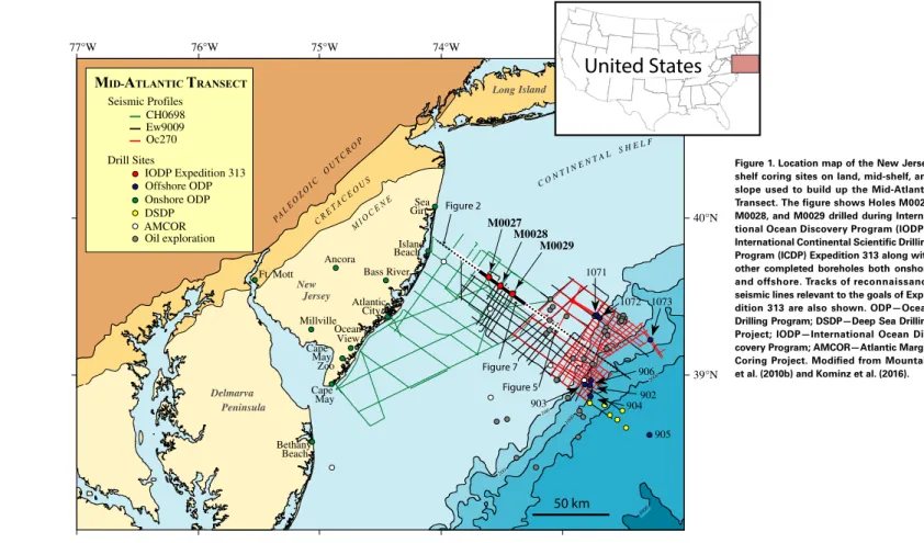
The New Jersey shelf is part of the U.S. mid-Atlantic margin that extends from New Jersey through Delaware to Maryland (Fig. 1). The U.S. Atlan-tic margin is a classic passive margin, which showed a rifting phase in the Late Triassic (ca. 230–198 Ma; Sheridan and Grow, 1988; Withjack et al., 1998) and seafloor spreading commencing during the Early to Middle Jurassic (180–165 Ma), followed by thermal subsidence, sediment loading, and flexure (Watts and Steckler, 1979; Reynolds et al., 1991). The sedimentary succession consists of Upper Triassic alluvial, evaporitic, and restricted marine sediments injected by dikes, sills, and lava flows, overlain by a thick (8–12 km) Jurassic to
mid-Cretaceous limestone and shale succession fringed by a barrier reef com-plex (Poag, 1985a). Sedimentation rates decreased from the Late Cretaceous to the Paleogene, building up a mixed siliciclastic carbonate ramp ending in a condensed and starved clay-rich carbonate ramp with the general cooling of temperatures, by the late middle Eocene (onshore) to earliest Oligocene (offshore) (Miller and Snyder, 1997; Steckler et al., 1999). Due to the increase of tectonically and/or climatically driven denudation in the hinterland (Poag and Sevon, 1989; Poag, 1992; Poag and Ward, 1993), sediment supply increased in the late Oligocene and Miocene, building out progressively a large set of prograding clinothems (Fulthorpe and Austin, 1998) that were capped by Pleis-tocene deposits (Davies et al., 1992; Austin et al., 1995, 1996).
The New Jersey shelf prograding clinothems were first recognized with (low-resolution) multi-channel seismic profiles collected by Grow et al. (1979) and Schlee (1981) to image rift-stage sediments. Later studies outlined Paleo-gene and NeoPaleo-gene sequences (e.g., Poag and Schlee, 1984; Poag, 1985b; Poag and Ward, 1987; Greenlee and Moore, 1988) and, by using higher-resolution seismic data (from cruise Ew9009 [http:// www -udc .ig .utexas .edu /sdc /cruise .php ?cruiseIn =ew9009] on the R/V Ewing in 1990, cruise Oc270 [http:// www -udc .ig .utexas .edu /sdc /cruise .php ?cruiseIn =oc270] on the R/V Oceanus in 1995, and cruise CH0698 [http:// www -udc .ig .utexas .edu /sdc /cruise .php ?cruiseIn =ch0698] on the R/V Cape Hatteras in 1998; Fig. 1), the three-dimensional (3-D) geom-etry and lateral variability of the Miocene depocenters (Fulthorpe and Austin, 1998; Fulthorpe et al., 1999; Poulsen et al., 1998; Monteverde et al., 2008) tied to the available industry and Ocean Drilling Program (ODP) coreholes drilled on the coastal plain (Legs 174AX and 150X) and on the outer shelf and slope (Legs 174A and 150) (Fig. 2A).
These studies have provided the chronology of sedimentation on the New Jersey shelf for the last 100 m.y. (e.g., Poag, 1985b; Miller et al., 1998, 2005; Browning et al., 2006, 2013). The sequence boundaries recognized onshore from facies successions are correlated to the continental slope with a ±0.5 m.y.
accuracy and tied to the glacio-eustatic lowerings associated with δ18O
in-creases (Miller et al., 1998). The timing and the number of Miocene sequences fit with the Bahamas carbonate sequences (ODP Leg 166; Eberli et al., 1997) and the published Exxon Production Research global sea-level curve (Vail et al., 1977; Haq et al., 1987), although they significantly differ in amplitudes and rates (Van Sickel et al., 2004; Miller et al., 2005).
Despite the real progress presented by these studies, coastal plain cores missed most of the lowstand deposits due to changes in sea level of low to intermediate amplitudes that induce large unconformities and hiatuses, while the coreholes from the shelf edge and slope either failed to sample the sandy intervals (ODP Leg 174A) or provided a muddy homogeneous facies succession (ODP Leg 150), forming a poor basis for detailed inference of sea-level changes (Fig. 2). The IODP-ICDP Expedition 313 was specifically designed to fill this gap of knowledge and complement the New Jersey U.S. margin transect by drilling three holes in an intermediate position in the inner part of the New Jersey shelf in order to (1) recover most of the early to mid-Miocene interval in sea-level history including that inferred from the
Downloaded from https://pubs.geoscienceworld.org/gsa/geosphere/article-pdf/14/4/1564/4265344/1564.pdf by CNRS_INSU user
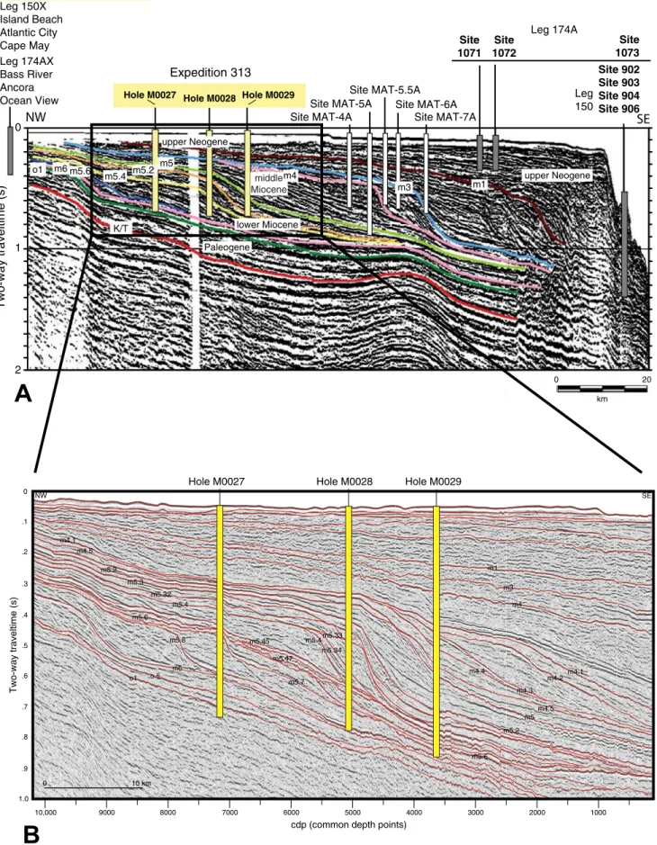
lowstand deposits and (2) provide a large and diversified set of sedimentary facies very sensitive to changes in sea level (Mountain et al., 2009) that can be easily interpreted in terms of paleo–water depths. Three holes were drilled in the inner shelf targeting the upper Oligocene to middle Miocene seismi-cally imaged prograding clinothems (Fig. 2B). The three holes drilled in 34– 36 m of water, 45–67 km offshore, sample a 22-km-long clinothem transect including the topset, foreset, and toeset of several clinothems from 180 to 750 m below seafloor (mbsf).
Building on seismic stratigraphy of Monteverde et al. (2008), Expedition 313 drilled through 25 regionally mapped Oligocene to Miocene seismic sur-faces that correlate to facies changes in the coreholes (Mountain et al., 2010; Inwood et al., 2013; Miller et al., 2013a, 2013b; Browning et al., 2013). The lithostratigraphic description of split cores shows silt-rich supply systems that reveal a notable depletion in clays and a marked difference between the top
and the toe of the clinoform bodies (e.g., Lofi et al., 2013). The topset facies succession shows well-sorted silts and sands deposited in offshore to shore-face, mixed wave- to river-dominated shelf environments. The toe of the clinothems show silts and silty clays deposited below wave base. These sedi-ments are typically interbedded with poorly sorted silts and sands deposited by continuous downslope gravity transport processes such as debris flows and turbidity currents during periods of clinoform rollover and upper slope degradation (Hodgson et al., 2018). The open shelf experienced frequent cycles of dysoxia. In situ and reworked glauconite is a common component of topset and bottomset strata that also show sharp changes in pore water salin-ity. Strontium isotopic ages measured on molluscs and foraminifers, reliable biostratigraphic zonation of multiple fossil groups (foraminifers, dinocysts and nannofossils; Katz et al., 2013; Browning et al., 2013), and specific pollen markers (McCarthy et al., 2013; Kotthoff et al., 2014) verify a nearly continuous
100 200 1000 2000 3000 C ON T I NE N T AL S H E LF New Jersey Long Island Delmarva Peninsula PAL E O ZO I C O U TC R O P C RE T A CE O U S MI O C EN E -73° -72° 39°N 40°N 76°W 75°W 74°W 77°W 50 km Figure 2 Figure 5 Figure 7 Drillsites Onshore ODP
M
ID-A
TLANTICT
RANSECTAMCORDSDP Oil exploration IODP Expedition 313 Seismic Profiles Oc270 CH0698 Ew9009 Drill Sites Offshore ODP M0027 M0028 M0029 Atlantic Cape Cape Bass River Ancora Bethany Beach Millville Ft. Mott 1071 1072 1073 Beach View Island Sea Girt Ocean City 903 904 905 902 906 May Zoo May
United States
Figure 1. Location map of the New Jersey shelf coring sites on land, mid-shelf, and slope used to build up the Mid-Atlantic Transect. The figure shows Holes M0027, M0028, and M0029 drilled during Interna-tional Ocean Discovery Program (IODP)– Inter national Continental Scientific Drilling Program (ICDP) Expedition 313 along with other completed boreholes both onshore and offshore. Tracks of reconnaissance seismic lines relevant to the goals of Expe-dition 313 are also shown. ODP—Ocean Drilling Program; DSDP—Deep Sea Drilling Project; IODP—International Ocean Dis-covery Program; AMCOR—Atlantic Margin Coring Project. Modified from Mountain et al. (2010b) and Kominz et al. (2016).
Research Paper
156
7
Pr
oust et al.
| New Jersey Miocene subaqueous clinothems
GEOSPHERE | Volume 14 | Number 4
Two-way traveltime (s)
0 1 2 o1 m6 m1 middle Miocene m5.2 m5 K/T Site MAT-4A Site 1071 Site 1072 Site 902 Site 903 Site 904 Site 906Site MAT-5A Site MAT-6A
Site MAT-5.5A Leg 174A Leg 150 lower Miocene Leg 150X Island Beach Atlantic City Cape May Leg 174AX Bass River Ancora
Ocean View Hole M0027 Hole M0028 Hole M0029
m5.6 m5.4 upper Neogene upper Neogene 2 0 0 km m3 Site MAT-7A m4 Site 1073
Expedition 313
PaleogeneA
B
NW
SE
0 .1 .2 .3 .4 .5 .6 .7 .8 .9 1.0 Two-way traveltime (s) 0 10 km 10,000 9000 8000 7000 6000 5000 4000 3000 2000 1000 NW SEHole M0027 Hole M0028 Hole M0029
o1 o.5 m4 m3 m1 m6 m5.8 m5.7 m5.6 m5.6 m5.45 m5.47 m5.4 m5.4 m5.34 m5.33 m5.32 m5.3 m5.2 m5.2 m5 m4.1 m4.1 m4.2 m4.3 m4.4 m4.5 m4.5
Onland exposures and drillings
cdp (common depth points)
Figure 2. Drillhole locations projected on a regional seismic line through the New Jersey shelf. (A) R/V Ewing cruise Ew9009 seismic line 1003 through Holes M0027, M0028, and M0029 (yellow subseafloor columns; see Fig. 1 for location). Generalized locations of Ocean Drilling Program boreholes onshore and offshore (gray columns) and alternate sites also suitable for clinothem sampling in deeper waters (sites MAT-4A to MAT-7A, white columns) are also shown. The main key surfaces (colored lines; Cretaceous–Paleogene [Cretaceous–Tertiary, K/T] boundary = ca. 65 Ma, o1 = ca. 33.5 Ma, m5 = ca. 16.5 Ma, m4 = ca. 14 Ma, m3 = ca. 13.5 Ma, and m1 = ca. 11.5 Ma) have been traced from the inner shelf to the slope. The clinoform shape of sediments bracketed by these unconformities is thought to be the result of large sea-level fluctuations (Vail and Mitchum, 1977). (B) R/V Oceanus cruise Oc270 seismic line 529 with superposed seismic sequence boundaries interpreted by Monteverde et al. (2008) and drill depths at each of the three Expedition 313 sites (M0027, M0028, and M0029).
Downloaded from https://pubs.geoscienceworld.org/gsa/geosphere/article-pdf/14/4/1564/4265344/1564.pdf by CNRS_INSU user
record of ~1 m.y. sea-level cycles and climate variations that may explain facies changes along the slopes of the clinoforms. We found no evidence of sea-level drop below the clinoform inflection point—i.e., depositional shelf break or offlap break—but the occurrence of shoreface deposits along the slope of the clinoforms and of deep water facies on their topsets suggest large changes in amplitude of relative sea level in the range of 60 m (Mountain et al., 2010a, 2010b).
DATA AND METHOD
Despite the difficulties of coring the sandy material of the shallow New Jersey shelf, 612 cores were collected at three sites (Sites M0027, M0028, and M0029) with 80% recovery for a total of 1311 m (Mountain et al., 2010a, 2010b). The deepest hole (M0029A) reached 757 mbsf; the oldest sediment (upper-most Eocene) was recovered in Hole M0027A. Besides the cores, the expedi-tion collected wireline logs at the three sites—gamma ray, resistivity, magnetic susceptibility, sonic, acoustic televiewer, and vertical seismic profiles—which, together with multisensor core logs on unsplit cores, provide precise ties be-tween core logs and seismic profiles (Mountain et al., 2010a, 2010b; Miller et al., 2013b). This data set was complemented post-cruise by the shipboard party by visual core descriptions and smear slide analyses, biostratigraphy (calcareous nannoplankton, diatoms, dinoflagellate cysts), magnetostratigra-phy, and pore water geochemistry; paleobathymetry and paleoenvironments inferred from benthic foraminifera assemblages, dinocysts, pollen analyses, and grain size analysis (Ando et al., 2014). Multi-sensor core logger (MSCL) and petrophysical data were directly measured on cores and core sections (Inwood et al., 2013); Sr analyses were performed as an aid to get additional age control on the sediment and to evaluate the length of time represented by key stratal surfaces (Miller et al., 2013b; Browning et al., 2013).
Here we present a detailed analysis of the lithofacies successions and their interpretation in terms of depositional environment based on visual core de-scription. Genetically related facies successions are bounded by unconformi-ties tied to the interpreted seismic line 529 (cruise Oc270) (Monteverde et al., 2008) crossing the three holes, by using MSCL and downhole (impedance) log data (Miller et al., 2013b). In the following, we use the updated version of the stratal ages of Mountain et al. (2010b) provided by Browning et al. (2013).
RESULTS
The most striking feature of the early to mid-Miocene sediments of the New Jersey passive margin, as seen on the seismic line 529 of cruise Oc270, is the clinoform shape of the reflectors (Fig. 2). Here we present a descrip-tion of the main lithofacies of the clinothems sampled in Site M0027, M0028, and M0029 coreholes of Expedition 313 and an interpretation of their
deposi-tional environments (Fig. 3; Supplemental Files [Figs. S1–S3]1). Based on the
established ties between the cores and the Oc529 seismic line (Mountain et al., 2010b; Miller et al., 2013a, 2013b), we reconstruct the lateral facies distribution along a two-dimensional (2-D) dip-oriented line across the margin, and inter-pret their depositional environments, systems tracts, and sequences.
Lithofacies and Depositional Environments
The lithofacies observed in cores are described below from the deep off-shore marine to the shallow marine off-shoreface environments (Table 1). Num-bers in the text refer to the hole and the lithofacies label (e.g., 27-1 refers to Hole M0027 and lithofacies 1; 28-4 refers to Hole M0028 and lithofacies 4; etc.) shown in Figure 3 and with more details in the Supplemental Files (Figs. S1–S3 [footnote 1]).
Offshore Marine Gravity-Flow Deposits—Lithofacies Association 1 (FA1)
Gravity flow deposits are abundant at the base of the three holes (M0027, 480–625 m; M0028, 500–610 m; M0029, 600–730 m; Fig. 3) and in the middle part of Hole M0029 (450–500 m; Fig. 3). Their lithological diversity is very large. They are here tentatively grouped in two broad categories, but a detailed de-scription of their occurrence along the bottomsets of the clinothems can be found in Hodgson et al. (2018).Amalgamated toe-of-slope debrites and turbidites—FA1.1. Lithofacies
association FA1.1 occurs above seismic surfaces at the bottomset of clino-forms (Fig. 3). The lithofacies comprises a few-meters-thick, poorly sorted, glauconitic and quartzitic, medium to coarse sand with angular quartz gran-ules and gravels, clay clasts, and, in places, a muddy matrix. Glauconite con-tent can decrease upsection from 80%–90% (lithofacies 27-4, 28-6) to <40% (28-7), or to 5% with increasing mud content and decreasing quartz grain concentration (29-15). At the base, the facies is homogeneous and well bedded (27-4, 27-5, 28-6, 28-2), alternating with pale brown clay beds with nannofossils, locally cemented by carbonates and bioturbated by clay-lined horizontal and vertical burrows filled by glauconite (up to 87 cm below ero-sion surfaces). The gravel to medium sand beds show crude normal and re-verse grading, with 1-m-high oblique stratification (15° apparent dip) under-lined by muddy lamina cut by clay-filled Chondrites trace fossils (27-5, 28-6) and ripple and low-angle lamination. Upsection, the facies thins and fines upward (rarely coarsening), organized in meter-scale successions (28-7, 27-6, 28-9, 29-9, 29-13, 29-15, 29-18) capped by bioturbated horizons. Parallel and ripple cross-lamination give rise to finer-grained sediment with faint low- energy horizontal lamination, convolution, and laminae with a chaotic pat-tern. Thick- and thin-walled shell fragments are scattered throughout but show signs of severe dissolution. Locally, concretions and quartz granules have a patchy green coating or shattered fabric (e.g., 29-15). No plant debris or mica is observed. m4.1 m4.5 m5 m5.2 m5.3 m5.32 m5.4 / m5.34 / m5.33 m5.6 / m5.5 / m5.47 m5.45 m5.7 m5.8 m6 Sot2 330 320 340 350 360 370 380 390 400 300 310 103R 104R 105R 106R 107R 108R 109R 110R 111R 112R 113R 114R 115R 116R 117R 118R 119R 120R 121R 122R 123R 124R 125R 126R 127R 128R 129R 130R 131R 132R 133R 134R 135R 136R 137R 138R 139R 140R 141R 142R 143R SET 410 420 430 440 450 460 470 480 490 500 510 144R 145R 146R 147R 148R 149R 150R 151R 152R 153R 154R 155R 156R 157R 158R 159R 160R 161R 162R 163R 164R 165R 166R 167R 168R 169R 170R 171R 172R 173R 174R 175R 176R 177R 178X 179R 180R 181R 182R 183R 184R 520 530 540 550 560 570 580 590 600 610 620 630 185R 186R 187R 188R 189R 190R 191R 192R 193R 194R 195R 196R 197R 198R 199R 200R 201R 202R 203R 204R 205R 206R 207R 208R 209R 210R 211R 212R 213R 214R 215R 216R 217R 218R 219R 220R 221R 222R 223R 224R II Sot3 15 15 15 15 15 15 15 METRESLITHOFACIE S Silt
ClaySfineScoarseSmed.pebblesC GRANULOMETRY Fst RstGst PstWst MarnesMst TEXTURE (carb.) 190 200 210 220 230 240 250 260 270 280 290 63H 64H 65X 66X 67X 68X 69X 70X 71H 72H 73X 74X 75X 76X 77X 78X 79R 80R 81R 82R 83R 84R 85R 86R 87R 88R 89R 90R 91R 92R 93R 94R 95R 96R 97R 98R 99R 100R 101R 102R 20 16 16 16 16 16 16 14 12 10 9 13 11 19 18 18 18 17 15 16 15 15 15 15 16 16 14 15 10 15 16 19 19 14 14 10 9 8 7 6 4 5 4 2 3 3 3 2 2 1 3 2 Depositional environments Key surfaces Lower offshore FA1.1 Upper offshore FA1.2
Slope apron (base)
FA2.1a
Slope apron (top) FA2.1b Amalgamated toe of slope debrites FA2.2 Lower shoreface (Qz) FA3.1 Lower shoreface (Gl) FA3.2 Upper shoreface (Qz) FA4.1 Upper shoreface (Gl) FA4.2
Gullies and clinoform-edge fans FA5 Transgressive lag FA6 Systems tracts Seismic surfaces (this study) m5.32 Seismic surfaces (Miller et al., 2013) m5.32 Seismic surfaces (Kominz et al., 2016 m5.32 Falling Stage ST Set 3 Highstand ST Set 2 Transgressive ST Set 1 Lowstand ST Set 4 PALEOBATHYMETRY (from Katz et al., 2013)
0 m20 m40 m60 m80 m100 m 120 m m4.4 / m4.3 m4.5 m5 m5.2 m5.3 m5.33 m5.34 m5.47 / m5.6 m5.45 m5.4 m5.7 m5.8 m6 m4.1 m4.5 m5 m5.2 m5.3 m5.3 m5.33 m5.4 / m5.34 m5.47 m5.45 m5.7 m5.8 m6 m6 Figure S1
1Supplemental Files. Figure S1 is detailed lithological
sections of hole M0027 drawn from the visual core descriptions. Figure S2 is detailed lithological sec-tions of hole M0028 drawn from the visual core de-scriptions. Figure S3 is detailed lithological sections of hole M0029 drawn from the visual core descrip-tions. Please visit https:// doi .org /10 .1130 /GES01545 .S1 or the full-text article on www .gsapubs .org to view the Supplemental Files.
Research Paper
156
9
Pr
oust et al.
| New Jersey Miocene subaqueous clinothems
GEOSPHERE | Volume 14 | Number 4 gggg gg gg gg gg gggg gg gg gg gg gg gg gg gg gg gg gg gggg gg gg gg gg gg 00 200200 400400 600600 TGR (cps) TGR (cps) 00 200200 400400 600600 Core Core recovery recovery Lithology Lithology Unit s Unit s Fa cies Fa cies gggg XXXXXXX XXXXXXX XXXXXXX XXXXXXX XXXXXXX XXXXXXX XXXXXXX XXXXXXX XXXXXXX XXXXXXX XXXXXXX XXXXXXX XXXXXXX XXXXXXX XXXXXXX XXXXXXX XXXXXXX XXXXXXX XXXXXXX XXXXXXX XXXXXXX XXXXXXX gg gggg gggg gggg gggg gggg gggg gg gg gggg gg gggggggg gggggg gggggg gggg gg gggggg gggggg gg gg gg gggggg gg gggg wd wd wd wd XXXXXX XXXXXX XXXXXX XXXXXX wd wdwdwd wd wd XXXXXX XXXXXX gggg gggggggg gg gg gg gg gg gg gg gg gg gggg gg gg ****** 207R 207R 208R 208R 209R 209R 210R 210R 211R 211R 212R 212R 213R 213R 214R 214R 215R 215R 216R 216R 217R 217R 218R 218R 219R 219R 220R 220R221R221R222R222R 223R 223R 224R 224R 167R 167R 168R 168R 169R 169R 170R 170R 171R 171R 172R 172R 173R 173R 174R 174R 175R 175R 176R 176R 177R 177R 178X 178X 179R 179R 180R 180R181R181R182R182R 183R 183R 184R 184R 185R 185R 186R 186R 187R 187R 188R 188R 189R 189R 190R 190R 191R 191R 192R 192R 193R 193R 194R 194R 195R 195R 196R 196R 197R 197R 198R 198R 199R 199R 200R 200R 201R 201R 202R 202R 203R 203R 204R 204R 205R 205R 206R 206R ?? 151R 151R 152R 152R 153R 153R 154R 154R 155R 155R 156R 156R 157R 157R 158R 158R 159R 159R 160R 160R 161R 161R 162R 162R 163R 163R 164R 164R 165R 165R 166R 166R 127R 127R 128R 128R 129R 129R 130R 130R 131R 131R 132R 132R 133R 133R 134R 134R 135R 135R 136R 136R 137R 137R 138R 138R 139R 139R 140R 140R 141R 141R 142R 142R 143R 143R 144R 144R 145R 145R 146R 146R 147R 147R 148R 148R 149R 149R 150R 150R 110R 110R 111R 111R 112R 112R 113R 113R 114R 114R 115R 115R 116R 116R 117R 117R 118R 118R 119R 119R 120R 120R 121R 121R 122R 122R 123R 123R 124R 124R 125R 125R 126R 126R 98R 98R 99R 99R 100R 100R 101R 101R 102R 102R 103R 103R 104R 104R 105R 105R 106R 106R 107R 107R 108R 108R 109R 109R 86R 86R 87R 87R 88R 88R 89R 89R 90R 90R 91R 91R 92R 92R 93R 93R 94R 94R 95R 95R 96R 96R 97R 97R 66X 66X 67X 67X 68X 68X 69X 69X 70X 70X71H71H72H72H 73X 73X 74X 74X 75X 75X 76X 76X 77X 77X 79R 79R 80R 80R 81R 81R 82R 82R 83R 83R 84R 84R 85R 85R 64H 64H 65X 65X 66X 66X VIII VIII VIIB VIIB VIIA VIIA VIB VIB VIA VIA VV IV IV III III IIII 580 590 600 610 620 630 480 490 500 510 520 530 540 550 560 570 430 440 450 460 470 360 370 380 390 400 410 420 430 330 340 350 280 290 300 310 320 270 250 260 200 210 220 230 240 Sd1 580 590 600 610 620 630 480 490 500 510 520 530 540 550 560 570 430 440 450 460 470 360 370 380 390 400 410 420 430 330 340 350 280 290 300 310 320 270 250 260 200 210 220 230 240 Sd1 m6 m6 m5.8 m5.8 m5.33, m 5.4 m5.33, m 5.4 m5.32 m5.32 m5.3 m5.3 m5.2 m5.2 m5 m5 m4.1 m4.1 m5.45 m5.45 1 2 3 2 3 2 3 2 4 5 4 6 7 8 9 10 11 12 10 9 13 14 14 15 15 14 14 16 14 14 14 16 16 15 16 15 16 16 16 16 15 15 15 15 15 14 15 16 17 18 19 18 1819 19 16 15 15 20 1 2 3 2 3 2 3 2 4 5 4 6 7 8 9 10 11 12 10 9 13 14 14 15 15 14 14 16 14 14 14 16 16 15 16 15 16 16 16 16 15 15 15 15 15 14 15 16 17 18 19 18 1819 19 16 15 15 20 m4.5 m4.5 m5.7 m5.7 m5.47, m5.6, m5.5 m5.47, m5.6, m5.5 Depth (m) Depth (m) 630 620 610 600 670 660 650 640 590 580 570 560 550 540 530 520 510 500 490 480 470 460 450 440 430 420 410 400 390 380 370 360 350 340 330 320 310 300 290 280 270 260 250 240 230 220 630 620 610 600 670 660 650 640 590 580 570 560 550 540 530 520 510 500 490 480 470 460 450 440 430 420 410 400 390 380 370 360 350 340 330 320 310 300 290 280 270 260 250 240 230 220 1 2 3 1 1 1 4 5 5 18 6 6 7 8 9 10 11 10 11 12 11 13 14 15 16 16 17 18 19 17 19 18 20 21 16 22 23 24 25 26 27 16 16 28 29 30 31 1 2 3 1 1 1 4 5 5 18 6 6 7 8 9 10 11 10 11 12 11 13 14 15 16 16 17 18 19 17 19 18 20 21 16 22 23 24 25 26 27 16 16 28 29 30 31 gg gggg gg wd wd wd wd ggwdwd wd wdp p p p p p wd wd xxxxxxwdwd p p xx xx wd wd wd wd xxxxxxxxx xxxxxxxxx xxxxxxx xxxxxxx 00 100100 200200 300300 TGR (cps) TGR (cps) gg gg gg gg gg gg XXXXXX XXXXXX gg gg gg gg gg gg gg gg gg gg gg gg gg gg xxxxxxx xxxxxxx gg gg gg gg gg gg gg gg gg gg gg xxxxxxx xxxxxxxgggg gg gggg gg wd wd wd wd wd wd wd wd wd wd wd wd wd wd wd wd wd wd gg gggg wd wdgggg XXXXXX XXXXXX XXXXXX XXXXXX XXXXXX XXXXXX XXXXXX XXXXXX gg gg gg wd wd wd wd wd wd wd wd wd wd wd wd wd wd wd wd wd wd wd wd xx gg gg gg gg gg gg gg gg gg gggg gg gg gg xxxxxxx xxxxxxxgg wdwd wd wd gg gg gg gg gg gg gg gg gg gg gg gg g g g g gg wd wd xxxxxxxxxxxxxxxx xxxxxxxxxxxxxxxx xxxxxxxxxxxxxxxx xxxxxxxxxxxxxxxx xxxxxxxxxxxxxxxx xxxxxxxxxxxxxxxx gggg pp xxx xxxx xxxxx xxx xxxx xxxxx xxxxxxxxxxxxxxxx xxxxxxxxxxxxxxxx xxxxxxxxxxxxxxxx xxxxxxxxxxxxxxxx xxxxxxxxxxxxxxxx xxxxxxxxxxxxxxxx gg xxxxxxxxxxxxxxxx xxxxxxxxxxxxxxxx xxxxxxxxxxxx xxxxxxxxxxxxxxxx xxxxxxxxxxxxxxxx xxxxxxxxxxxxxxxx xxxxxx xxxxxxxxxxxxxxxx xxxxxxggwdwdgg wd wd wd wd wd wd 147R 148R 149R 150R151R 152R 153R 154R 155R 156R 157R 158R 159R 160R 161R 161R 162R 163R 164R 165R 166R 167R 168R 169R 170R171R 126R 127R 128R 129R 130R 131R 132R 133R 134R 135R 136R 137R 138R 139R 140R 141R 142R 143R 144R 145R 146R 103R 104R 105R 106R 107R 108R 109R 110R 111R 112R 113R 114R 115R 116R 117R 118R 119R 120R 121R 122R 123R 124R 125R 90R 91R 92R 93R 94R 95R 96R 97R 98R 99R 100R 101R 102R 68R 69R 70R71R72R 73R 74R 76R 77R 78R 79R 80R 80R 81R 82R 83R 84R 85R 86R 87R 88R 89R ? ? ? C.D. C.D. 53R 54R 55R 56R 57R 58R 59R 60R 61R 62R 63R 64R 65R 66R 67R 29R 30R 31R 32R 33R 34R 35R 36R 37R 38R 39R 40R 40R 41R 49R 50R 51R 52R 13R 14R 15R 16R 18R 19R 20R 21R 22R 23R 24R 25R 26R 27R 28R 2R 3R 4R 5R 6R 7R 8R 9R 10R 11R 12R 147R 148R 149R 150R151R 152R 153R 154R 155R 156R 157R 158R 159R 160R 161R 161R 162R 163R 164R 165R 166R 167R 168R 169R 170R171R 126R 127R 128R 129R 130R 131R 132R 133R 134R 135R 136R 137R 138R 139R 140R 141R 142R 143R 144R 145R 146R 103R 104R 105R 106R 107R 108R 109R 110R 111R 112R 113R 114R 115R 116R 117R 118R 119R 120R 121R 122R 123R 124R 125R 90R 91R 92R 93R 94R 95R 96R 97R 98R 99R 100R 101R 102R 68R 69R 70R71R72R 73R 74R 76R 77R 78R 79R 80R 80R 81R 82R 83R 84R 85R 86R 87R 88R 89R ? ? ? C.D. C.D. 53R 54R 55R 56R 57R 58R 59R 60R 61R 62R 63R 64R 65R 66R 67R 29R 30R 31R 32R 33R 34R 35R 36R 37R 38R 39R 40R 40R 41R 49R 50R 51R 52R 13R 14R 15R 16R 18R 19R 20R 21R 22R 23R 24R 25R 26R 27R 28R 2R 3R 4R 5R 6R 7R 8R 9R 10R 11R 12R gg VII VI VC VB VA IV IIID IIIC IIIB IIIA IID IIC IIB IIA VII VI VC VB VA IV IIID IIIC IIIB IIIA IID IIC IIB IIA 00 100100 200200 300300 Core Core recovery
recovery UnitsUnits LithologyLithology
Fa cie s Fa cie s m4.1 m4.1 m5.3 m5.3 m5.32, m5.33 m5.32, m5.33 m5.4 m5.4 m5.34 m5.34 m5.45 m5.45 m5.47 m5.47 m5.7 m5.7 m5.8 m5.8 m5 m5 m5.6 m5.6 m5.5 m5.5 m4.5 m4.5 m5.2 m5.2 Depth (m) Depth (m) gg xxxxxxxxxxxxxxx xxxxxxxxxxxxxxxxxxxxxxxxxxxxxxxxxxxxxxxxxxxxxgggg gg gg xxxxxxxxxxxxxxx xxxxxxxxxxxxxxx xxxxxxxxxxxxxxx xxxxxxxxxxxxxxx XX XX XX XX XX xxxxxxxxxxxxxxx xxxxxxxxxxxxxxx XXXXXXXXXX XXXXXXXXXX XXXXXXXXXX XXXXXXXXXX XXXXXXXXXX XXXXXXXXXX gg gg gg xx 0 200 400 0 200 400 XXXXX XXXXX XXXXX XXXXXwdwd gg XXXXX XXXXX XXXXX XXXXX XXXXX XXXXXwdwd gggg XXXXXXXXXX XXXXXXXXXX XXXXX XXXXXgg XXXXX XXXXXwdwd gg xxxxxxxxxxxxxxx xxxxxxxxxxxxxxxgggg gg gg ggwdwd gg xxxxxxxxxxxxxxx xxxxxxxxxxxxxxx xxxxxxxxxxxxxxx xxxxxxxxxxxxxxx xxxxxxxxxxxxxxx xxxxxxxxxxxxxxx gggggg gggggg xxxxxxxxxxxxxxx xxxxxxxxxxxxxxx gggggg gggggg gggggg gggggg gggggg ggggwdwdgg xxxxxxxxxxxxxxx xxxxxxxxxxxxxxx xxxxxxxxxxxxxxx xxxxxxxxxxxxxxx xxxxxxxxx xxxxxxxxx xxxxxxxxxxxxxxx xxxxxxxxxxxxxxx xxxxxxxxxxxxxxx xxxxxxxxxxxxxxx gggg xxxxxxxxx xxxxxxxxx wd wd gg gg gg gg gggggg gg XX gggg gg gg wd wd wd wd wd wd wd wd gg wd wd wd wd gg wd wd xxxxxxxxxx xxxxxxxxxx gggg gggg gggg gggg gg gg wd wd wd wd gg gg gg xx gg gg wd wd wd wd gggg xxxxxxxxxx xxxxxxxxxx wd wd gg wd wd XXXXXX XXppXX pp XXXX XX pp wd wd XX XXXX wd wd pp pp pp gg gg gg wd wd wd wd wd wd gg xx 196R 196R 195R 195R 197R 197R 198R 198R 199R 199R 200R 200R 201R 201R 202R 202R 203R 203R 204R 204R 205R 205R 206R 206R 207R 207R 208R 208R 209R 209R 210R 210R 211R 211R 212R 212R 213R 213R 214R 214R 215R 215R 216R 216R 217R 217R 177R 177R 178R 178R 179R 179R 180R 180R 181R 181R 182R 182R 183R 183R 184R 184R 185R 185R 186R 186R 187R 187R 188R 188R 189R 189R 190R 190R 191R 191R 192R 192R 193R 193R 194R 194R 158R 158R 159R 159R 160R 160R 161R 161R 162R 162R 163R 163R 164R 164R 165R 165R 166R 166R 167R 167R 168R 168R 169R 169R 170R 170R 171R 171R 172R 172R 173R 173R 174R 174R 175R 175R 176R 176R 177R 177R 148R 148R 149R 149R 150R 150R 151R 151R 152R 152R 153R 153R 154R 154R 155R 155R 156R 156R 157R 157R 131R 131R 132R 132R 133R 133R 134R 134R 135R 135R 136R 136R 137R 137R 138R 138R 139R 139R 140R 140R 141R 141R 142R 142R 143R 143R 144R 144R 145R 145R 146R 146R 147R 147R 118R 118R 119R 119R 120R 120R 121R 121R 122R 122R 123R 123R 124R 124R 125R 125R 126R 126R 127R 127R 128R 128R 129R 129R 130R 130R 131R 131R 98R 98R 99R 99R 100R 100R 101R 101R 102R 102R 103R 103R 104R 104R 105R 105R 106R 106R 107R 107R 108R 108R 109R 109R 110R 110R 111R 111R 112R 112R 113R 113R 114R 114R 115R 115R 116R 116R 117R 117R 81R 81R 82R 82R 83R 83R 84R 84R 85R 85R 86R 86R 87R 87R 88R 88R 89R 89R 90R 90R 91R 91R 92R 92R 93R 93R 94R 94R 95R 95R 96R 96R 97R 97R 63R 63R 64R 64R 65R 65R 66R 66R 67R 67R 68R 68R 69R 69R 70R 70R 71R 71R 72R 72R 73R 73R 74R 74R 75R 75R 76R 76R 77R 77R 78R 78R 79R 79R 80R 80R 50R 50R 51R 51R 52R 52R 53R 53R 54R 54R 55R 55R 56R 56R 57R 57R 58R 58R 59R 59R 60R 60R 61R 61R 62R 62R xxxxxxxx xxxxxxxx wd wd wd wd wd wd wd wd wd wd Core Core recovery
recovery LithologyLithology
VII VI VE VD VC VB VA IV III IID2 IID1 IIC IIB2 IIB1 IIA3 IIA2 IIA1 IE VII VI VE VD VC VB VA IV III IID2 IID1 IIC IIB2 IIB1 IIA3 IIA2 IIA1 IE Fa cies Fa cies 1 2 3 4 5 6 16 16 16 7 8 9 10 11 11 12 13 5 14 15 15 4 16 17 4 18 16 19 20 20 21 20 22 23 23 23 24 23 3 3 25 26 27 28 29 30 31 1 2 3 4 5 6 16 16 16 7 8 9 10 11 11 12 13 5 14 15 15 4 16 17 4 18 16 19 20 20 21 20 22 23 23 23 24 23 3 3 25 26 27 28 29 30 31 690 700 710 720 730 740 750 680 670 660 650 640 630 620 610 600 590 580 570 560 550 540 530 520 510 500 490 480 470 460 450 440 430 420 410 400 390 380 370 360 350 340 330 320 310 300 290 280 690 700 710 720 730 740 750 680 670 660 650 640 630 620 610 600 590 580 570 560 550 540 530 520 510 500 490 480 470 460 450 440 430 420 410 400 390 380 370 360 350 340 330 320 310 300 290 280 00 200200 400400 TGR (cps) TGR (cps) m5.8 m5.8 m5.7 m5.7 m5.6 m5.6 m5.5 m5.5 m5.47 m5.47 m5.45 m5.45 m5.33 m5.33 m5.3 m5.3 m5.2 m5.2 m5 m5 m4.5 m4.5 m4.4 m4.4 m4.3 m4.3 m4.2 m4.2 m5.4, m5.34 m5.4, m5.34 m5.32 m5.32 m4.1 m4.1 Depth (m) Depth (m) UnitsUnits Sand(stone) Sand(stone) Lithology Lithology Glauconite sand(stone) Glauconite sand(stone) Silt(stone) Silt(stone) Clay(stone) Clay(stone) Depositional environments
Depositional environments Seismic SetsSeismic Sets Key surfacesKey surfaces Stack of clinothems
boundary Stack of clinothems
boundary Clinothem / seismic unit
boundary Clinothem / seismic unit
boundary Set boundary Set boundary Falling stage ST
set 3
set 3 Falling stage ST
set 3
Highstand ST and mud-drape
set 2
set 2 Highstand ST and mud-drape set 2 Transgressive ST set 1 set 1 Transgressive ST set 1 Lowstand ST set 4 set 4 Lowstand ST set 4 Lower offshore
FA2.1 Lower offshore
FA2.1
Upper offshore
FA2.2 Upper offshore
FA2.2
Slope apron (lower)
FA1.2a Slope apron (lower)
FA1.2a
Slope apron (upper)
FA1.2b Slope apron (upper)
FA1.2b
FA1.2b
Amalgamated toe-of-slope debrites
FA1.1 Amalgamated
toe-of-slope debrites
FA1.1
Lower shoreface (Qz)
FA3.1 Lower shoreface (Qz)
FA3.1
Lower shoreface (Gl)
FA3.2 Lower shoreface (Gl)
FA3.2
Upper shoreface (Qz)
FA4.1 Upper shoreface (Qz)
FA4.1
Upper shoreface (Gl)
FA4.2 Upper shoreface (Gl)
FA4.2
Gully and clinoform-edge fans
FA5 Gully and clinoform-edge fans
FA5
Transgressive lag
FA6 Transgressive lag
FA6
Hole M0027
Hole M0028
Hole M0029
Figure 3. Simplified lithologic columns of the three Expedition 313 Holes M0027, M0028, and M0029 with the downhole total gamma ray log (TGR; cps—count per sec-ond); the inferred location on cores of the seismic unconformities (m4.1 to m6) observed on R/V Oceanus cruise Oc270 seismic line 529, based, with minor changes, on previous works of Mountain et al. (2010b), Miller et al. (2013a, 2013b), and Browning et al. (2013); and interpreted depositional environments and systems tracts (STs). A simplified description of the lithofacies, annotated with the number shown in colored boxes for each hole (e.g., “27-1” is lithofacies 1 in Hole M0027, “28-4” is lithofacies 4 in Hole M0028, etc.), can be found in Table 1 and in the detailed sections in the Supplemental Files (Figs. S1, S2, and S3; footnote 1). Numbers referred to in the core recovery columns are the core section numbers. The grey areas next to the core section numbers show the importance of the sediment recovery in each section. The location of the sediment gaps is unknown, so core recovery is arbitrarily affected in depth to the top of each section. Gl—glauconite, Qz—quartz.
Downloaded from https://pubs.geoscienceworld.org/gsa/geosphere/article-pdf/14/4/1564/4265344/1564.pdf by CNRS_INSU user
TABLE 1. SUMMARY OF THE MAIN LITHOFACIES AND LITHOFACIES ASSOCIATIONS RECOGNIZED IN HOLES M0027, M0028, AND M0029 ON THE NEW JERSEY SHELF, WITH THEIR DEPOSITIONAL ENVIRONMENT INTERPRETATIONS Lithofacies association
Lithofacies Lithology
Sedimentary structures Glauconite content Bioturbation Observations Comments
M0027 M0028 M0029 Grain size Sorting Grading
FA1—Of fshor e mar ine gr avity flow deposits FA1.1— Amalgamated toe of slope debrites 27-4; 27-5; 27-6 28-2; 28-6; 28-7; 28-9 29-9; 29-13; 29-15; 29-18 Medium to
coarse sand Poor Variable;usually
normal
Well stratified; massive to oblique stratification; ripple and low-angle laminations; parallel and ripple cross-laminations; convolute lamination Abundant Moderate; presence of glauconite-filled burrows
Angular quartz granules and gravels; clay clasts; muddy matrix locally; clay beds with nannofossils; thick- and thin-walled shell fragments with sign of severe dissolution; quartz granules and concretions may have a patchy green coating; no plant debris or mica Healing phase FA1.2— Slope apron deposits FA1.2a 27-2; 27-3 28-4;28-5 29-3; 29-5; 29-8; 29-17 Muddy medium to coarse sand with centimeter-thick clay beds
Poor Variable;
reverse and normal
Generally massive; subhorizontal laminations; ripple laminations; contorted and convolute laminations Abundant; mix of mature and immature grains Locally strong; underlines basal erosional contact
Dispersed granules; local concentration of pebbles; possible basal lag of granules; mud-supported granule and pebble sands within clay beds; variable amount of shell fragments, benthic foraminifers, wood and plant debris, and mica flakes; local presence of articulated shells and well-preserved benthic foraminifers
Lower fan FA1.2b 27-1 28-1 29-1; 29-4; 29-6; 29-7; 29-10; 29-11; 29-12 Fine to medium sand to silty clay
Good Normal Rare ripple-scale cross-laminations;
remnant of planar laminations mix of mature Abundant;
and immature grains Moderate; presence of glauconite-filled burrows
Floating coarse and very coarse quartz sand and glauconite grains; foraminifers; thin-walled shell fragments; thick-thin-walled shell fragments with sign of severe dissolution; traces of plant debris and mica
Upper fan FA 2—St or m- and ri ve r-in fluenced of fsho re ma ri ne deposits FA2.1— Lower offshore deposits FA2.1a 27-7; 27-8 28-3; 28-10; 28-12 29-2 Clayey silt to
very fine sand Good Reverse Poorly laminated to ripple cross-laminations and low-angle to planar
horizontal laminations
Trace; mostly in burrow
infills
Weak Nannofossil bearing; plant debris and mica
flakes; rare carbonate concretions; intact or fragmented thin-shelled bivalves; thin normally and inversely graded sand beds; pyrite; lack of abundant colloidal organic matter River-influenced lower offshore (prodelta) FA2.1b 27-16; 27-17; 27-19; 27-20 28-8; 28-21; 28-23; 28-24; 28-31 29-14; 29-16; 29-19; 29-21; 29-26; 29-28 Clayey silt to
very fine sand Good Reverse Soft-sediment contorted beddings;centimeter-scale silt and very fine
sand beds
Abundant;
dispersed Pervasive Macroscopic plant-lignite debris and mica grains; abundant benthic foraminifers; rare
gastropod and bivalve shell fragments; pyrite Storm-influenced lower offshore FA2.2— Upper offshore deposits FA2.2a 27-9 28-11
Silt to fine sand Variable Reverse Parallel and climbing ripple laminations; centimeter-scale reverse and normal grading with low-angle lamination above swaley scoured surfaces
Trace Weak Abundant plant debris; scattered pebbles and
granules; millimeter- to centimeter-scale fining-up silt and very fine sand beds
River-influenced upper offshore (prodelta) FA2.2b 27-15 28-22;28-25; 28-29 29-20; 29-22; 29-23; 29-27 Silty clay to
medium sand Variable Reverse Low-angle planar laminations;hummocky cross-stratification;
ripple cross-laminations Trace Strong; underlines internal erosion surfaces
Abundant macroscopic plant debris and mica grains; granules; gastropod and bivalve shell fragments; shell beds; benthic foraminifers; millimeter- to centimeter-scale fining-up sand beds and shell layers
Storm-influenced upper offshore
Research Paper
1571
Proust et al. | New Jersey Miocene subaqueous clinothemsGEOSPHERE| Volume 14 | Number 4
The basal graded beds with angular quartz and rounded glauconite in in-clined beds and the well-stratified succession with nannofossils in clay lamina suggest a sediment supply via sediment gravity flows (turbidity currents and debris flows) in a deep water environment (well below wave base). The appar-ent cross-bedding may indicate a channelized context where turbidity currappar-ents built dune-scale migrating bedforms on the toe-of-clinoform slope. Burrows and clay laminae show that the dune-scale bedforms migrated episodically, rather than from sustained flows. The sedimentary structures in the quartz-rich glauconite sands point to some winnowing of sediment at the seafloor, which may have favored the authigenesis of glauconite grains, their relative concentration, and then possibly their cementation with carbonate along irreg-ular erosion surfaces. Sediment was likely sourced from a clinoform rollover location that may have been exposed, as the subangular nature of the quartz sand grains point to a very early burying of freshly eroded material. This basal part of FA1.1 is interpreted as a basal channel lag, recording bypass along ero-sion surfaces (Stevenson et al., 2015).
The upper part of FA1.1 is well organized in meter-scale graded succes-sions, but it is still poorly sorted, with a mix of quartz, glauconite, and shell fragments with traces of dissolution in a muddy matrix. These are probable indications of downslope gravity sediment transport. The fining-upward trend together with the suite of sedimentary structures showing a progressive de-crease in the energy of transport (horizontal parallel lamination, cross-bedding, and low-energy planar lamination) point to a probable channelized transport of a stack of debrites and turbidites at the toe of a clinoform slope apron. The lack of mica and plant debris is noticeable and might indicate a progressive overall retreat of the regional river outlets. The gradational thinning and fining of beds uphole indicate a possible sediment supply response to transgression in an overall marine onlap. Those facies likely were emplaced below the maximum storm wave base (i.e., 80–120 m water depth) as suggested by the lack of traces of hydraulic reworking by waves.
Slope apron deposits—FA1.2. Lithofacies association FA1.2 comprises a
wide range of facies that are usually arranged as glauconite-rich deca
meter-TABLE 1. SUMMARY OF THE MAIN LITHOFACIES AND LITHOFACIES ASSOCIATIONS RECOGNIZED IN HOLES M0027, M0028, AND M0029 ON THE NEW JERSEY SHELF, WITH THEIR DEPOSITIONAL ENVIRONMENT INTERPRETATIONS (continued) Lithofacies association
Lithofacies Lithology
Sedimentary structures Glauconite content Bioturbation Observations Comments
M0027 M0028 M0029 Grain size Sorting Grading
FA3—Lo w er shor eface deposits FA3.1 27-10 28-13; 28-14; 28-27 29-24; 29-25 Silt to medium
sand Good Reverse Current ripple lamination; low-angle oblique laminations; hummocky
cross-stratification capped by mud lamina; symmetrical-aggradational ripple laminations at top of beds
Trace Moderate Rich in coarse sand, mica, and macroscopic
plant debris; granules; shell hash layers;
FA3.2 28-17;
28-19 medium sandMuddy silt to Poor Reverse Hint of laminations delineated by shell lags Abundant Weak Shell hash layers; scattered plant debris; benthic foraminifers;
Abundant glauconite FA4—Upper shor eface deposits FA4.1 27-11; 27-12 28-15; 28-28 29-29; 29-30; 29-31 Medium to
coarse sand Good Reverse Massive; high-angle trough cross-bedding; low-angle laminations;
remnant of deeply scoured or cemented channelized erosion surfaces
Trace Weak Subangular granules; mica, wood, plant
debris; dispersed shell fragments; plant debrisAbundant
and micas Abundant plant debris and mica FA4.2 27-13 28-18 Medium to very
coarse sand Poor Reverse Massive; sparse high-angle cross-bedding concentration Abundant;
increase upward
Weak Granules; dispersed shell fragments; scoured
surfaces underlined by coarse quartz sand lamina; local carbonate-cemented horizons
Abundant glauconite FA5—Gullies and clinof or m-edge fans 28-20; 28-26 Coarse sand intercalated with clay beds
or lamina
Poor Reverse Massive; numerous internal erosion
surfaces concentration Abundant;
increase upward; glauconite-filled burrows
Pervasive Mix of mud, coarse sand, and gravel; low
in mica and organic matter; deficient in silt to medium sand; shell molds; angular to rounded pebbles and granules; rip-up clasts Coarse, rapid sedimentation and incisions FA 6— Tr ansgr essiv e lag deposits 27-14; 27-18 28-16; 28-30 Very coarse sand to clayey silts
Poor Normal Massive; sharp based Abundant Pervasive Large pieces of wood and plant debris;
subangular quartz and glauconite granules; large thick-walled shells; mica; benthic foraminifers; shell layers in clayey silts
Marine ravinement
Note: Lithofacies identifiers (e.g., 27-14) refer to lithofacies 14 in Hole M0027. Lithofacies are shown in Figure 3 and with more details in the Supplemental Files (Figs. S1–S3) (see text footnote 1).
Downloaded from https://pubs.geoscienceworld.org/gsa/geosphere/article-pdf/14/4/1564/4265344/1564.pdf by CNRS_INSU user
thick fining-upward successions. A distinction is made between coarse-grained deposits (FA1.2a) and the overlying silty-clay deposits (FA1.2b). FA1.2a is composed of stacked, meter- to 10-m-thick coarsening- and/or fining-up-ward successions. The coarsening-upfining-up-ward succession (lithofacies 27-2, 28-4, 28-5, 29-5, 29-8, 29-17) is made up of homogeneous, poorly sorted, coarse-grained quartz and glauconitic (5%–10% to 30%) sand with dispersed quartz granules, concentrations of pebbles (up to 15%), and common weak normal grading; granule and pebble grains tend to be less rounded than sand-grade grains. The fining-upward successions (27-3, 28-5, 29-3, 29-5, 29-17) are coarse- to medium- grained quartz and glauconitic (up to 25%–60%; 27-3) sand lying on a coarse basal lag with granules along an erosive or bioturbated surface. The original subhorizontal or ripple lamination with normal grading are in places largely obscured by bioturbation (e.g., Planolites, Teichichnus, Diplocraterion, and Zoophycos; 27-3) and dish, contorted, and convolute lamination. These coarsening-upward–fining-upward successions are locally interbedded with mud-supported granule and pebble sands with centimeter-thick clay beds (e.g., 29-3). Glauconite grains are a mix of pale-green (immature) granules and smaller black grains (mature). FA1.2b is fining-upward brown silt to silty clay with glauconitic, fine- to medium-grained sand beds, floating coarse and very coarse quartz and glauconite sand grains (29-10), foraminifers and thin-walled shells, traces of mica, and plant debris. Granules and aggregates of pale-green (immature) and subangular glauconite are observed with fine-sand grains of dark green and subrounded glauconite (mature). The sediment is moderately bioturbated with identifiable Chondrites and Planolites (Fig. 4C) and at one place a 30-cm-long Thalassinoides burrow (27-1). Glauconite is commonly concentrated in burrows (vertical burrows and Teichichnus) along erosion surfaces together with rare shell fragments, benthic foraminifers, and disseminated pyrite but including quartz granules (29-11, 29-12) or not (29-7). The sand beds form weakly normally or reversely graded layers with rare ripple-scale cross-lamination (29-4, 29-6). Thick-walled shells occur but show signs of severe dissolution (29-12).
FA1.2a facies are dominated by moderately to poorly sorted, coarse
sand-prone sediment with dispersed granules and pebbles and local concentra-tions of gravel. Weak normal grading supports the partial transformation of debris flows into high-density turbidity currents, but the general poor sorting can be attributed to mixing through bioturbation and/or cohesive debris flow deposition, as shown by the presence of muddy sand with floating granules and pebbles. Centimeter-thick clay and sand interbeds might represent wan-ing-stage deposits. These poorly sorted coarse sediments are interpreted as high-concentration flows of coarse material eroded from updip positions set-tled at the toe of a clinoform slope apron. These facies may correspond to simple coalesced toe-of-slope fans. The presence of micas and plant debris in the finer FA1.2b is indicative of a distant but quasi-permanent river sediment input on the shelf. The abundance, in places exclusive (29-7), of glauconite grains—either (1) dark green, well-rounded and subangular, and broken, or (2) pale green, in situ aggregates—as well as thick shells with traces of disso-lution (29-12), points to temporary local deep marine starved conditions. The
common concentration of the glauconite grains, together with foraminifers or quartz sand grains, in burrows along erosion surfaces points to occasional current-swept floor conditions, which probably in turn favors the generation of the glauconite. The glauconite grains can be produced both in situ or re-worked from the clinoform slope (e.g., Hesselbo and Huggett, 2001). The com-mon occurrence of fining-upward, centimeter- to decimeter-thick sand beds (29-10, 29-12), or thick mud (29-7) with floating coarse (29-10) to granule-size (29-12) quartz and glauconite grains clearly indicates either a component of downslope transport of clastic sediment in dilute turbidity currents or a stack of poorly mature, cohesive(?) debris flows provided by the slope of a clinoform. Overall the decameter-thick vertical stack of FA1.2a and FA1.2b corresponds to the development of fans on the bottomsets of clinoforms that develop below the maximum storm wave base (i.e., 80–120 m water depth) as suggested by the lack of traces of hydraulic reworking by waves.
Storm- and River-Influenced Offshore Marine Deposits—FA2
Offshore marine deposits consisting of marine silts and silty clays are widely distributed in the three holes. They encompass a large number of facies deposited below storm wave base (lower offshore, FA2.1) and between fair-weather and storm wave base (upper offshore, FA2.2). In the literature, this “upper offshore” domain is often termed the “offshore-shoreface transi-tion” (as used by Mountain et al. [2010b]). In cores, lower (FA2.1) and upper (FA2.2) offshore deposits are either river- (FA2.1a, 2.2a) or storm- (FA2.1b, 2.2b) influenced.
River flood–influenced deposits. The river-influenced deposits consist of
coarsening- and thickening-upward meter- to 10-m-thick successions of silty clay to fine to medium quartz sand with abundant mica, plant debris, shell fragments (lithofacies 28-3, 28-12), sponge spicules, and diatoms. The silty clays (FA2.1a) are nannofossil bearing. They can be tan colored (29-2) show-ing micro-laminated clay-rich layers (28-12). Sandier beds are parallel or ripple laminated, and normally (28-3, 28-10, 28-12) to inversely graded (28-3, 28-10) with gradational boundaries (28-3). Bioturbation is absent in clay-rich layers but obscures laminations in sands. Identified frequent burrows include Chon
drites and Planolites but are predominantly simple meniscate backfilled forms,
e.g., Teichichnus (29-2) or Taenidium (Fig. 4A), filled by glauconite (28-3) or replaced by pyrite that may mimic fecal pellets (?Ophiomorpha). Also present are common precompactional carbonate concretions (29-2, 28-3, 27-7, 28-3). The silt to fine sands (FA2.2a) show abundant plant debris, scattered pebbles and granules (28-11), parallel and climbing ripple lamination, and centi meter-scale reverse and normal grading, with low-angle lamination above a swaley scoured surface.
FA2.1a lacks abundant colloidal organic matter, but the abundance of plant
debris and mica indicates a fluvial source for the sediment. The well-laminated silty clays suggest that the depositional environment was probably very quiet and periodically subject to dysoxic bottom waters, as shown by the presence
Research Paper
1573
Proust et al. | New Jersey Miocene subaqueous clinothemsGEOSPHERE| Volume 14 | Number 4
cm 91 87 89 93 95 cm 44 40 42 cm 75 80 90 85 70 65 100 105 95
A
B
C
D
E
cm 55 60 65 50 45 cm 35 40 50 45 30 25 60 65 55 80 75 70 20Figure 4. Core photographs illustrating some of the main facies end members observed in Holes M0027, M0028, and M0029. (A) Interbeds of clay, silt, and very fine-grained sand with a meniscate backfilled burrow (Taenidium at 90–91cm) in river-influenced lower off-shore deposits (Hole M0028, lithofacies 28-3; ~616–619 m, section 313-M0028-154R, 87– 95 cm). (B) Silty very fine sand in lower offshore storm-influenced deposits (Hole M0029, lithofacies 29-16; ~505–507 m, section 313-M0029–127R-2, 40–45 cm) showing a
Teichich-nus burrow at 42 cm. (C) Silty very fine sand with glauconitic sand-filled burrows and Chondrites in the starved slope apron deposits (Hole M0027, lithofacies 27-1; ~626–632 m,
section 313-M0027–223R-1, 65–105 cm). (D) Sharp-based two-part sand bed, with a lower clean sand division (64–59 cm) with shell fragments concentrated at the top and no bio-turbation, and an upper silty sand division (59–54 cm) with low-angle laminations, clay, and no bioturbation. Above 54 cm is muddy and bioturbated fine sand (Hole M0028, litho-facies 28-13, ~417–420 m, section 313-M0028-80R-2). These are interpreted as combined flow deposits under the influence of geostrophic (lower part) and storm wave–generated (upper part) currents. (E) Bioturbated shelly fine sand interbedded with silty clay possibly deposited in lagoonal and barrier beach environments (Hole M0029, lithofacies 29-30, ~288–292, section 313-M0029-53R-2, 20–80 cm).
Downloaded from https://pubs.geoscienceworld.org/gsa/geosphere/article-pdf/14/4/1564/4265344/1564.pdf by CNRS_INSU user
of concretions that excluded burrowing fauna. At times of better oxygenation, the infauna was dominated by horizontally mining deposit-feeding organisms. The gradational upper and lower boundaries and local basal reverse grad-ing of the very fine, parallel- and ripple-laminated sand beds, as well as the milli meter-scale clay-silt laminations in the clay, point to a river flood origin of deposition with a possible seasonality. The depositional environment is in-terpreted as river-dominated lower offshore (prodelta) settings. FA2.2a shows indications of hydraulic sediment transport on the seafloor (parallel, climbing ripple lamination) and also the possible distal influence of storms (low-angle lamination on swaley scoured surfaces) indicative of a progressive shallowing from the lower to the upper offshore environments.
Low-energy, storm-influenced deposits. The storm-influenced deposits
consist of coarsening-upward, meter- to 10-m-thick successions of silty clay to quartz and glauconitic sands with gastropods (e.g., Turritella), thin-walled bivalve shell fragments, and benthic foraminifers. The clayey silt to silty clay (e.g., 27-16, 28-8, 28-21, 28-23) (FA2.1b) contains abundant dispersed glauco-nite sand grains and macroscopic plant debris and mica grains, landward of clinoform rollover points (e.g., 27-16, 27-17). In the upper part of the three holes is a dark brown massive clay with abundant benthic foraminifers, rare shell fragments, faint lamination defined by weak concentrations of plant debris, bioturbation (Planolites), and scattered calcilutite beds (27-17), and a pale and gray-yellow-brown color-banded clay with Chondrites, pyritic and silty lami-nae, and common soft-sediment contorted bedding at different scales (28-31, 29-26). Sporadic millimeter- to centimeter-scale silts and very fine sand beds with faint laminae and a fining-upward trend are locally present within the silty clay (e.g., 27-19, 29-16). Bioturbation is usually pervasive (29-14, 29-16, 29-21), and burrow infills locally contain coarse glauconite and quartz sand or granules (e.g., 29-16). The thoroughly bioturbated silty clays are interbedded with coarsening- (28-25) or fining-upward (28-22, 29-22, 29-27) successions of centimeter-scale, silty to very fine sand beds (FA2.2b). Bioturbation is perva-sive in silty clay beds and also underlines erosion surfaces (Chondrites, Plano
lites, Cylindrichnus, Teichichnus burrows; Fig. 4B) (27-15, 29-23) or crosscuts
the lamination (28-22). Sand beds are normally graded (29-22, 29-23) with low-angle shell layers (28-25, 29-20), hummocky cross-stratification (27-15, 28-22), and ripple and low-angle cross-laminations (28-29). FA2.2b typically overlies FA2.1b; together they form meter- to decimeter-thick coarsening-up-ward stacks of facies.
The silty clay material of facies FA2.1b shows indications of deep lower offshore marine conditions with an abundant autochthonous fauna and ac-tive bioturbation, and episodic starvation (in situ glauconite), but no trace of hydraulic reworking by wave action. In places, the banded character of the clays with Chondrites and pyrite and the presence of calcilutite beds confirm periodic sediment-starved bottom conditions. Color banding in clays under-lines discrete depositional events that are interpreted as low-density turbidity currents possibly triggered by storm events. Occasional downslope sediment transport is suggested by the presence of sporadic fining-upward centi meter-thick sand beds. Deformation of cohesive sediment indicates some
instabil-ity of the seafloor, and a clastic sill near the base of the clays may relate to overpressure in underlying sands. The mixing of mud with sand-size glaunite grains might imply some reworking from upslope of poorly mature, co-hesive(?) debris flow deposits with burrowed erosive surfaces indicative of exposure of the seafloor between two successive sedimentation events. The heterolithic nature of FA2.2b points to upper offshore conditions with alter-nating quiet environment and reworking or downslope transport processes. The occurrence of well-sorted, fining-upward sand beds and shell layers with low-angle and ripple laminations are indicative of hydraulic reworking of the seafloor by the distal influence of storm waves (i.e., storm-graded layers) in slightly shallower waters than FA2.1b in upper offshore environment. The meter-scale coarsening-upward trends point to probably recurrent periods of shoaling from the lower to the upper offshore environments. Paleoenviron-mental reconstructions suggest that FA2.2b facies were deposited below maxi-mum fair-weather wave base (i.e., 20–30 m water depth) and above maximaxi-mum storm wave base (i.e., 80–120 m water depth).
Lower Shoreface Deposits—FA3
The lower shoreface facies form regular coarsening-upward prograda-tional successions at the toe of the shoreface. They are of two types, depend-ing on their content in plant debris and mica (FA3.1) and in glauconite (FA3.2).
FA3.1 is rich in coarse sands, micas, and macroscopic plant debris. It is
lo-cated in the middle part of Hole M0027 (332–337 m, 375–415 m) and the lower part of Hole M0028 (400–440 m). It shows coarsening- and thickening-upward successions of moderately bioturbated silts to well-sorted medium quartz sand with granules (lithofacies 27-10, 28-13, 28-14, 28-27). There are many distinctive two-part sand beds in the lower part showing a slight grain-size change at the lamina scale (28-13). These beds have sharp bases overlain by clean quartz sand (no silt or mica) and silty sand with subparallel low-angle lamination (Fig. 4D), current ripple laminations, and symmetrical-aggradational ripples at the top. Shells and plant debris are concentrated near the tops of beds (Fig. 4D), which are typically bioturbated (28-13). Shell hash layers increase upward along low-angle slightly erosive soles (28-14) or thick-thin beds (27-10). In the latter, thick beds with low-angle oblique lamination or hummocky cross-strati-fi ca tion, capped by mud laminae, alternate with intensely bioturbated hori-zons. Less-bioturbated places show some distinctive burrows such as Cylin
drichnus, Thalassinoides, and Teichichnus. FA3.2 is rich in glauconite grains. It
is found in the upper part of Holes M0028 and M0029. It comprises coarsening- and thickening-upward, meter- to decimeter-scale successions from muddy, glauconitic silt to medium quartz sand (28-17, 28-19). Hints of laminations are delineated by shell lags (28-17–28-19).
The abundance of mica and plant debris in FA3.1 suggests that the supply had a strong fluvial influence. The two-part sand beds are interpreted as com-bined-flow storm deposits in a high-sediment-supply environment. The lower clean and slightly coarser quartz sand is interpreted as having been deposited