Bernhard Schuknecht Klaus Graetz
Received: 1 September 2004 Accepted: 13 December 2004 Published online: 21 January 2005 # Springer-Verlag 2005
Radiologic assessment of maxillofacial,
mandibular, and skull base trauma
Abstract Cranio-maxillofacial inju-ries affect a significant proportion of trauma patients either in isolation or concurring with other serious injuries. Contrary to maxillofacial injuries that result from a direct impact, central skull base and lateral skull base (petrous bone) fractures usually are caused by a lateral or sagittal directed force to the skull and therefore are indirect fractures. The traditional strong role of conventional images in patients with isolated trauma to the viscerocranium is decreasing. Spiral multislice CT is progressively re-placing the panoramic radiograph, Waters view, and axial films for maxillofacial trauma, and is increas-ingly being performed in addition to conventional films to detail and classify trauma to the mandible as well. Imaging thus contributes to accurately categorizing mandibular fractures based on location, into alveolar, mandibular proper, and condylar fractures—the last are sub-divided into intracapsular and extra-capsular fractures. In the midface, CT facilitates attribution of trauma to the
categories central, lateral, or com-bined centrolateral fractures. The last frequently encompass orbital trauma as well. CT is the imaging technique of choice to display the multiplicity of fragments, the degree of dislocation and rotation, or skull base involve-ment. Transsphenoid skull base frac-tures are classified into transverse and oblique types; lateral base (temporal bone) trauma is subdivided into lon-gitudinal and transverse fractures. Supplementary MR examinations are required when a cranial nerve palsy occurs in order to recognize neural compression. Early and late compli-cations of trauma related to the orbit, anterior cranial fossa, or lateral skull base due to infection, brain concus-sion, or herniation require CT to visualize the osseous prerequisites of complications, and MR to define the adjacent brain and soft tissue involvement.
Keywords Computed tomography . Cranial nerve . Magnetic resonance . Mandibula . Maxillofacial injury . Orbit . Temporal bone . Trauma
Introduction
Head trauma may affect the skull and the viscerocranium. The skull includes the cranial vault, the central skull base (clivus), and the lateral skull base which refers to the petrous bone. Anteriorly attached to the skull is the vis-cerocranium which consists of the mandible and the max-illofacial region, with the paranasal sinuses included.
In a large trauma series of 3,578 patients with 7,061 facial bone fractures, 24.3% affected the mandible and 71.5% were attributed to the midface. In the same series, supraorbital and frontobasal fractures were present in 4.2% of cases [1].
Osseous trauma becomes relevant when fractures of the craniomandibular facial skeleton lead to pain, facial deformity, functional deficits, cranial nerve palsy, or dural B. Schuknecht (*)
Institute of Neuroradiology, University Hospital of Zurich, Frauenklinikstr. 10, 8091 Zurich, Switzerland e-mail: [email protected] Tel.: +41-1-2572090 Fax: +41-1-2516911 B. Schuknecht MRI-Medizinisch Radiodiagnostisches Institut, Toblerstrasse 51, 8044 Zurich, Switzerland K. Graetz
Department of Maxillofacial Surgery, University Hospital of Zurich, Frauenklinikstr. 10,
tears [2]. The area of the bone that fractures under trau-matic impact is determined by a dynamic factor consisting of the nature of the force (energy, impact area) and a static factor which depends on the anatomic predisposition of the bone involved to fractures. A small impact area results in a localized direct fracture, in contrast to a force that is transmitted over a larger area of bone leading to indirect “burst” fractures. The latter are common at the skull base, the petrous bone in particular. In the viscerocranium man-dibular condylar fractures are indirect transmitted fractures in the majority of cases, while trimalar midface fractures typically are due to direct trauma. The classification of fractures that affect the viscerocranium traditionally relied on LeFort’s [3] original description of“the great lines of weakness” according to fracture patterns he experimentally produced. The LeFort classification has been modified and extended as it did not apply to the more severely commi-nuted and combination maxillary fractures and occlusal segment trauma [4]. In a review of 87 fractures patterns only 25 (28.7%) met the criteria of LeFort fractures, and only 11 were identified as bilateral LeFort fractures of the same level [5]. Due to the fact that the complexity and extent of fractures often extends beyond the original LeFort classi-fication, the diagnostic evaluation and treatment strategies include the mandible, nasoethmoid and clivus, and the lateral skull base (temporal bone) as well.
Imaging strategy
The objective of imaging in patients with trauma to the viscerocranium, skull base, and temporal bone is to depict the presence, location, and extent of fractures, to recognize cranial nerve compromise, and to delineate involvement of the skull base and dura. Radiologic visualization of the involvement of key anatomic structures is essential to clas-sify the trauma and subsequently apply a differentiated treatment strategy. The objective of treatment is to stabilize and restore the three-dimensional facial anatomy and to provide skeletal support for the proper function of mas-tication and the function and appearance of the overlying facial soft tissue [2,5]. Early treatment is directed toward relief of early complications and prevention of potential secondary late complications.
The trauma of the viscerocranium may occur as an iso-lated injury due to a blow or fall, and it is then usually investigated by conventional X-rays first. When trauma to the lower and midface is a concomitant injury in severe head trauma or poly-traumatized patients, CT is the imaging modality of choice frequently applied within“trauma pro-tocols” [6,7]. Cranio-maxillofacial trauma with suspicion of osseous involvement of the lower and midface, skull base, or temporal bone requires thin collimation of slices (0.75–1 mm) to detail the location and course of fracture lines. The data set provides high-resolution 2D multiplanar reconstructions (MPR) with contiguous 2-mm slices in the
axial and coronal plane displayed in high resolution bone window (w/l 3,200:700) and in soft tissue settings (w/l 300:100). Additional sagittal reconstructions are reserved for central midface and mandibular condylar fractures. Trauma affecting the optic nerve canal and the temporal bone is displayed with 1-mm bone window images. Three-dimensional surface reconstructions of the viscerocranium add the third dimension at one glance and are particularly helpful for treatment in cases of multiple fragments and/or severe fragment dislocation. Three-dimensional CT may make a significant contribution in up to 29% of patients [8]. MR imaging is required when cranial nerve deficits are present that are not sufficiently explained by high-resolution thin-slice bone window algorithm CT. CT serves to detect a fracture-related compression of cranial nerves along the exit foramina. MR imaging is more sensitive to detect nerve compression due to hematoma, nerve transsection, or axonal injury. The cranial nerves most fre-quently affected are the facial, optic, abducens, and hypo-glossal nerves.
Fractures of the mandible
Imaging Isolated trauma affecting the mandible is evalu-ated by an orthopanoramic radiograph and a mandible pos-teroanterior (PA) view with maximal mouth opening (Clementschitsch). If required, dental films are performed for better definition of the alveolar ridge and the condition of the teeth. CT is being increasingly applied to define the fracture location and the degree of dislocation not only in fractures accompanying cranio-maxillofacial trauma but in isolated mandibular trauma as well. Multiple fractures of the mandible are present in about half of cases [6]. Non-displaced symphyseal (mental) fractures are better visual-ized by CT, as overlap with the spine on panoramic and posteroanterior (PA) radiographs may preclude recognition of these fractures. The same holds true for fractures of the ramus mandibulae when restricted mouth opening pre-cludes adequate projection of the condylar process on a mandible PA view.
CT image interpretation is facilitated when axial MPR images are aligned along the (anteriorly descending) plane of the body of the mandible. Coronal images should be angulated slightly posterior according to the course of the ascending ramus and condyle (Fig.1a). Sagittal images are displayed in an anterior converging oblique sagittal plane perpendicular to the axis of the mandibular condyle (Fig. 1b). CT reconstruction along the alveolar ridge en-ables acquisition of images similar to panoramic radiographs. Classification Classification of mandibular fractures is of relevance with respect to treatment and therefore should assign the location of the fracture(s) to the anatomic region involved: (para)-symphyseal, body, angle, and ramus man-dibulae [2, 9, 10]. Fractures are classified as to whether
they are contained within the teeth row (and thus affect the alveolar ridge of the symphysis or body of the man-dible) or involve the mandibular angle beyond the eighth molar (wisdom tooth) or the ascending ramus. Fractures affecting the ramus mandibulae are subdivided into those directed to the coronoid (muscular) or condylar process. Condylar fractures are the most common unrecognized fractures [11]. In a comparison of CT and panoramic radio-graphs conducted in 37 children between 2 and 15 years of age, CT provided consistently greater accuracy (90% vs 73%), sensitivity (90% vs 70%), and specificity (87% vs 77%) than panoramic radiographs [12]. Condylar fractures may be (1) intracapsular or (2) extracapsular in location. Intracapsular fractures are prone to conservative manage-ment. Extracapsular fractures are classified into high (sub-condylar), medium, or low in position. In extracapsular fractures, the fracture line is below the insertion of the lateral pterygoid muscle. Displacement of the condyle usually is in an anteromedial direction. The more proximal (low) extracapsular fractures are amenable to surgical en-doscopic-assisted treatment, while the more distal or higher ones require open surgical reposition. Precise CT localiza-tion of the condylar fracture(s) and the degree of dislocalocaliza-tion (Fig. 1a, b) therefore has significant therapeutic implica-tions. Rarely, a force directed to the symphysis may drive the articular condyle through the fossa mandibularis into the middle cranial fossa superiorly. Twenty-nine cases have been reported up to 2003. Alternatively, the condylar pro-cess may be displaced posteriorly into the external auditory canal. CT is required to detect the “central”-type fracture as well as the concomitant temporal bone involvement. Complications Sequela of trauma to the mandible may consist of fragment malunion or non-union leading to pseudarthrosis in the location of the previous fracture. Other complications include infection resulting in mandibular osteomyelitis, ischemic necrosis of the condylar head, and traumatic damage to the articular disc. MR imaging is the most sensitive technique to detect these complications.
However, in patients with suspicion of posttraumatic osteo-myelitis, CT is superior to MR, as it provides additional information with respect to a likely incomplete stability of the osteosynthesis, the degree of callus formation, or the presence of sequestra as sequela of osteomyelitis [13].
Maxillofacial fractures
Imaging In patients with midface trauma, conventional radiographs play a decreasing role in the diagnostic work-up of the location and extent of fractures. Conventional radiographs consist of Waters view, the panoramic radio-graph, a submentovertex view, or occlusal (axial) view of the maxilla. Waters (one-half axial) view allows recogni-tion of interruprecogni-tion of the zygomaticoalveolar arch and of the orbital confines, and the orbital floor and lateral wall in particular. Delineation of zygomatic arch fractures is best performed by a submento-vertex (axial) view, while nasal and anterior nasal spine fractures and posterior displace-ment of the midface is recognized on a lateral film. Though nasal fractures account for about 50% of maxillofacial bone fractures, imaging is rarely required. A focussed lateral film may be requested for documentation or when manual re-position proves difficult.
The complex anatomy of the midface renders CT the ideal imaging modality to display midface trauma without the disadvantage of superimposition [6]. Coronal CT im-ages are best suited to assess the inferosuperior orientation of maxillofacial anatomy which ranges from the alveolar process of the maxilla to the orbital and ethmoid roof. The anteroposterior dimension extends from the maxilla and zygoma to the sphenoid and ethmoid sinus posteriorly. The structured composition of the midface holds true for the laterocentral dimension as well. The zygomatic bone and the sphenozygomatic junction of the orbit constitute the lateral borders, while the medial boundary is formed by the nasal bones, piriform aperture, lamina papyracea, and pter-ygoid process. Axial and coronal CT images displayed in Fig. 1 A 28-year-old male,
after fall on the chin while inline skating. Coronal high-resolution CT image (a) depicts bilateral extracapsular high condylar fracture with typical medial and anterior displacement of the condyle and high riding position of the ramus. The sagittal re-construction (b) to better ad-vantage depicts the relation of the fractured condyle to the articular eminence.
the orthogonal planes (parallel and vertical to the hard palate) are indispensable to assess and classify maxillofacial trauma. The midface is conceptualized as a lattice system of buttresses [14]. CT facilitates recognition of involvement of individual components of the mandibulo-maxillofacial but-tress system. Vertical reinforcements consist of the naso-maxillary pillar medially, the zygomaticonaso-maxillary pillar laterally and the pterygomaxillary pillar posteriorly. Hor-izontal buttresses are the mandibulosymphyseal arch, the palatoalveolar complex, the infraorbital and supraorbital buttress. Sagitttal reinforcement is provided by the man-dibular angle and ramus, the hard palate, the zygomatic arch and orbital roof [14]. Delineation of the disintegrity of these pillars is essential for treatment planning and restoration of continuity and stability of the entire viscerocranium [15].
Classification
Maxillofacial trauma is classified into fractures affecting the central midface and those affecting the lateral midface [10].
Central midface fractures are classified into LeFort I and LeFort II types, fractures of the nose and nasoethmoid complex.
LeFort I fractures result in dislocation of the tooth baring portion of the maxilla above the hard palate. The fracture line crosses the zygomatico-alveolar arch, the medial wall of the maxillary sinus above the anterior nasal spine, the vomer, tuber maxillae, and the lower pterygoid process. Waters view or coronal CT depict interruption of the zygo-maticoalveolar arch and the piriform sinus by a fracture line. Dislocation frequently occurs in a posterior or lateral di-rection causing a floating palate and malocclusion with an
“open bite.” Concomitant dental root fractures are delin-eated by CT, an orthopanoramic view, or dental films.
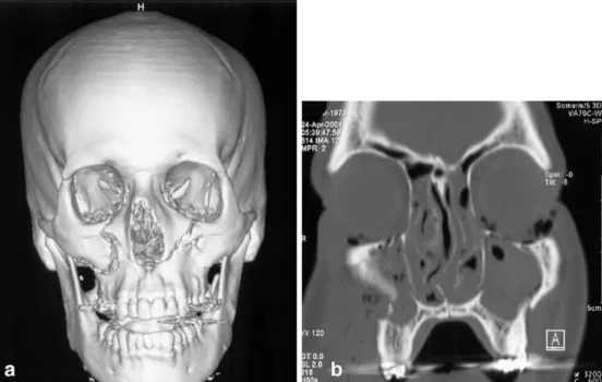
LeFort II fractures (Fig. 2) are pyramidal-shaped frac-tures that separate the maxilla and nasal skeleton from the remainder of the midface. The fracture line crosses the medial orbital wall, orbital floor, infraorbital canal, facial wall (zygomaticoalveolar crest) of the maxillary sinus anteriorly and the pterygoid plates posteriorly. Variations in the course of fractures with regard to the maxilla, nasal bones, the anterior ethmoid, and vomer or perpendicular plate are readily displayed by coronal CT images.
Nasal fractures, depending on the severity and direction of the trauma, may be accompanied by a fracture or dis-location of the nasal septum with hematoma formation or conchal avulsion.
Nasoethmoid fractures are caused by a frontal impact resulting in posterior displacement of the nasal bone and frontal process of the maxilla with telescope-like deforma-tion and foreshortening of the anterior ethmoid. The lac-rimal bone and cribriform plate are frequently involved.
Lateral midface fractures consist of zygomatic bone and zygomatic arch fractures.
The most common fracture is the zygomatic bone or trimalar fracture. The fracture traverses the facial and infratemporal wall of the maxillary sinus, the infraorbital canal, orbital floor, and inferior orbital fissure. The lateral orbital wall is affected along the sphenozygomatic and frontozygomatic suture. The zygomatic arch is fractured as well. Impingement of the zygomatic arch on the coronoid process of the mandible may occur in isolated arch or zygomatic bone fractures leading to reduced mouth open-ing. The degree and direction of displacement in zygo-matic bone (trimalar) fractures and the multiplicity of
Fig. 2 Three-dimensional sur-face shaded display image. (a) LeFort II type fracture with a typical pyramidal-shaped fracture affecting the central midface and infraorbital rim. Coronal CT (b) depicts the interruption of the zygomat-icoalveolar arch and midface impaction on the right. Note the additional fracture along the LeFort I plane.
fragments is best delineated and appreciated on 3D surface shaded CT reconstructions (Figs. 3and4).
Combined centrolateral fractures
LeFort III fractures are combined central and lateral mid-face fractures (centrolateral fractures). The fracture results in separation of the midface from the skull base. The frac-ture involves the nasomaxillary sufrac-ture, and lamina papy-racea medially, the pterygoid plates and the superior orbital fissure and courses laterally to involve the sphenozygo-matic and frontozygosphenozygo-matic suture. CT is particularly impor-tant to recognize potential optic canal, cribriform plate, and ethmoid roof involvement. LeFort III fractures may extend into the lesser sphenoid wing or via the major wing into the middle cranial fossa. Intracranial temporopolar epidural hematomas due to a fracture of the ala major have to be particularly looked for. Complications of LeFort III frac-tures may consist of CSF rhinorrhea, and affect the optic canal and/or superior orbital fissure [16].
The zygomaticomaxillary fracture is a variation of the zygomatic bone fracture. The fracture includes the alveolar process of the maxilla, tuber maxillae, and the hard palate.
Due to its medial extension it is classified among the combined centrolateral fractures.
Orbital trauma
A direct trauma to the orbit may cause a blow-out fracture resulting in fracture of the orbital floor and—by definition —leaving the inferior orbital rim intact. Fat herniation through the orbital floor causes the radiographic sign of the“pending drop” on Waters view, and a concomitant air fluid level within the maxillary sinus is almost invariably present. Additionally, or rarely alternatively, the medial orbital wall may be displaced into the ethmoid resulting in the so-called “medial blow-out fracture.” In classical blow-out fractures, discrimination of the herniated tissue is preferentially achieved by MR [17]. Even though rare (13.3%), the inferior rectus muscle was found by MR to be herniated, twice as often as when depicted by CT. In the same study, CT examination of the orbit was the method of choice to confirm medial wall (66%) and lateral wall frac-tures (33.3%). Coronal images are best suited to rule out concomitant involvement of the orbital roof reported in 9.3% of patients [18] or orbital apex injury [16]. Medial Fig. 3 A 37-year-old male
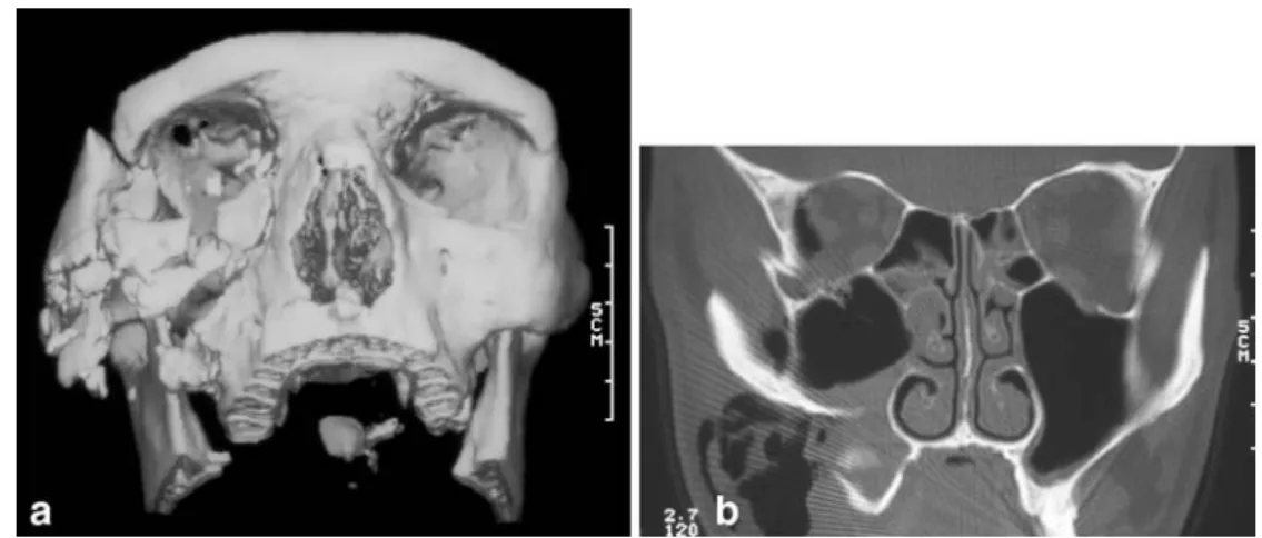
fol-lowing motor vehicle accident. Three-dimensional surface shaded display image (a) shows a comminuted zygomatic bone with multiple fragments and fractures following the zygo-maticomaxillary suture medially and the frontozygomatic suture superiorly. b Coronal CT scan confirms orbital involvement typical for a trimalar fracture with a fracture coursing through the sphenozygomatic suture lat-erally and the infraorbital canal. Note the discrepancy between a sole CT slice and the 3D image.
Fig. 4 a Three-dimensional surface shaded display image of a mildly displaced tripod frac-ture with involvement of the zygomaticomaxillary suture, the infraorbital rim, lateral orbital wall, and zygomatic arch. b The axial CT image reveals an additional mandibular fracture affecting the coronoid process caused by impingement of the zygomatic arch.
blow-out fractures with displacement of the lamina papy-racea and potential herniation of the medial rectus muscle are detected on coronal images as well. Axial bone window images are helpful to assess the entire anteroposterior ex-tension of impaction of the lamina papyracea.
Perforating injuries with foreign bodies are almost always detectable by CT. Size and density determine de-tectability. Attribution of the lesion to the intraocular or extraocular compartment is crucial. This may be difficult when the foreign body is close to the sclera [19]. On CT, careful (wide) window and level adjustment (the latter to negative values) are required in order not to miss wooden foreign bodies [20].
Complications Early complications of LeFort III fractures, nasoethmoid and orbital trauma are compression of the optic nerve due to a bone fragment, hematoma, or con-tusion. Traumatic optic neuropathy has been reported in 4% of patients [21]. Extension of the fracture into the superior orbital fissure may result in the so-called orbital apex injury leading to cranial nerve III to VI paralysis [16]. In LeFort II, trimalar and zygomatic fractures, the infraorbital nerve is frequently affected due to compromise by fragments that affect the nerve canal [22]. Retrobulbar emphysema (or hematoma) is readily depicted by CT and may be the cause of early exophthalmos. Decompression is indicated when vision declines.
Late complications become visible when the swelling subsides and posttraumatic enophthalmos develops due to a disparity between orbital contents and orbital volume. CT is required to delineate the cause of increased orbital volume which frequently consists of a combined effect of orbital floor defect, medial wall displacement, or insuf-ficient reposition of lateral wall fractures [23]. Traumatic involvement of the lacrimal sac and duct in LeFort II and nasoethmoid fractures may lead to postsaccal steno-sis. The osseous confines of the lacrimal sac and duct are well depicted either by plane CT or CT following dacryocystography.
Late complications like CSF rhinorrhea were evaluated in a study of 42 patients by noncontrast CT [24]. The au-thors advocate noncontrast high-resolution CT that depicted the site of CSF discharge in 30 cases (70%). Neither radio-nuclide nor CT cisternography produced positive results that were not previously visualized on noncontrast CT. However posttraumatic (pseudo-) meningocele or menin-gitis usually are assessed by MR imaging. MR is more sensitive to display dural defects, recognize inflammatory collections following meningitis, or distinguish brain con-cussion from abscess formation.
Transsphenoid basilar skull fractures (clival fractures)
The clivus is at the junction of the anterior, middle, and posterior cranial fossa. Clival fractures therefore may be associated with central midface, combined centrolateral midface fractures, or laterobasal fractures. Clival fractures are classified as transverse- and diagonal-type fractures [25]. Anterior and posterior transverse fractures pass between the pterygoid plates and sphenoid body and the sphenoid body and basilar portion of the occipital bone, respectively. Di-agonal fractures are extensions of mastoid or lateral frontal fractures. Clival fractures—the diagonal types in particular —signify a severe skull base trauma associated with a high mortality [25].
Complications Progressive exophthalmos, chemosis, and pulsation of the eye ball within days after skull base trauma point to a carotid cavernous sinus fistula (CCF) which drains into the orbit (Fig. 5). CCF occur in 0.2–0.3% of patients with skull base fractures but are significantly more common in patients with transverse basilar skull fractures [26]. The diagnosis of a CCF due to laceration of the wall of the internal carotid artery within the cavernous sinus may be established noninvasively by contrast-enhanced CT (Fig. 5a), or MRI and MRA. Digital subtraction angi-ography (Fig. 5b) is not required for diagnostic purposes
Fig. 5 A 22-year-old patient following head trauma 8 days previ-ously with progressive right exophthalmos and chemosis. a Axial contrast-enhanced CT displays a bone fragment of the lateral sphe-noid sinus wall that is rotated laterally impinging on the cavernous
sinus. The cavernous sinus is markedly dilated. b The lateral pro-jection of right carotid angiogram displays a carotid cavernous sinus fistula draining anteriorly into the superior ophthalmic vein.
but to perform occlusion of the fistulous communication by either balloon or coil embolization. A vessel injury is estimated to occur in 10% of patients in whom the fracture affects the cavernous or petrous carotid artery [27].
Laterobasal (temporal bone) fractures
Imaging Temporal bone trauma usually results from blunt head injury. Temporal bone fractures are indirect (burst) fractures that result from forces directed to the skull from laterally or anteroposteriorly. The resulting fracture occurs parallel to the long axis of the petrous bone in case of lateral impact, or perpendicular to the long axis when a frontal or occipital impact prevails.
High-resolution CT with thin collimation (0.5–0.75 mm) is the imaging technique of choice to assess temporal bone involvement in head trauma. Conventional images do not play a role in temporal bone trauma. The CT volume data set is calculated into thin overlapping slices that serve to obtain MPR images in the axial and coronal plane. The axial plane is angulated along the tympanic segment of the facial nerve; coronal images are oriented perpendicular. Bone window
algorithm images are crucial to recognize the fracture and define its course. CT images have to be scrutinized for in-volvement of the labyrinth, internal auditory canal, the facial nerve canal, and ossicular chain (Fig.6a). MR im-aging is performed to assess acute facial nerve palsy or sensoneural hearing loss. T1-weighted noncontrast images are mandatory to delineate a hematoma either intracochlear or perineural (Fig.6b). Heavily T2- weighted 3D fast spin echo sequences provide high-resolution images of the labyrinth and the intrameatal and labyrinthine course of the facial nerve.
Classification Classification of petrous bone fractures into longitudinal and transverse fractures relies on clinical findings and confirmation by CT and/or MR.
The longitudinal fracture runs parallel to the external auditory canal and courses through the antrum and epitym-panon where it may lead to interruption of the ossicular chain (Fig.6a). Even though the fracture is directed toward the geniculate ganglion, facial nerve injuries are rare (10– 20%), delayed, and often incomplete. CT displays con-siderable variation of the course of longitudinal fractures [10]. Longitudinal fractures that follow the anterior wall of Fig. 6 A 27-year-old patient with traumatic facial nerve paralysis
following head trauma. a Axial CT depicts a longitudinal petrous bone fracture with malleoincudal dislocation. A linear posterolater-ally rotated bone fragment of the anterior tegmen tympani is visualized immediately laterally to the geniculate ganglion. The
cor-responding axial T1W Gd-enhanced MR image (b) delineates the bone fragment in a slightly higher position just lateral to the tympanic segment of the facial nerve. Intraoperatively, compression of the nerve was found by the bone fragment and a hematoma.
Fig. 7 A 42-year-old female with hearing loss after a fall. a Axial CT depicts a transverse petrous bone fracture that ap-pears to spare the cochlea but courses through the cochlear aqueduct. The corresponding axial T1W Gd-enhanced MR image (b) shows marked con-trast uptake corresponding to a labyrinth prolapse probably resulting from rupture of Reissner’s membrane (noncon-trast T1 was normal).
the petrous bone may lead to defects of the tegmen tympani, while a posterior course may involve the facial nerve along the mastoid segment. Longitudinal fractures may extend through the sphenopetrosal synchondrosis to cross the clivus [25].
Transverse fractures constitute 10–30% of petrous bone fractures. Designation of the term“transverse” to a fracture requires a course of the fracture through the labyrinth either at the level of the vestibulum or by traversing the cochlea. A pneumolabyrinth may be noted. The fracture line may also pass through the internal auditory canal or cochlear aque-duct (Fig.7). According to this strict assignment of the label “transverse,” the remainder of fractures are termed “longi-tudinal” with either typical or modified course.
Complications Due to the sagittal oblique orientation of transverse fractures, involvement of the facial nerve is common. About 50% of patients display a facial nerve palsy which often is immediate and complete. The facial nerve is predominantly affected within the labyrinthine segment [28], contrary to the longitudinal type which tends to affect the proximal tympanic segment.
In cases of acute facial nerve palsy, MR may be performed supplementary to CT. MR may demonstrate a perineural hematoma [29], impingement by bone frag-ments (Fig.6a), or nerve transsection. T1 noncontrast and GD-enhanced images and heavily T2-weighted 3D ac-quisitions are required to recognize the cause and location
of facial nerve palsy. Enhancement along the intrameatal segment of the facial nerve was recognized in 92% of 22 patients with posttraumatic facial nerve paralysis. Further findings were labyrinthine hematoma; labyrinthine en-hancement following contrast administration in transverse fractures probably related to labyrinth prolapse (Fig. 7b). GD enhancement of the fracture line on high-resolution T1-weighted image renders the type and course of the petrous bone fracture (Figs. 6b and7b) visible as well.
Ossicular chain disruption is easily displayed by CT when it involves the malleoincudal articulation (Fig. 6a). Detection of incudostapedial derangement is more chal-lenging and requires parasagittal reconstructions or virtual endoscopic visualization of the ossicles.
Delayed complications of petrous bone fractures may consist of otogenic meningitis or abscess formation, pseu-domeningocele, and posttraumatic cholesteatoma. Radio-logic evaluation requires CT to assess the osseous confines of the petrous bone, while MR serves to distinguish intra-temporal soft tissue and adjacent brain involvement. Acknowledgements The author acknowledges the longstanding close collaboration with Prof. Klaus Graetz, head of the Department of Maxillofacial Surgery, with his interest in and support for dento-maxillofacial radiology; and, additionally, the cooperation of Dr Jorgo Stergiou, dentist and maxillofacial surgeon at the Department of Maxillofacial Surgery, with his continuous interest in radiologic clinical correlation.
References
1. Gassner R, Tuli T, Hächl O, Rudisch A, Ulmer H (2003) Cranio-maxillofacial trauma: a 10 year review of 9543 cases with 21067 injuries. J Craniomaxillofac Surg 31:51–61
2. Mathog RH (1984) Maxillofacial trau-ma. Williams and Wilkins, Baltimore 3. LeFort R (1901) Etude Experimental sur les fractures de la machoire super-ieure. Rev Chir Paris 23:208–227 4. Haug RH, Greenberg AM (1993)
Eti-ology, distribution and classification of fractures. In: Greenberg AM (ed) Cra-niomaxillofacial fractures: principles of internal fixation using the AO/ASIF technique. Springer Verlag, Berlin Heidelberg New York, pp 90–97; ch 2 5. Donat TL, Endress C, Mathog RH
(1998) Facial fracture classification according to skeletal support mech-anisms. Arch Otolaryngol Head Neck Surg 124:1306–1314
6. Rhea JT, Rao PM, Novelline RA (1999) Helical CT and three dimen-sional CT of facial and orbital injury. Radiol Clin North Am 37:489–513
7. Salvolini U (2002) Traumatic injuries: imaging of the facial injuries. Eur Radiol 12:1253–1261
8. Levy RA, Edwards WT, Meyer Jr et al (1992) Facial trauma and 3D recon-structive imaging: insufficiencies and correctives. Am J Neuroradiol 13:885– 892
9. Graetz K (1986) Eine neue Klassifika-tion zur Einteilung von Unterkiefer-frakturen. Dissertation, Basel 10. Ernst A, Herzog M, Seidl RO (2004)
Traumatologie des Kopf-Hals Bereichs. Thieme, Stuttgart
11. Assael LA (1993) Clinical aspects of imaging in maxillofacial trauma. Radiol Clin North Am 31:209–220
12. Chacon GE, Dawson KH, Myall RW et al (2003) A comparative study of 2 imaging techniques for the diagnosis of condylar fractures in children. J Oral Maxillofac Surg 61:668–673 13. Schuknecht B, Valavanis A (2003)
Osteomyelitis of the mandible. Neu-roimaging Clin N Am 13:605-618
14. Linnau KF, Stanley RBJ, Hallam DK, Gross JA, Mann F (2003) Imaging of high-energy midfacial trauma—what the surgeon needs to know. Eur J Radiol 48:17–23
15. Manson PN, Clark N, Robertson B et al (1999) Subunit principles in midface fractures: the importance of sagittal buttresses, soft tissue reductions, and sequencing treatment of segmental fractures. Plast Reconstr Surg 103:1287–1306
16. Linnau KF, Hallam DK, Lomoschitz FM, Mann FA (2003) Orbital apex injury: trauma at the junction between the face and the cranium. Eur J Radiol 48:5–16
17. Freund M, Hähnel S, Sartor K (2002) The value of magnetic resonance im-aging in the diagnosis of orbital floor fractures. Eur Radiol 12:1127–1133 18. Martello JY, Vasconez HC (1997)
Su-praorbital roof fractures: a formidable entity with which to contend. Ann Plast Surg 38(3):223–227
19. Kuhn F, Hulda T, Witherspoon CD et al (1996) Intraocular foreign bodies: myths and truths. Eur J Ophthalmol 6:464–471
20. Ho VT, McGuckin JF Jr, Smergel EM (1996) Intraorbital wooden foreign body: CT and MR appearance. Am J Neuroradiol 17:134
21. Levin LA, Beck RW, Joseph MP, Seiff S, Kraker R (1999) The treatment of traumatic optic neuropathy: the inter-national optic nerve trauma study. Ophthalmology 106:1268–1277 22. Zingg M, Laedrach K, Chen J et al
(1992) Classification and treatment of zygomatic fractures: a review of 1,025 cases. J Oral Maxillofac Surg 50 (8):778–790
23. Schuknecht B, Carls F, Valavanis A et al (1996) CT assessment of orbital volume in late posttraumatic enoph-thalmos. Neuroradiology 38:470–475 24. Stone JA, Castillo M, Neelon B,
Mukherji SK (1999) Evaluation of CSF leaks: high resolution CT compared with contrast-enhanced CT and radio-nuclide cisternography. Am J Neuro-radiol 20:706–712
25. West OC, Mirvis SE, Shanmuganathan K (1993) Transsphenoid basilar skull fractures: CT patterns. Radiology 188:329–338
26. Fabian TS, Woody J, Ciraulo DL et al (1999) Posttraumatic carotid cavernous fistula: frequency analysis of signs, symptoms, and disability outcomes after angiographic embolization. J Trauma 47:275–281
27. Resnick DK, Subach BR, Marion DW (1997) The significance of carotid canal involvement in basilar cranial fracture. Neurosurgery 40(6):1177–1181 28. Yeakley JW (1999) Temporal bone
fractures. Curr Probl Diagn Radiol 28:65–98
29. Sartoretti-Schefer S, Scherler M, Wichmann W, Valavanis A (1997) Contrast enhanced MR of the facial nerve in patients with posttraumatic peripheral facial nerve palsy. Am J Neuroradiol 18:1115–1125