HAL Id: hal-00558960
https://hal.archives-ouvertes.fr/hal-00558960
Submitted on 24 Jan 2011HAL is a multi-disciplinary open access archive for the deposit and dissemination of sci-entific research documents, whether they are pub-lished or not. The documents may come from teaching and research institutions in France or abroad, or from public or private research centers.
L’archive ouverte pluridisciplinaire HAL, est destinée au dépôt et à la diffusion de documents scientifiques de niveau recherche, publiés ou non, émanant des établissements d’enseignement et de recherche français ou étrangers, des laboratoires publics ou privés.
Gomez-Ramirez Ana, Pavel Kuzhir, Modesto Lopez-Lopez, Georges Bossis,
Alain Meunier, Durán Juan D.G.
To cite this version:
Gomez-Ramirez Ana, Pavel Kuzhir, Modesto Lopez-Lopez, Georges Bossis, Alain Meunier, et al.. Steady shear flow of magnetic fiber suspensions: theory and comparison with experiments. Journal of Rheology, American Institute of Physics, 2011, 55, pp.43. �10.1122/1.3523477�. �hal-00558960�
Steady shear flow of magnetic fiber suspensions: theory and comparison with experiments
A. Gómez-Ramírez1, P. Kuzhir2, M.T. López-López1, G. Bossis2, A. Meunier1, J.D.G. Durán2
1
Department of Applied Physics, University of Granada, Avda. Fuentenueva s/n, 18071, Granada, Spain
2
Laboratory of Condensed Matter Physics, University of Nice – Sophia Antipolis, Parc Valrose 06108 Nice Cedex 2 France
Synopsis
This paper is focused on the rheology of magnetic fiber suspensions in the presence of a magnetic field applied perpendicular to the flow. At low Mason numbers, Mn<0.1, the experimental flow curves show a steep initial section corresponding to the inclination and stretching of the gap-spanning aggregates formed upon magnetic field application. At higher Mason numbers, aggregates no longer stick to the walls and the flow curves reach a Bingham regime, with the dynamic yield stress growing with the magnetic field intensity. This yield stress appears to be about three times higher for the fiber suspensions than for the suspensions of spherical particles. Such difference, measured at relatively low magnetic field intensities, H0<30 kA/m, is explained in terms of the enhanced magnetic susceptibility of the aggregates
composed of fibers compared to the aggregates composed of spherical particles. For weak magnetic fields, the forces of solid friction between fibers are expected to play a minor role on the stress level of the suspension. In order to confirm these findings, we propose a new theoretical model, taking into account hydrodynamic interactions. The flow curve and the
yield stress predictions are in a good agreement with the experimental results for semi-diluted suspensions.
I. Introduction
Magnetorheological (MR) fluids are suspensions of magnetic particles, which can easily change their flow behavior upon application of an external magnetic field [Ginder (1998)]. Under a magnetic field, MR fluids develop a yield stress due to the internal structures formed by magnetic interaction between their constitutive particles. Depending on the shape and size of such particles, different types of structures appear in MR fluids, and consequently, the physical properties of these fluids, in particular their yield stress, depend strongly on the particle morphology. Helpful reviews on the properties and industrial applications of MR fluids are given by Ashour et al. (1996), Bossis et al. (2002), Carson et al. (1995), Jolly et al. (1998), Wang and Meng (2001).
During the last few years, new MR fluids made of magnetic micro- and nano-fibers have been developed, and stronger magnetic field-induced yield stresses [López-López et al. (2007, 2009), Bell et al. (2008, 2010), de Vicente et al. (2009), Gómez-Ramírez et al. (2009)] and a lower particle settling [Bell et al. (2007), Ngatu et al. (2008)] than in conventional MR fluids (made of spherical particles) have been reported. The same behavior has been observed for electrorheological (ER) fluids made of elongated particles [Kanu et al. (1998), Otsubo (1999), Kor and See (2010)]. The enhancement of the field-induced yield stress for MR fluids prepared with magnetic fibers has been recently explained as a consequence of the solid friction between fibers [Kuzhir et al. (2009)], which is much more important than in the case of micro-spheres. In this previous work, the authors considered a quasistatic regime of the shear deformation before the onset of the flow. The shear stress versus shear strain curves were calculated for different microstructures of the suspension and the yield stress was
attributed to the failure of the fiber network at a critical strain value. Another theoretical model for the calculations of the static yield stress and the storage modulus of magnetic fiber suspensions was proposed by de Vicente et al. (2009). These authors considered affine displacement of fibers under a strain applied, and the yield stress was calculated via the magnetic dipolar forces between fibers, which must be overcome in order to separate the particles. These theories predicted successfully the static yield stress at high magnetic fields but were not able to predict the flow curve of the suspension above the yield stress. The effect of the shear rate on the rheology of magnetic fiber suspensions was always modeled by a pure Bingham regime without consideration of an intermediate regime at low shear rate, which comes from viscous dissipation around elongated aggregates before their first rupture.
In the present work we have performed a careful investigation of the flow regime of magnetic fiber suspensions, which is important for the applications of the magnetic suspensions in smart hydraulic devices. The aim of the present study is to establish the effect of the shear rate on the microstructure and the rheology of the fiber suspension in the presence of a magnetic field. As in the case of the suspensions of spherical particles, we shall assume that, the fibers form elongated aggregates due to magnetic attraction between them, and the size and orientation of these aggregates in the shear flow will be defined by the equilibrium between the magnetic and the hydrodynamic torques and forces exerted on them [Martin and Anderson (1996)]. At high magnetic fields, we should also consider a solid friction between fibers within the aggregates. Such solid friction would enhance the mechanical strength of aggregates and increase the stress level in the suspension. However, for the sake of simplicity we shall neglect it and, as we shall see below, it is justified for the experimental conditions of the present study at high Mason numbers. An important feature of the present theory is that it includes the effect of the confinement of aggregates by the channel walls.
In order to check our theory, we have performed new measurements of the flow curves and compared experimental results to theoretical predictions. The measurements were done by increasing and subsequently decreasing shear stresses in order to check the hysteresis of the flow curves, which could appear due to the solid friction between fibers.
The paper is organized as follows. In the next section, we present the experimental procedure used in this work. The theory, including the microstructural model and the wall effects, is described in Section III. Both experimental and theoretical results on the microstructure and flow curves of the fiber suspension are discussed in section IV.
II. Experimental
The suspensions used in this work are constituted by cobalt micro-fibers dispersed in silicon
oil (Rhodorsil ®; VWR International, dynamic viscosity at 25 °C is η0=0.479 Pa·s). The
cobalt micro-fibers have been obtained by the polyol method [Fiévet (2000)], which in our case consists of the reduction of the cobalt ions by means of a mixture of polyol liquids (50% of ethylene glycol and 50% of diethylene glycol). The synthesis process and the magnetic and morphological characterization of the fibers are described in detail in López-López et al. (2007). The length and diameter of the fibers are 2l=37 ± 3 µm and 2a=4.9 ± 1.0 µm, respectively. So the mean fiber aspect ratio is l/a=7.6. The magnetization curve [Fig. 2 in López-López et al. (2009)] was fitted to a Fröhlich-Kennelly law [Jiles (1991)]:
M=χiMSH/(MS+χiH), with χi=70 – initial magnetic susceptibility of fibers and MS=1366±8
kA/m – the saturation magnetization.
In the present work, fiber suspensions containing two different volume fractions of cobalt particles (5% and 10%) were prepared as described in López-López et al. (2009). The evolution of the flow curves with the external magnetic field were studied in a steady-state
regime and compared with theoretical predictions for the suspensions mentioned above. The magnetorheological properties of the suspensions were measured using a Haake RS150 control stress rheometer in a plate-plate geometry, with the plate diameter being 35 mm and the gap between plates b=0.2 mm. A homogeneous magnetic field of intensity H0, ranging
from 0 to 30.6 kA/m, was generated by using a specially designed solenoid. The magnetic field was oriented perpendicular to the rheometer plates. The temperature in the rheometer gap was adjusted to 20°C and controlled by an external cooling system. Before the measurements, all the samples were subjected to mechanical and ultrasonic stirring during 5 minutes in order to ensure the required homogeneity. At the beginning of each experiment a pre-shear at shear rate 50s-1 was applied during 1 min. After that, the external magnetic field was applied and the sample was kept at rest during 1 min. Then, a stress cycle was applied to the suspensions: first, a growing stepwise stress ramp was applied from 0.1 Pa to some maximum value depending on the magnetic field intensity; then, the same procedure was repeated but decreasing the stress. The shear rate was measured at each step. In both cases, the duration of stress steps was sufficiently long to achieve a stable steady-state shear flow -shear rate fluctuations did not exceed five per cent of the mean value. The measurements at increasing and decreasing shear stress were carried out in order to check the possible hysteresis of the flow curves, which could be a manifestation of the solid friction between fibers.
III. Theory
III.-1 Microstructural model
Let us consider a simple shear flow of the fiber suspension between two infinite planes, with a
linear velocity profile vy =γz, like depicted in Fig.1a. An external magnetic field of intensity H0 is applied perpendicularly to the planes.
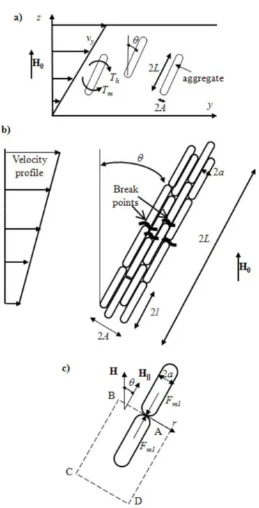
Fig. 1. Problem geometry for the microstructural model of the fiber suspension. A scheme of the shear flow is shown in part (a). Under a magnetic field applied, the fibers gather into aggregates, which displace with the flow without rotation. Their orientation is defined by the equilibrium of the magnetic torque, Tm and the
hydrodynamic torque, Th. A zoomed view of an aggregate is shown in part (b). Under tensile hydrodynamic
forces, the aggregate breaks near its central cross-section and the aggregate aspect ratio, L/A is defined by the equilibrium between the magnetic and the hydrodynamic forces. A sketch of the contact between two fibers inside an aggregate is shown in part (c). The magnetic force Fm1 acting between these two fibers is found by the
In order to find a rheological law of the fiber suspension under magnetic field, we introduce the following assumptions:
1. The fibers have a cylindrical shape and are characterized by a half-length l and a radius a. In the presence of field the fibers attract to each other and form elongated aggregates composed of numerous chains of fibers (Fig.1a). First, let us suppose that the aggregates have a cylindrical shape with half-length L and radius A. Then, let us assume that the fibers in the aggregates are all aligned parallel to each other and form therefore a closely packed bundle of cylindrical particles, as depicted in Fig. 1b. The internal volume fraction of such aggregates
can be estimated as the one for the 2D randomly packed bed of disks, Φa=π2/12 [Bideau et al.
(1983)].
2. The shear flow tends to orient these aggregates with the flow and the magnetic field tends to align them transversely to the flow. The aggregates are supposed to move affinely with the
flow without rotating. So, they are oriented at a certain angle, θ, in the y-z-plane with respect to the field direction (z-axis) and this angle is defined by the balance of the hydrodynamic and magnetic torques. Such balance is only possible when the chains of fibers lie in y-z-plane. This is consistent with the theory of Okagawa et al. (1974) who considered electrically polarized ellipsoidal particles in a shear flow. The authors of this paper showed that, in a steady state, the particles lie in a plane formed by the velocity vector and the electric (magnetic) field vector (y-z-plane in our case). The assumption of non-rotation of aggregates will be checked at the end of this subsection.
3. The magnetic field induces the growth of the aggregates and the shear flow tends to break them. So, the aggregate length is defined by the balance between the hydrodynamic tensile force and the magnetic attractive force, both exerted on the aggregate (Fig. 1b). This description have been used in many calculations of the rheological properties of conventional
MR fluids composed of spherical particles [Shulman and Kordinsky (1982); Martin and Anderson (1996); Volkova (1998); Kuzhir et al. (2003)].
4. At this stage, we will not take into account collisions, contacts and hydrodynamic interactions between aggregates. Strictly speaking, this assumption is verified for diluted fiber
suspensions with a volume fraction, Φ <( / )A L 2.Our theory predicts that the ratio A/L varies with shear rate in the range 0.02<A/L<0.13 upon the highest magnetic field intensity used in our work, H0=30.6 kA/m. Thus, 0.004<(A/L)2<0.017. Therefore, even with the 5 vol.%
suspension used in our experiments, we cover a semi-dilute regime, 2
( / )A L Φ ( / )A L , and
even a concentrated regime, Φ>A/L. However, theories of Batchelor (1971) and Shaqfeh and Frederikson (1990) show that the hydrodynamic interactions between non-Brownian fibers do not give a significant contribution to the viscosity of semi-diluted suspensions and the expressions derived for the shear stress in the dilute regime can be applied safely, at least, for the semi-dilute regime. Furthermore, the magnetic field has an alignment effect on the fiber aggregates, so they have less chance to collide with another one than in the case of isotropic orientation. This restricts the number of hydrodynamic interactions and mechanical contacts between aggregates. Consequently, the dilute fiber suspension theory could be a reasonable approximation even for more concentrated magnetic suspensions. Nevertheless, we shall see that the dilute limit approximation no longer works for a 10 vol.% fiber concentration.
5. The magnetic interactions between aggregates are taken into account through the Maxwell-Garnet mean field theory [Maxwell-Garnet (1922); Berthier (1993)]. According to this theory, the aggregates are immersed into an effective medium and subjected to the mean magnetic field H, averaged over the whole suspension. The surrounding aggregates modify the magnetic field in the proximity of a given aggregate, and create the so-called local field, HL, which is higher than the mean field H and accounts for the short-range magnetic
interactions. This local field magnetizes the aggregates such that their magnetic moment, m, depends on HL rather than on H. The magnetic torque acting on each aggregate is the vector
product of the magnetic moment of the aggregate and the mean field: Tm= ×m H . Using the Maxwell-Garnet theory we arrive to the following expression for the absolute value of the magnetic torque (see Appendix 1):
2 2 0 (1 ) sin cos 2 (1 ) f m a a f T χ μ H θ θ V χ − Φ = Φ ⋅ + − Φ (1)
Here, μ0=4π·10-7 H/m is the magnetic permeability of vacuum, Va=2πA2L is the aggregate
volume, χf is the magnetic susceptibility of a single fiber. In experiments, fibers from
nonlinear magnetic material were used, so the fiber magnetic susceptibility is supposed to be a function of the magnetic field inside the fiber Hf (see Appendix 1). The magnetic fields, H, HL
and Hf are functions of the external magnetic field H0, orientation angle, θ, and the volume
fraction Φ of the suspension. Their calculations are summarized in Appendix 1.
6. The magnetic torque acting on the aggregate is balanced by the hydrodynamic torque, which is found using the slender body theory of Batchelor (1970) for the dilute regime:
3 2 0 8 cos 3ln(2 / ) h L f T L A π ⊥ η γ θ = (2)
with η0 being the solvent viscosity of the fiber suspension, f⊥= +(1 0.64 ) /(1 0.5 )ε − ε a
non-dimensional coefficient, and ε =ln (2 / )−1 L A .
7. Under shear, the aggregates are subjected to tensile hydrodynamic forces, which break them in their weakest point. Thus, the aggregates are expected to break in their central transverse section, where hydrodynamic tensile forces are maximal (Fig. 1b). The following
expression is derived for the hydrodynamic tensile force acting on a half of the aggregate and tending to break it in the middle point:
2 2 0 sin cos ln(2 / ) h L f F L A π η γ θ θ = (3) with f2 = +(1 0.5 ) /(1 1.5 )ε − ε .
8. The breaking of the aggregate corresponds to the rupture of numerous bonds between neighboring fibers (Fig. 1b). Therefore, the maximal cohesive force of the aggregate is simply the sum of the magnetic forces acting between each contacting fiber. First, we must calculate the attraction force between two contacting fiber. It is estimated using the approach of Ginder and coworkers [Ginder and Davis (1994); Ginder et al. (1996); Bossis et al. (2002)]. Let us consider two fibers inside the aggregate, which touch each other by their ends. The surrounding fibers are replaced by an effective medium with a longitudinal component of the
magnetic field intensity, H =Hcos
θ
. Both considered fibers are supposed to be spherocylinders, and a part of the fiber volume in the vicinity of the contact point between fibers is supposed to be magnetized up to saturation magnetization, MS>>H. FollowingGinder’s theory, we calculate first the magnetic field distribution, Hg, in the gap between two
fibers, and then the magnetic force between fibers. This force comes from the integration of the Maxwell stress tensor over a closed contour ABCD (Fig. 1c), so that the final expression reads:
(
2 2)
2 2 2 0 1 0 0 0 2 ( ) 2 cos ( ) 2 a m g S F = π∫
μ H r −H rdr= πμ M Ha θ+O μ H (4)Here r is the radial coordinate (Fig. 1c), Hg =Hgcosθ is the component of the magnetic field Hg, parallel to the fiber axis. The force between two fibers touching each other
end-by-end appears to be the same as for two touching spherical particles [Bossis et al. (2002)], if we neglect the term of the order of µ0H2. This is because, for particles with high magnetic
permeability, the magnetic field Hg in the gap between particles depends on the particle
geometry in the vicinity of the contact point rather than on the geometry of the whole particle. The total cohesive magnetic force is simply the product of the force Fm1 and the number, N,
of interfiber contacts that are ruptured when the aggregate breaks under hydrodynamic forces:
1
m m
F = ⋅N F . This number of contacts is estimated as N ≈( / )A a 2Φ , so the final expression a for the magnetic force reads:
2 2
0
2 cos
m a S
F ≈ Φπ μ M HA θ (5)
The orientation angle of the aggregates and their aspect ratio, L/A, are found simultaneously from the equality of the hydrodynamic and magnetic torques [Eqs. (1) and (2)] and of the hydrodynamic and magnetic forces [Eqs. (3) and (5)]:
2 2 2 2 (1 ) 8 tan 3 (1 ) f S f M f H f χ θ χ ⊥ + − Φ = − Φ (6) 1/ 2 2 3/ 2 1/ 2 2 0 0 2 (1 ) ( / ) 3 1 ln(2 / ) 2 2 (1 ) f S a f H M L A L A f f χ μ η γ χ ⊥ ⎛ − Φ ⎞ = Φ ⎜⎜ ⋅ ⎟⎟ + − Φ ⎝ ⎠ (7)
Equation (7) defines the aggregate length from the balance between the magnetic attractive force and the hydrodynamic tensile force. Such static mechanical equilibrium is not strictly satisfied in dynamic conditions, when the aggregates are continuously formed and destroyed under the flow. Thus, shorter or longer aggregates than the ones predicted by Equation (7) could appear and exist during a certain amount of time depending on the aggregation/disaggregation velocity. At this stage, we suppose that all the aggregates have the same length, given by Equation (7). When the shear rate grows the aggregates become
shorter. At some critical shear rate, the last doublets of fibers disappear and the suspension contains only isolated fibers with a fixed aspect ratio, l/a. In this case, the fibers’ orientation is defined only by the torque balance [Eqs. (1), (2)]:
2 0 2 2 0 2 (1 ) 4 ( / ) tan 3 ln(2 / ) (1 ) f f l a f l a H χ η γ θ μ χ ⊥ + − Φ = − Φ (8)
As seen from Eq. (7), the aggregate length depends on the ratio, η γ μ0 / 0H3/ 2MS1/ 2 of hydrodynamic to magnetic forces, called Mason number. The transition between the aggregated state and the non-aggregated one (isolated fibers) happens at the critical Mason number obtained by replacing L by the fiber length, l, in Eq.(7)
1/ 2 2 0 1 3/ 2 1/ 2 2 0 2 (1 ) ln(2 / ) 3 1 ( / ) 2 2 (1 ) f c a S f l a Mn H M l a f f χ η γ μ χ ⊥ ⎛ − Φ ⎞ ≡ = Φ ⎜⎜ ⋅ ⎟⎟ + − Φ ⎝ ⎠ (9)
We shall now calculate the shear stress in our suspension. The most general expression for the stress tensor in a suspension of non-spherical force-free particles subject to an external torque was given by Pokrovskiy (1978). We assimilate our chains of fibers with high-aspect ratio particles, for which the stress tensor takes the following form:
0 0 1 2 4 3 1 1 2 2 ik ik ik ik i k l m ik l m lm a i l lk k l li ik a a p e e e e e e e e T e e T T V τ = − δ + η γ + Φ η ⎨⎧ γ +α⎢⎡ − δ ⎤⎥γ ⎫⎬+ Φ ⎩ ⎣ ⎦ ⎭ Φ ⎧ ⎡ ⎤ ⎫ + ⎨ ⎣ + ⎦− ⎬ Φ ⎩ ⎭ (10)
Here, p is the pressure, δik is Kronecker delta, γik =1/ 2(∂ ∂ + ∂vi/ xk vk/∂ is the rate-of-xi)
strain tensor, α is the dimensionless friction factor, which can be found using the slender body theory [Batchelor (1970); Kim and Karrila (1991)]:
2 1 2 ( / ) 3 ln(2 / ) L A f L A α= , with
1 (1 0.64 ) /(1 1.5 )
f = +
ε
−ε
and ε =ln (2 / )−1 L A ; Tik is the tensor of the magnetic torque
applied to the aggregates; ei is the projection of the unit vector e onto the ith axis; the vector e
is collinear with the longitudinal axis of symmetry of the aggregate and has the following
components in the Cartesian system x,y,z: e=(0,sin , cos )θ θ . The factor Φ/Φa stands for the
volume fraction of porous aggregates, each having a volume fraction of fibers, Φa. The angle
brackets denote the averaging over the orientation of aggregates. Since all the aggregates are
supposed to have the same orientation characterized by the angle θ, we do not need to perform such averaging. Applying the last equation to the simple shear flow considered in
Fig.1a, and taking into account that the shear rate is γ =dvy /dz, we get the following expression for the shear stress (yz-component of the stress tensor):
2
2 2 2
0 0 1
2 ( / )
2 sin cos cos
3 ln(2 / ) m a a a L A f T L A V τ η γ= + Φ η γ ⎧⎨ + θ θ⎫⎬+ Φ θ Φ ⎩ ⎭ Φ (11)
Replacing the magnetic torque by Eq. (1) and using Eq. (7) for the chain aspect ratio, we get the final expression for the shear stress for the aggregated state of the suspension (formula (12)). For the disaggregated state we replace in Eq. (11) L by the length l of the fibers and A by the fiber radius a, which leads to Eq. (13):
1/ 2 2 2 2 1 2 2 0 0 2 2 3 2 1 (1 ) 2 ( ) 1 2 sin cos 3 2 (1 ) (1 ) sin cos , 2 (1 ) f S a f f c c f M f H H f f Mn Mn Mn χ τ η γ μ θ θ χ χ θ θ χ ⊥ ⎧⎛ − Φ ⎞ ⎛ Φ ⎞ ⎪ = ⎜ + Φ ⎟+ Φ ⎨⎜⎜ + − Φ ⎟⎟ + ⎝ ⎠ ⎪⎝⎩ ⎠ ⎫ − Φ ⎪ + ⎬ ≤ ≤ + − Φ ⎪⎭ (12) 2 2 2 2 2 3 0 0 1 0 1 (1 ) 2 ( / )
2 sin cos sin cos ,
3 ln(2 / ) 2 (1 ) f c f l a f H Mn Mn l a χ τ η γ η γ θ θ μ θ θ χ − Φ ⎧ ⎫ = + Φ ⎨ + ⎬+ Φ > + − Φ ⎩ ⎭ (13)
Here Mnc2 is the highest Mason number for which the aggregates span the gap of the cell and
is obtained by replacing in Eq. (9) the length of a fiber by the maximum length authorized by the presence of the walls as we shall see in the next section. Eq. (12) corresponds to the
aggregated state and the orientation angle, θ, is found from Eq. (6). Eq. (13) corresponds to high shear rates, where all the fibers are isolated and the orientation angle should be replaced by the one found from Eq. (8). Note that at zero shear rate, the shear stress given by Eq. (12) does not vanish and the fiber suspension behaves approximately as a Bingham fluid:
Y
τ τ ηγ= + with a plastic viscosity η η= 0(1 2+ Φ Φ and a yield stress given by the last / a) term of Eq. (12): 1/ 2 2 2 2 2 2 3 0 (1 ) (1 ) 2
sin cos sin cos
3 2 (1 ) 2 (1 ) f f S Y f f M H H χ χ τ μ θ θ θ θ χ χ ⎧⎛ − Φ ⎞ − Φ ⎫ ⎪ ⎪ = Φ ⎨⎜⎜ ⎟⎟ + ⎬ + − Φ + − Φ ⎪⎝ ⎠ ⎪ ⎩ ⎭ (14)
The second term in Eq. (14) is exactly the one obtained by the derivation of the magnetic energy versus the strain [Bossis et al. (1997)], but the first term is more subtle since it comes from the fracture of aggregates when the hydrodynamic force overcomes the magnetic one. In
this equation we have omitted the factor (f1) /(2 f f⊥ 2 ) because, in the limit of zero shear
rate, the aggregates become infinitely long and each numerical factor f1, f2 ,f⊥ tends to
unity according to Batchelor (1970).
The yield stress appears to be proportional to the fiber volume fraction, Φ, and to the term
μ0H2, like in the case of a conventional MR fluid composed of spherical particles. Note also
that with the decrease of the shear rate, the aggregate length increases roughly as γ−1/ 2and becomes infinite at zero shear rate. In reality, the chains are bounded by the channel walls, so they have a finite length and can interact with the walls. Thus, formulas (6), (7) and (12) should be applied only in the domain of the shear rates wherein the chains do not span the gap
between the planes and do not interact with them, that is to say for Mason numbers larger than Mnc2.
All these results were derived under the assumption of non-rotating aggregates. In reality, the aggregates do not rotate only at relatively low shear rates and at magnetic fields strong enough to maintain the orientation of aggregates fixed. A critical Mason number corresponding to the onset of rotation is estimated using the results of the work of Okagawa et al. (1974). For the disaggregated state the expression for this critical Mason number reads:
1/ 2 2 (1 ) 3ln(2 / ) 8( / ) 2 (1 ) f rotation f S l a H Mn l a f M χ χ ⊥ − Φ ⎛ ⎞ ≈ ⎜ ⎟ + − Φ ⎝ ⎠ (15)
In the ranges of shear rates and magnetic fields used in our experiments, the Mason number remains below the critical value Mnrotation, except at zero magnetic field. So the assumption of
non-rotation is justified.
Note that our microstructural model could be easily applied to the chain-like structure when, instead of forming thick aggregates, the fibers gather into single linear chains. The rheological behavior of such structure is described by the same formulas (6)-(15), in which the volume
fraction Φa=1, and the aggregate radius A should be replaced by the fiber radius a.
III-2 Wall effects
According to Eq. (7), at low shear rates and high magnetic fields so that the Mason number is smaller than Mnc2, the aggregates become very long and, therefore, they may span the gap
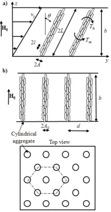
between the two planes (rheometer gap). Nevertheless, the aggregates cannot be infinitely long, since they are bounded by the gap width, b, as depicted in Fig. 2a. In this case, the orientation of the aggregates and the shear stress developed in the suspension will be different
from those found for unbounded shear flow. In this subsection we calculate these magnitudes taking into account wall effects.
Fig. 2. Aggregates confined by the walls. (a) – shear flow with confined aggregates. The aggregate length, 2L is bounded by the gap width, b. The aggregates are supposed to slide on the walls without solid friction. (b) – formation of a hexagonal array of cylindrical columns of fibers at rest (zero shear rate). The aggregate radius, A0 is defined by minimization of the suspension energy.
The aggregates could experience either a solid friction with the walls of the shear cell or hydrodynamic interactions with them. In our experiments, we did not observe a significant static yield stress of the fiber suspension in the magnetic field. In other words, the suspension started to flow at low applied shear stresses even though its viscosity was very high. This could be an argument for the smallness of the solid friction between aggregates and walls. The hydrodynamic interactions could come from the lubrication forces between the aggregate extremities and the walls. At first approximation, we shall neglect these interactions, so that the only wall effect will consist of the confinement of the aggregates by the walls. When the aggregates are inclined by the shear flow, they could be stretched by hydrodynamic tensile forces. On the other hand, the solid friction between fibers inside aggregates could hinder such extension. Comparing hydrodynamic forces [Eq. (3)] and friction forces, which are
approximated by ξTm/L [Kuzhir et al. (2009)], we can estimate the order of magnitude of the
critical Mason number below which the aggregates are not extensible:
1/ 2 2 2 (1 ) ln(2 / ) ( / ) 2 (1 ) f extension f S L A H Mn L A M χ ξ χ − Φ ⎛ ⎞ ∝ ⎜ ⎟ + − Φ ⎝ ⎠ , (16)
where ξ ∼0.3 is the interfiber friction coefficient. Estimations show that Mnextension<<Mnc2, so
the aggregates are extensible in the range of Mason numbers Mnextension<Mn<Mnc2. Since the
number Mnextension is small, we can assume, without loss of precision, that the aggregates are
extensible at any small Mason number, Mn<Mnc2. When they are inclined at an angle θ
relative to the magnetic field direction, they are stretched and continue to touch the walls but slide over the walls without friction (Fig.2a), such that their length is
/ 2 cos
As in the case of unbounded fiber suspensions, the orientation angle of the aggregate is defined by the balance of the magnetic torque (1) and the hydrodynamic torque (2). The
aggregate radius A appears in the expression for the angle θ. This radius is unknown and we shall estimate it using the following considerations.
Let us consider a static equilibrium state of the fiber suspension at zero applied shear stress, with the external magnetic field applied normally to the planes. In the absence of solid friction between fibers and between fibers and walls, the suspension will adopt a structure corresponding to the minimum of its energy. Such structure could be a series of cylindrical columns composed of densely packed fibers and extended over the gap between both planes (Fig. 2b). This kind of phase separation was proposed theoretically and confirmed experimentally for conventional MR fluids composed of spherical particles [Skjeltorp (1985), Wang et al. (1994), Grasselli et al. (1994)]. Minimization of the suspension energy gives us the radius A0 of the aggregates at rest, as a function of the applied magnetic field and of the
fiber magnetic properties. We perform this analysis in Appendix 2 using the methods described by Grasselli et al. (1994). When the suspension is sheared with a low shear rate (at low Mason numbers), the cylindrical aggregates are supposed to slip over the walls without
friction and to tilt at an angle θ from their static vertical position. We assume that the aggregate volume is conserved when the aggregates tilt, until they break under the tensile
hydrodynamic forces. The volume conservation of aggregates reads: πA2(2 )L =πA b02 . Taking into account Eq. (17), we find the radius of the cylindrical aggregate:
1/ 2 0cos
A= A θ. (18)
The suspension shear stress in the case of confined aggregates (where the aggregates span the gap of the shear cell) is defined by a formula similar to Eq. (11). The critical Mason number
corresponding to the transition between the states of confined and free aggregates is found by equating the length of a confined aggregate [Eq. (17)] to that of a free aggregate [Eq.(7)]. Below, the formulas for the orientation angle, aspect ratio, suspension shear stress and critical Mason number are summarized for the state of confined aggregates:
2 3/ 2 0 0 2 2 3/ 2 0 0 /(2 cos ) 2 (1 ) 1 4 tan 3ln /( cos ) (1 ) f a f b A f H b A θ η γ χ θ μ χ θ ⊥ ⎡ ⎤ + − Φ ⎣ ⎦ = Φ ⎡⎣ ⎤⎦ − Φ (19) 3/ 2 0 / /(2 cos ) L A=b A θ (20) 2 3/ 2 0 2 2 0 0 3/ 2 1 0 2 2 3 0 2 /(2 cos ) 2 2 sin cos 3 ln /( cos ) (1 ) sin cos , 2 (1 ) a f c f b A f b A H Mn Mn θ τ η γ η γ θ θ θ χ μ θ θ χ ⎧ ⎡ ⎤ ⎫ Φ ⎪ ⎣ ⎦ ⎪ = + ⎨ + ⎬+ Φ ⎪ ⎡⎣ ⎤⎦ ⎪ ⎩ ⎭ − Φ +Φ < + − Φ (21) 1/ 2 3/ 2 2 0 2 3/ 2 2 2 0 ln /( cos ) 3 (1 ) 1 2 2 (1 ) /(2 cos ) f c a f b A Mn f f b A θ χ χ θ ⊥ ⎡ ⎤ ⎛ − Φ ⎞ ⎣ ⎦ = Φ ⎜⎜ ⋅ ⎟⎟ + − Φ ⎡ ⎤ ⎝ ⎠ ⎣ ⎦ (22)
Note finally, that the series of equations (6) – (9), (12), (13), (19) – (22) defines completely the microstructure and rheology of the magnetic fiber suspensions at the three states considered above: aggregated state with confined aggregates (Mn<Mnc2), aggregated states
with free aggregates (Mnc2 ≤Mn≤Mnc1) and disaggregated state (Mn>Mnc1).
IV. Results and discussion
IV-1 Aggregate orientation and aspect ratio
Our theoretical model developed in Section III gives the orientation and the aspect ratio of the aggregates, as well as the macroscopic shear stress versus shear rate dependence. The
theoretical dependence of the aggregate orientation angle on the shear rate is shown in Fig. 3 at three different values of the external magnetic field.
Fig.3. Orientation angle of the aggregates as a function of the shear rate. Curves 1, 2 and 3 correspond respectively to external magnetic fields of intensity H0= 6.11, 18.3, and 30.6 kA/m.
As seen in this figure, each curve has three distinct sections, corresponding to the three aggregation states of the suspension, and the slope of the curves changes drastically in the transition points between each state. At zero shear rate the orientation angle tends to zero, meaning that the aggregates are aligned with the magnetic field. When the shear rate increases from zero to the first critical point (Mason number Mn<Mnc2), the orientation angle increases
quite rapidly from zero up to 60-70º. This section of the curve corresponds to the aggregated state with confined aggregates, and the increase of the orientation angle corresponds to the inclination of the aggregates by the shear flow when they still span the rheometer gap (Fig. 2a). Above the first critical shear rate, the aggregates no longer resist to the tensile hydrodynamic forces and are progressively broken by the increasing shear rate. This corresponds to the state of free aggregates (aggregates not limited by the rheometer plates), at
Mason numbers, Mnc2≤Mn≤Mnc1. Such state is represented by the middle plateau of the curve θ = f( )γ , where the angle θ depends only weakly on the shear rate. In fact, the
orientation angle is an increasing function of both the shear rate γ and the aggregate length L, namely, tanθ∝L2γ . On the other hand, according to Eq. (7), the aggregate length decreases with the shear rate as L2∝1/γ , and thus the orientation angle θ should be independent of the shear rate. In reality, the shear rate does not appear directly in Eq. (6) for the angle θ, but it intervenes implicitly through the numerical factors f⊥ and f , which are nonlinear functions 2
of the aggregate length L, which depends, in its turn, on the shear rate [Eq. (7)]. When the shear rate overcomes the second critical value (Mason numbers Mn>Mnc1), all the aggregates
are destroyed and the suspension consists of isolated fibers (disaggregated state). The fiber orientation angle increases again with the shear rate accordingly to Eq. (8). At very high shear rates or high Mason numbers, the hydrodynamic forces become very important compared to the magnetic ones, and the fibers tend to be aligned with the flow, so that their orientation angle approaches asymptotically to 900. Notice that, at a fixed shear rate, the orientation angle is a decreasing function of the magnetic field, which is consistent with the fact that a higher magnetic field induces a stronger alignment of the fibers in the field direction.
The theoretical dependence of the aggregate aspect ratio normalized by the fiber aspect ratio,
( / ) /( / )L A l a on the shear rate is presented in Fig. 4.
Fig.4. Relative aspect ratio of the aggregates (normalized by the aspect ratio of fibers) as a function of the shear rate. Curves 1, 2 and 3 correspond respectively to H0= 6.11, 18.3 and 30.6 kA/m.
The three different aggregation states of the suspension are also distinguished in these curves. The zone of the confined aggregates corresponds to the increasing part of the curves
( / ) /( / )L A l a = f( )γ . Such increase of the aggregate aspect ratio with the shear rate comes from the extension of the aggregates when they are inclined by the shear flow, but still span the gap between the rheometer plates (Fig. 2a). While approaching to zero shear rate, the aggregates become perpendicular to the plates and their aspect ratio tends to a constant value equal to the gap width divided by the aggregate diameter, b/(2A0). This value depends on the
field (but almost negligibly) through the aggregate radius, A0, which is found in Appendix 2
by minimization of the suspension free energy. At Mnc2≤Mn≤Mnc1, the aggregates do not longer span the gap and their aspect ratio decreases with the shear rate, roughly proportional
to γ−1/ 2. At Mn>Mn
c1, we arrive to the disaggregated state of the suspension, and the curves
for different magnetic fields collapse into a single horizontal curve with ( / ) /( / ) 1L A l a = , that corresponds to isolated fibers with the fixed aspect ratio, l/a. As seen in Fig. 4, in the region of confined aggregates (Mn<Mnc2), the aggregate aspect ratio decreases with increasing the
magnetic field at fixed shear rate. This comes from the fact that, at higher magnetic fields, the
aggregates are subject to a higher magnetic torque, which reduces the orientation angle θ. In this way, the aggregate length, which is bounded by the channel gap, and is thus equal to
L=b/cosθ, also decreases with the field. In the domain of free aggregates, their length is defined by the balance between the hydrodynamic and the magnetic forces. So, at higher magnetic fields the cohesive magnetic forces between particles are stronger and the aggregates resist better to the tensile hydrodynamic forces. This explains that, in the domain
of free aggregates (Mnc2≤Mn≤Mnc1), the aggregate aspect ratio increases with the magnetic field.
In order to compare the experimental flow curves with the theoretical ones, it is important to remark that, in plate-plate experimental geometry, the measured shear stress is not a real stress developed by the suspension but an apparent stress, which is related to the friction
torque experienced by the rotating plate. The apparent shear stress, τa is related to the real
shear stress, τ, by the Mooney formula [Macosco, (1994)]:
2 3 0 4 R a R d γ τ γ τ γ γ =
∫
, (23)where γR is the shear rate at the MR sample edge.
The theoretical and experimental dependencies of the apparent shear stress on the shear rate are shown in Fig. 5 for the fiber suspension containing 5 vol.% of particles.
Fig.5. Flow curves for a fiber suspension with Φ=0.05 in the presence of a magnetic field. Lines correspond to the theory; the symbols correspond to experimental data obtained using a controlled-stress rheometer. Full and open symbols stand respectively for increasing and decreasing shear stress. Both theoretical and experimental curves correspond to magnetic fields of intensity H0, from bottom to top: 0, 6.11, 12.2, 18.3, 24.4 and 30.6 kA/m. The inset shows the same flow curves at low shear rates.
We see that, both in experiments and in theory, the flow curves have two straight sections with different slopes, the left one with a steep slope and the right one with a less steep slope. Let us consider each part separately.
The left part of the flow curve corresponds to the state of confined aggregates. The aspect ratio of the aggregates is very high and they span the rheometer gap. Therefore they offer a high hydraulic resistance to the flow, which could explain the steepness of this part of the curves, corresponding to a high apparent viscosity at low shear rates. The theoretical initial slope of the flow curves can be easily found from Eqs. (19), (21). Neglecting the term on
sin2(θ) in Eq. (21) at low shear rates, the expression for the initial slope reads:
[
]
[
]
2 0 0 0 0 /(2 ) 4 ( / ) 1 2 3 ln / a b A f b A γ τ γ η ⊥ → ⎧ Φ ⎛ ⎞⎫ ⎪ ⎜ ⎟⎪ = ⎨ + ⎜ + ⎟⎬ Φ ⎪ ⎝ ⎠⎪ ⎩ ⎭ (24)In the limit of small shear rates, the slopes of all the theoretical curves are the same and do not depend on the magnetic field intensity, but they depend on the initial aspect ratio of aggregates, b/(2A0). For the fiber suspension with 5% volume fraction, the initial slope
predicted by Equation (24) is equal to 13η0, which is 12 times the final slope corresponding to
high shear rates. As we can see in the inset of Fig. 5, our theoretical model underestimates the initial slope of the flow curve. This is probably because we have neglected hydrodynamic interactions between the aggregates and the walls. Another important point is that, in experiments, we observe a relatively small static yield stress – the real threshold stress at zero shear rate, corresponding to the failure of the suspension structure and to the flow onset. It is, at least, one order of magnitude lower than the dynamic yield stress. Recall that we carried out our rheological measurements in a controlled-stress mode, which allows measuring the static yield stress. The smallness of the static yield stress could be understood by a poor
adhesion of the aggregates to the rheometer plates, made of titanium with a roughness around 1 micron. So, when the suspension is sheared, the aggregates are supposed to slide on the plates with only a low solid friction, which probably gives a negligible contribution to the shear stress. Under the assumption of the absence of solid friction, our theory predicts zero shear stress at zero shear rate. In fact, in the limit of zero shear rate, the aggregates are strictly
aligned with the field (θ=0), so the shear stress vanishes since the magnetic torque acting on the aggregates is zero.
The rounded part of the flow curves corresponds to the transition between the regime of confined aggregates to that of free aggregates, which happens at Mason number Mnc2
[Eq.(22)]. Note that the shear rate in the rheometer gap increases linearly with the radial
distance from zero on the disk axis to a maximal value, γR at the disk edge. So, depending on the position in the gap, the zone of confined aggregates can coexist with the zone of free aggregates, and the transition between both regimes happens smoothly with increasing the
shear rate γR, which explains the rounded shape of the transition zone. Note that in the hypothetical case of the shear rate being constant throughout the gap, we should observe a sharp transition between both regimes.
Starting from a shear rate γ ≈50 s-1, the experimental and theoretical curves become linear and almost parallel to each other, which corresponds to the Bingham rheological law, τ τ ηγ= +Y , with τY being the dynamic yield stress and η the plastic viscosity. Recall that this dynamic
yield stress is defined as a linear extrapolation of the flow curve to zero shear rate. We observe a reasonable quantitative correspondence between the theoretical and the
experimental flow curves at γ >50 s-1, without introducing any adjustable parameter. The Bingham behavior observed experimentally is well predicted by our theory. In our theory, the
stress τY contains the hydrodynamic part, which is proportional to ( / )L A 2η γ0 and the magnetic part, which does not depend on γ. As stated above, the aggregate length appears to be inversely proportional to γ1/ 2, thus, the hydrodynamic part of the stress τ
Y and,
consequently, the stress τY itself do not depend on the shear rate. So, in our model, this stress
is assigned to the dynamic yield stress. Notice that, in both the theoretical and the experimental flow curves, the regime of isolated fibers is not distinguished from the regime of free aggregates. This is because the considered transition happens at relatively high shear rates (Mason numbers Mnc1), when the magnetic field does not play any significant role on
the shear stress. Thus, in both regimes, the aggregates or isolated fibers appear to be almost aligned with the flow and, according to Eqs. (11), (12), the slope of the curves corresponding
to these two regimes is equal to η0(1 2+ Φ Φ and / a) η0(1 2 )+ Φ , respectively, so it is nearly the same.
Notice finally, that the experimental flow curves have a small hysteresis, which could come from the solid friction between fibers. Nevertheless, the smallness of this hysteresis could mean that the hydrodynamic forces dominate over the forces of solid friction, at least, for
semi-dilute suspensions (Φ<0.05) and at Mason numbers Mn>0.01.
The experimental and theoretical flow curves for the most concentrated suspension (Φ=0.1) are shown in Fig.6. The calculated shear stress does not include the regime of the confined aggregates, so the theoretical flow curves do not start from the origin but they cross the ordinate axis at a positive shear stress – dynamic yield stress. As can be seen in this figure, the theoretical plastic viscosity is much lower than the experimental one. This is probably because of the existence of strong hydrodynamic interactions between the aggregates, which have not been taken into account in our theory. If we compare simple analytic expressions for
dilute suspensions [Batchelor (1971)], with those for semi-dilute suspensions where hydrodynamic screening is taken into account [Shaqfeh and Fredrickson (1990)], it appears that the role of the hydrodynamic interactions between aligned fibers cannot be neglected
above Φ=0.05. Nevertheless, this could not explain the large difference between our experiments and theory for Φ=0.1. In order to explain this discrepancy, collisions between aggregates and, especially, energy dissipation due to lubrication forces should be taken into account, in the same way as it was done for concentrated suspensions of non-magnetic fibers [Toll and Manson (1994); Petrich and Koch (1998); Servais et al. (1999); Schmid and Klingenberg (2000); Moghamaddam and Toll (1995); Linddstrom and Uesaka (2007); Férec et al. (2009)]. In perspective, we shall try to incorporate such interactions into our theory to improve the rheological predictions for concentrated magnetic fiber suspensions.
Fig.6. Flow curves of a suspension containing 10 vol.% of magnetic fibers in the presence of magnetic fields. Full symbols: experiments for increasing shear stress; open symbols: experiments for decreasing shear stress. Applied magnetic field intensity, H0, was (from the down to the upper curve): 0, 6.11, 12.2, 18.3, 24.4 and 30.6 kA/m.
Interestingly, in experiments with the most concentrated suspension (Φ=0.1) we do not observe any significant hysteresis of the flow curves. This could signify that the effect of the
solid friction between fibers is low compared to the viscous friction and to the magnetic torque effect, at Mason numbers Mn>0.01.
The dependence of the apparent dynamic yield stress on the magnetic field intensity for the fiber suspension containing 10 vol.% of particles is shown in Fig.7. At zero magnetic field, the dynamic yield stress is non-zero, being about 10% of the dynamic yield stress at a magnetic field intensity H0=30.6 kA/m. Such non-negligible yield stress in the absence of
magnetic field could come from the solid friction between fibers in a concentrated regime at low shear rates. The appearance of solid friction at low shear rates should not be contradictory to the smallness of the flow curve hysteresis. In fact, at low shear rates, the viscous friction is expected to be small compared to the solid friction that induces the yield stress. At higher shear rates, the viscous friction becomes dominant, dry contacts between aggregates are supposed to disappear, and the flow curves show a good reversibility. Since we have not included any solid friction in our theory, it predicts a zero yield stress at zero magnetic field.
Fig.7. Apparent yield stress for a suspension containing 10 vol.% of cobalt fibers, as a function of the intensity of the external magnetic field. In the inset of the figure, the yield stress increment, τ τY − Y0, is shown as a function of the magnetic field intensity. Points stand for experiments, solid lines for theory.
In any case, in both theory and experiment, the magnetic field effect on the suspension
rheology is characterized by the increment, τ τY − Y0, of the yield stress in the presence of a magnetic field, rather than by the yield stress itself. Here, τY0 is the yield stress in the absence
of magnetic field. In order to compare experiments with theory, first, we convert the
theoretical yield stress (14) into the apparent yield stress, (τY)a. This is done using the Mooney
formula (23), which, after substituting τ=τY, gives (τY)a=4/3τY. In the inset of Fig. 7, we
compare the experimental and the theoretical results for the increment of the apparent yield
stress, (τ τY− Y0)a, and, actually, we obtain a fairly good correspondence. As already stated, this model is not appropriate for predictions of the suspension plastic viscosity (slope of the flow curves) in concentrated regime.
IV-3 Comparison between spheres and fibers
Let us now compare the rheology of suspensions of magnetic fibers with the rheology of suspensions of spherical particles, both made of the same material (cobalt) and at the same volume fraction 5(%). The dependencies of the apparent dynamic yield stress on the magnetic field intensity are shown in Fig.8 for both suspensions. In experiments, the dynamic yield stress of the suspension of fibers appears to be about three times higher than that of the suspension of spheres. Note that the magnetization of both spherical and fiber-like cobalt particles is similar, and both types of particles are micron-sized, so non-Brownian [López-López et al. (2007)]. Thus, the difference in the yield stress cannot be explained by different magnetic properties, neither by their Brownian motion. In order to explain such discrepancy, we can adapt our microstructural model (section III.1) to suspensions of spherical particles and, in this way, we obtain the following expression for the dynamic yield stress of suspensions of spherical particles:
1/ 2
2 2
2 2 2 3
0
2 (1 / ) (1 / )
sin cos sin cos
3 2 (1 / ) 2 (1 / ) S a a a a a Y a a a a a M H H χ χ τ μ θ θ θ θ χ χ ⎧⎛ − Φ Φ Φ ⎞ − Φ Φ ⎫ Φ ⎪ ⎪ = ⎨⎜ ⎟ + ⎬ Φ ⎪⎩⎝ + − Φ Φ ⎠ + − Φ Φ ⎪⎭(25)
Remember that the apparent dynamic yield stress is (τY)a=4/3τY. The angle θ in the last
formula is defined by the balance of the hydrodynamic and magnetic forces:
2 2 8 2 (1 / ) tan 3 (1 / ) S a a a a a M H χ θ χ + − Φ Φ = Φ − Φ Φ (26)
Here χa is the magnetic susceptibility of the cylindrical aggregate of spherical particles, and
H=H0/µ is the magnetic field intensity inside the MR suspension sandwiched between the
rheometer plates. Both χa and the relative magnetic permeability µ of the suspension of
spherical particles are defined in Appendix 1 using the Maxwell-Garnet mean field theory.
Fig.8. Apparent yield stress for suspensions of cobalt particles as a function of the intensity of the external magnetic field, H0. The volume fraction is 5% in both cases. Circles – experiments for the suspension of cobalt fibers; squares – experiments for the suspension of spherical particles [López-López et al. (2009)]; 1 – theory for the fiber suspension; 2 – theory for the suspension of spherical particles.
We see that our theory confirms that the yield stress of the suspension of spherical particles is lower than that of the fiber suspension. The difference in the yield stress of both suspensions can be explained as follows. The magnetization Ma of a particle aggregate varies linearly with
the magnetization Mp of a separate particle, and the latter is proportional to the magnetic field
intensity Hp inside the particle: Ma = ΦaMp= ΦaχpHp, where χp is the particle magnetic
susceptibility. Because of the particle shape, the magnetic field Hp appears to be lower inside
the spherical particles than inside the fiber-like particles, so the magnetization and the magnetic susceptibility of the aggregates composed of spherical particles is a few times lower than those of the aggregates of fibers. Since the yield stress is a growing function of the aggregate magnetic susceptibility, it appears to be larger for the fiber suspension.
Inspecting Fig. 8, one can see that our theory predicts the dynamic yield stress for fiber suspension reasonably well, but it underestimates the dynamic yield stress for suspensions of spherical particles. This could be due to the underestimation of the magnetic susceptibility of the aggregates of spherical particles, as was shown by comparing the permeability of an elastomer containing chain like structures of magnetic particles to that of one having an isotropic distribution of particles [de Vicente et al. (2002)].
Concluding remarks
We have studied the steady shear flow of suspensions of magnetic microfibers in the presence of a homogeneous magnetic field perpendicular to the flow. In experiments, no significant static yield stress has been observed, which could be explained by the smallness of the solid friction between the fibers and the rheometer plates. By considering a regime in which the aggregates of fibers slide on the rheometer plates, we have found a behavior similar to the
experimental one, with a high -but finite- initial viscosity followed by a transition towards the Bingham regime for Mason numbers Mn>Mnc2. In the Bingham regime, the aggregates are no
longer confined by the walls, the slope of the flow curves is, at least, one order of magnitude
lower than the initial slope and the dynamic yield stress τY is a growing function of the
magnetic field intensity. This yield stress appears to be about three times higher than the one measured for conventional MR fluids composed of spherical magnetic particles. Such difference, observed at moderate magnetic fields, H0<30 kA/m, is explained in terms of the
enhanced magnetic susceptibility of the aggregates composed of fibers compared to the aggregates composed of spherical particles. This situation is different from the one observed at high magnetic fields, H0>200 kA/m, studied in our previous work [López-López et al.
(2009)]. In the latter case, the effect of particle shape on the magnetic susceptibility of the aggregates is expected to be less pronounced, since the demagnetization fields inside the particles become less important relatively to the particle magnetization. Nevertheless, at high fields we also observed an enhanced yield stress of the fiber suspensions as compared to suspensions composed of spheres. Such an effect was explained by the solid friction forces between fibers [Kuzhir et al. (2009)], which have been neglected in the present work. For intermediate fields, we expect that both effects (larger magnetic susceptibility and larger solid friction) contribute to the enhancement of the yield stress of fiber suspensions with respect to suspensions of spherical particles. Since the friction forces are roughly proportional to the square of the magnetic field intensity [Kuzhir et al. (2009)], the interfiber friction is expected to dominate at high magnetic fields, while at moderate fields the effect of the magnetic susceptibility is expected to be the most important.
For the latter case, studied experimentally in the present paper, we have developed a theoretical model, which predicts the shear stress versus shear rate dependence without any
adjustable parameter. This model is based on the assumption of cylindrical aggregates of fibers induced by the applied magnetic field. The orientation and aspect ratio of the aggregates have been calculated from the equilibrium of torques and forces exerted on them. The rheological properties have been derived using the slender body theory adapted to suspensions with external torques. Three different aggregation states have been considered as a function of the Mason number: (i) aggregates confined by the walls of the cell at Mn<Mnc2;
(ii) free aggregates at Mnc2<Mn<Mnc1; and (iii) disaggregated state at Mn>Mnc1. The flow
curve and the yield stress predictions are in a good agreement with the experiments for a fiber
suspension with a volume fraction Φ=0.05. Especially, a simple consideration of the aggregate confinement allows us to explain, for the first time in magnetorheology, the steepness of the initial part of the flow curves. However, our theory strongly underestimates
the plastic viscosity for concentrated suspensions with Φ=0.1. This is likely because we have not taken into account hydrodynamic interactions between fibers or aggregates of fibers.
Finally, to support theoretically the differences between the dynamic yield stress of suspensions of fibers and suspensions of spheres, we have extended our model of cylindrical aggregates to suspensions of spherical particles. The theory confirms the effect of particle shape on the magnetic susceptibility of the particle aggregates, and predicts a strong enhancement of the yield stress of suspensions of fibers compared to suspensions of spheres. Unfortunately, this theory predicts only semi-quantitatively the experimental results for spherical particles.
Acknowledgements
We would like to thank Professor Andrey Zubarev and Dr. Sandris Lacis for helpful discussions. Biomag (PACA), Eureka E! 3733 Hydrosmart project, FIS2009-07321 (MICINN, Spain), P08-FQM-3993, P09-FQM-4787 (Junta de Andalucía, Spain) and Cooperation Program between CNRS and BRFFR (N° 23178, France-Belarus) are acknowledged for the financial support. One of the authors (M.T.L.-L.) also acknowledges financial support by the University of Granada (Spain).
Appendix 1. Suspension magnetic permeability and magnetic torque acting on aggregates
The main steps of the calculation of the magnetic permeability of a fiber suspension composed of long aggregates (columns of fibers) were given in our previous work [Kuzhir et al. (2009)]. This problem requires the simultaneous determination of the magnetic field inside the suspension, H, and inside the fibers, Hf, as well as of the components of the suspension
relative magnetic permeability along the major and minor axes of the fiber aggregates, μ and
μ⊥. The complete system of equations defining these quantities reads: 0 2 2 cos sin H H μ⎢⎢ θ μ⊥ θ = + (A.1) f χ χ μ⎢⎢=1+ ⎢⎢=1+Φ , (A.2) 2 (1 ) 1 2 (1 ) f f χ μ χ χ ⊥ ⊥ + + Φ = + = + − Φ , (A.3)
f i s s i f H M M χ χ χ + = , (A.4) 2 2 2 sin cos 1 ( / 2)(1 ) f f H H θ θ χ = + ⎡ + − Φ ⎤ ⎣ ⎦ . (A.5)
Eq. (A.4) shows that the magnetic susceptibility of the fibers depends on the magnetic field inside the fibers Hf , and this dependency is of a Fröhlich-Kennelly type [Jiles (1991)] with
the initial magnetic susceptibility χi=70 and the saturation magnetization MS=1366 kA/m of
fibers [López-López et al. (2009)].
In the case of the suspension of spherical particles, the expressions for the suspension
magnetic permeability, μ , μ⊥ and for the magnetic susceptibility of the aggregates read:
1 1 a a μ⎢⎢= +χ⎢⎢= + Φ χ Φ , (A.6) 2 (1 / ) 1 2 (1 / ) a a a a χ μ χ χ ⊥= + ⊥= ++ + Φ Φ− Φ Φ , (A.7) 3 1 a a a β χ β Φ = − Φ , (A.8)
where β χ χ= p/( p+ , and 3) χp is the magnetic susceptibility of the spherical particles. In the
considered range of magnetic fields, the magnetic susceptibility of cobalt particles is well
above unity, so the factor β is close to unity and the susceptibility of the aggregates of spherical particles is approximately equal to
3 /(1 )
a a a
Thus, to find the magnetic permeability of the suspension of spherical particles, we do not need to calculate the magnetic field inside the particles.
Let us now derive the expression for the magnetic torque acting on the aggregate of fibers. This torque is given by the following general formula:
m a a
T =m H⊥ −m H⊥, (A.10)
where ma⊥ and m are the components of the magnetic moment of the aggregate, parallel a
and perpendicular to the aggregate axis and H⊥ and H are the corresponding components of
the magnetic field intensity H inside the suspension. The expression for the magnetic moment
of the aggregate reads in component form: (ma i) =μ0(Ma i)Va =μ χ0( a ik) (Ha k) Va, with Ma,
Ha and (χa)ik being respectively the magnetization, the internal magnetic field and the
magnetic susceptibility tensor of the aggregate, i k, = ⊥, . The magnetic field inside the aggregates, Ha, is defined using the Maxwell-Garnett mean field theory [Berthier (1993)].
According to this theory, the neighboring aggregates modify the magnetic field around a given aggregate, so that the resulting local field HL around the aggregate appears to be higher
than the field H in the suspension. The magnetic field inside the aggregate Ha, is then
calculated as the field inside an infinite magnetic cylinder subject to an external uniform magnetic field equal to the local field:
(Ha i) +Nik(χa ik) (Ha kl) =(HL i) =Hi+NikχklHl (A.11) Here Nik is the tensor of demagnetization factors of the aggregates; in the reference of the
aggregate, its diagonal components are N = along the aggregate major axis and 0 N⊥=1/ 2 perpendicularly to the aggregate axis; χkl is the tensor of the suspension magnetic
a
χ and χa⊥ of the aggregate susceptibility tensor are also defined by Eqs. (A.2), (A.3), in which the suspension volume fraction, Φ, must be replaced by the internal volume fraction of the aggregates, Φa. The corresponding components of the magnetic field intensity inside the
fiber suspensions are equal to H =Hcosθ and H⊥ = −Hsinθ. Performing the necessary substitutions, Eq. (A.11) gives the following expressions for the components of the magnetic field intensity Ha: cos a H =H =H θ (A.12) 2 (1 ) 1 (1/ 2) sin 1 (1/ 2) 2 (1 ) f a a a f H χ H χ H θ χ⊥ χ ⊥ ⊥ ⊥ + − Φ + = = − + + − Φ (A.13)
Substituting these formulas into Eq. (A.10), we obtain the final expression [Eq. (1)] for the magnetic torque exerted on the aggregates of fibers. In the case of the aggregate composed of spherical particles, the magnetic torque reads:
2 2 0 (1 / ) sin cos 2 (1 / ) a a m a a a T χ μ H θ θ V χ − Φ Φ = ⋅ + − Φ Φ , (A.14)
where the magnetic susceptibility χa of the aggregate of spherical particles is given by
Eq.(A.9).
Appendix 2. Radius A0 of the cylindrical aggregates
In the absence of flow, a magnetic fiber suspension, sandwiched between two parallel plates, experiences a phase separation under the action of an external magnetic field perpendicular to the plates. Similar to the case of a suspension of spherical particles, we suppose the formation of cylindrical columns of radius A0 arranged into a hexagonal array as shown in Fig.2b. From
equilibrium, i.e. in the absence of friction between fibers, the free energy of the fiber suspension must be minimal. So, the minimization of the free energy will give us the desired value of the column radius A0 as function of the magnetic field, suspension volume fraction
and gap between the plates. According to Grasselli et al. (1994), the free energy per unit volume of a magnetic non-Brownian suspension is given by the following formula:
2 0 0 1 2 1 1 (1 ) a a a r N F H V N N N σ σ χ μ χ − Φ = − ⋅ Φ + + − (A.15)
Here, χa = Φaχf is the component of the aggregate magnetic susceptibility parallel to the aggregate axis, N is the demagnetization factor of the cylindrical aggregate along the
column axis, Nr is a numerical factor that takes into account the dipole repulsion between the
aggregates, and Nσ is another numerical factor, which takes into account the surface energy of
the aggregates. The expressions for the two first factors are the same as in the case of a suspension of spherical particles:
2 1 1 ln 2 2 1 c c N c c c − ⎡ + ⎤ = ⎢ − ⎥ − ⎣ ⎦ (A.16) 2 1 1 a r a a d d N N b b χ χ ⎡ ⎤ Φ ⎢ ⎛ ⎞ ⎥ = + Φ ⎢ +⎜ ⎟⎝ ⎠ − ⎥ ⎣ ⎦ (A.17) Here 2 0 1 ( / )
c= − A b is the aggregate eccentricity. The factor Nσ comes from the fact that the magnetic particles inside the aggregate are subject to stronger magnetic interactions than those particles situated on the lateral surface of the aggregate. In more details, it is defined as
' a a a m m N m σ = − , (A.18)