DESIGN AND MANUFACTURE OF A HIGH-G UNMANNED
AERIAL VEHICLE STRUCTURE
by
Seth Stovack Kessler
S.B. Aeronautics and Astronautics Massachusetts Institute of Technology, 1998
Submitted to the Department of Aeronautics and Astronautics in Partial Fulfillment of the Requirements for the Degree of
MASTER OF SCIENCE IN AERONAUTICS AND ASTRONAUTICS AT THE
MASSACHUSETTS INSTITUTE OF TECHNOLOGY DECEMBER 1999
1999 Seth Stovack Kessler
Signature of Author……….
Department of Aeronautics and Astronautics December 16th, 1999
Approved by……….
Gregory A. Kirkos Charles Stark Draper Laboratory Thesis Supervisor
Certified by……….………..
S. Mark Spearing Associate Professor of Aeronautics and Astronautics Thesis Advisor
Accepted by……….………..
Nesbitt Hagood, IV Associate Professor of Aeronautics and Astronautics Chairman, Department Graduate Committee
DESIGN AND MANUFACTURE OF A HIGH-G UNMANNED
AERIAL VEHICLE STRUCTURE
by
Seth Stovack Kessler
Submitted to the Department of Aeronautics and Astronautics on December 16th, 1999 in Partial Fulfillment of the Requirements of for the Degree of Master of Science in
Aeronautics and Astronautics
ABSTRACT
In 1997, the Charles Stark Draper Laboratories commenced a project with the objectives of reducing the risk, cost and time associated with obtaining time critical battlefield reconnaissance data. The Wide Area Surveillance Projective, or WASP, is a small autonomous flyer, which is launched contained in an artillery shell, and then deployed over the battlefield to capture images. The first phase of this project involved identifying and solving the challenges associated with designing a device capable of surviving launch loads of 15,000 g’s. The second phase of WASP is currently addressing the manufacturing and flight control issues. The focus of this thesis is on the structural design and manufacture of the WASP vehicle, particularly the aft fuselage section and the wings. The aft section is not only subjected to high impulsive inertial loads, but its weight (being aft of the center of pressure) has a substantial effect on the controllability of the vehicle. Finite element models of this section as well as test specimens are produced to optimize the design. The wings are required to be stiff aerodynamic surfaces, and are folded along the side of the vehicle so as to take up minimal volume. Several different manufacturing procedures are explored to provide a robust set of wings that match all of the specified requirements. All of these pieces need to be as light as possible; therefore they are manufactured in advanced composite materials.
Thesis Supervisor: Gregory A. Kirkos
Charles Stark Draper Laboratory Thesis Advisor: S. Mark Spearing
Associate Professor of Aeronautics and Astronautics Massachusetts Institute of Technology
FOREWORD
12/16/99
This thesis was prepared at The Charles Stark Draper Laboratory, Inc., under IRAD funds.
Publication of this thesis does not constitute approval by Draper or the sponsoring agency of the findings or conclusions contained herein. It is published for the exchange and stimulation of ideas.
Permission is hereby granted by the Author to the Massachusetts Institute of Technology to reproduce any or all of this thesis.
_____________________________________ Seth S. Kessler
This Work was performed in the Technology Laboratory for Advanced Composites (TELAC) in the Department of Aeronautics and Astronautics at the Massachusetts Institute of Technology. This work was sponsored by the Charles Stark Draper Laboratory.
ACKNOWLEDGMENTS
There are many people I would like to thank for their help and support on this project. Without their help, I would not have been able to accomplish this milestone so quickly, efficiently and with such good results. First of all, I need to thank Draper Labs for funding my research and providing continuous support. In particular, I would like to thank Neil Barbour and Brent Appleby who were the first to believe in the potential of my work, and my advisors at Draper Greg Kirkos and Jamie Anderson. This project would not have been possible without their help along with the rest of the Draper WASP team, Rich, Sean, Jake, Don, Byron, Will, and Frank.
Next I would like to acknowledge everyone who provided technical support for this project at MIT, Draper and elsewhere. Thanks to Al Supple for teaching me almost everything I know about composite manufacturing, and John Kane, Dick Perdichizzi, Don Weiner, John Mahoney and Ed McCormack for provided invaluable assistance with testing and machining throughout my the project. From the Aero/Astro faculty I have received help countless times from Prof. Carlos Cesnik, Prof. Paul Lagace and Prof. Mark Drela, and my advisor Prof. Mark Spearing, who has always trusted in my abilities and pointed me in the right direction. Lastly I would like to thank Alex Plotkin and Don Babcock for their help at Picatinny Arsenal.
Many friends and co-workers at TELAC contributed to this work by helping with research, analysis, writing and providing support. Thank you DJ, Ariela, Torrey, Dennis, Randal and especially Chris Dunn, who has been giving me wonderful advice and inspiration for years, and Staci Jenkins who literally worked by my side. A special thanks goes to all of my UROP’s who made this project work: Thad Matuszeski, Ryan Peoples, Larry Pilkington and Caroline Twomey.
Lastly, I would of course like to thank my loving family—Dad, Mom, Bree and Moira—who have always given me their support.
TABLE OF CONTENTS
CHAPTER 1: INTRODUCTION ... 13
CHAPTER 2: BACKGROUND ... 19
2.1 Analytical Studies ... 19
2.1.1 Stress concentrations... 20
2.1.2 Buckling of cylindrical shells ... 21
2.1.3 Composite cylinders with cutouts ... 22
2.2 Computational Studies ... 23
2.2.1 Composite shells ... 25
2.2.2 Buckling of composite cylinders... 26
2.2.3 Buckling resistance in composite shells with cutouts... 26
2.3 Experimental Studies ... 28
2.3.1 Buckling of thin cylinders ... 28
2.3.2 Buckling of composite cylinders... 29
2.3.3 Buckling of cylinders with cutouts ... 31
2.4 Conclusions ... 32
CHAPTER 3: TAIL SECTION DESIGN... 33
3.1 Tail Section Requirements... 33
3.1.1 Geometry ... 35
3.1.2 Loading... 35
3.1.3 Boundary Conditions ... 36
3.2 WASP I Design... 36
3.3 Composite Trade Study... 36
CHAPTER 4: ANALYTICAL PROCEDURES ... 41
4.1 Overview ... 41
4.2 Classical Laminated Plate Theory... 45
4.3 Static Model... 46
4.3.1 Geometry ... 46
4.3.2 Loading... 49
4.3.4 Material Properties ... 51
4.4 Dynamic model... 51
CHAPTER 5: EXPERIMENTAL PROCEDURES... 53
5.1 Manufacturing Process... 53
5.1.1 Graphite/Epoxy Pre -Preg ... 54
5.1.2 Cylindrical Mandrel... 55 5.1.3 Pre-cure setup... 56 5.1.3 Pre-cure setup ... 57 5.1.4 Laying-up ... 58 5.1.5 Cure Process... 59 5.1.6 Post-cure procedures... 62
5.1.7 Machining the specimens... 64
5.2 Test Fixtures... 65
5.2.1 Mass simulator... 65
5.2.2 Clamp simulator... 67
5.3 Testing... 68
5.3.1 Test Matrix ... 68
5.3.2 Mechanical Co mpression tests... 68
5.3.3 Air-Gun tests ... 69
CHAPTER 6: RESULTS ... 75
6.1 Analytical Results ... 75
6.1.1 Static Model Stresses ... 76
6.1.2 Dynamic Model Buckling Loads... 76
6.2 Experimental Results ... 77
6.2.1 Load-Displacement Response... 81
6.2.2 Short Slot Failure ... 81
6.2.3 Long Slot Failure ... 83
6.2.4 Air-Gun Results ... 83
6.3 Summary... 85
CHAPTER 7: DISCUSSION ... 89
7.1 Comparison Of FEA To Compression Tests ... 89
7.2 Comparison Of Compression To Air-Gun Tests ... 91
7.3 Influence Of Variable s On Failure... 92
CHAPTER 8: AIRFOIL MANUFACTURING ... 97
8.1 Overview ... 97 8.2 Main Wings... 101 8.2.1 Manufacture of structure ... 101 8.2.2 Manufacture of hinge ... 105 8.3 Horizontal Fins... 107 8.4 Rudder ... 109CHAPTER 9: VEHICLE SUPPORTS, ATTACHMENTS AND JOINTS ... 111
9.1 Overview ... 111
9.2 Tube Sections ... 112
9.2.1 Joining tube sections ... 112
9.2.2 Inside attachments ... 115
9.3 Wing Sections ... 116
9.3.1 Joining wing sections... 116
9.3.2 Wing pivot attachment... 117
9.4 Test Matrix... 119
9.5 Results ... 121
9.6 Shroud ... 123
9.6.1 Material selection... 123
9.6.2 Analysis ... 125
CHAPTER 10: CONCLUSIONS AND RECOMMENDATIONS... 129
10.1 Conclusions ... 130
10.2 Recommendations for Future Work... 132
REFERENCES... 135
APPENDIX A: Matlab
CLPT failure analysis codes ... 139
APPENDIX B: ABAQUS
FEA input files ... 145
TABLE OF FIGURES
Figure 1.1: Original WASP flyer and projectile2... 13
Figure 1.2: CAD representation of WASP II flyer2... 13
Figure 2.1: Variation of stress concentration due to cutout geometry3... 22
Figure 2.2: Buckling stress ratio versus reduced shell half- length6... 22
Figure 2.3: Effect of cutout size on shell response7... 24
Figure 2.4: Critical shell pressure as a function of ply angle10... 27
Figure 2.5: Effects of cyclic buckling with applied displacement of 1.5 mm14... 30
Figure 2.6: Variation of buckling load ratio with cutout radius17... 30
Figure 3.1: Tail section of the original WASP vehicle19... 34
Figure 3.2: Table of stresses found in tail section material trade-study ... 38
Figure 3.3: Table of weight savings over original WASP design... 38
Figure 4.1: Analysis flow chart... 42
Figure 4.2: Tsai-Wu failure criterion and constants ... 44
Figure 4.3: ABAQUS code outline ... 44
Figure 4.4: Model geometry, applied load and boundary conditions ... 48
Figure 4.5: Mesh of cylindrical model in I-DEAS... 48
Figure 4.6: Table of AS4/3501-6 prepreg material properties... 50
Figure 5.1: Table of required cure bagging materials ... 56
Figure 5.2: Schematic of cure top-plate configuration ... 56
Figure 5.3: Picture of layed-up mandrel ... 60
Figure 5.4: Schematic of bagging material placement ... 60
Figure 5.7: Aluminum clamp simulator for tests ... 66
Figure 5.8: Test matrix for cylindrical composite sections ... 70
Figure 5.9: Static compression test configuration... 70
Figure 5.10: 155- mm air- gun at Picatinny Arsenal in New Jersey... 71
Figure 5.11: Custom machined canisters for air-gun tests... 71
Figure 5.12: Table of air-gun tests performed ... 73
Figure 6.1: Table of failure loads predicted by ABAQUS static model... 78
Figure 6.2: Table of buckling load factors predicted by ABAQUS... 78
Figure 6.3: Finite element stress contours for short slotted model... 79
Figure 6.4: Finite element stress contours for long slotted model... 79
Figure 6.5: First buckling mode of short slotted model... 80
Figure 6.6: First buckling mode of long slotted model... 80
Figure 6.7: Load-displacement graph for a representative compression test... 82
Figure 6.8: Fractured short slotted specimen... 82
Figure 6.9: Buckled long slotted specimen... 82
Figure 6.10: Air-gun acceleration profile graph ... 84
Figure 6.11: Table of air-gun test results ... 86
Figure 6.12: Catastrophically failed air- gun specimen... 86
Figure 7.1: High- g design tool flow chart... 94
Figure 8.1: Table of West System epoxy cured properties ... 98
Figure 8.2: Aluminum mold for curing WASP II aerosurfaces ... 100
Figure 8.3: Aluminum “cookie-cutter” template ... 100
Figure 8.4: Main wing for WASP II vehicle in unfolded and stowed positions2... 102
Figure 8.5: WASP II wing folding scheme2... 102
Figure 8.6: Main wing layup ... 104
Figure 8.7: Aluminum rails for defining leading edge ... 104
Figure 8.8: Main wing cut into three sections with cross sectional view ... 106
Figure 8.10: Tail fin layup ... 108
Figure 8.11: Tail fins and rudder for WASP II demonstration flyer ... 108
Figure 8.12: Rudder layup ... 108
Figure 9.1: Aluminum fore-bulkhead2... 113
Figure 9.2: Main wing aluminum root2... 118
Figure 9.3: FM-123 adhesive attachment test matrix ... 118
Figure 9.4: Curved panel test stand and load applicator... 120
Figure 9.5: Aluminum clamp ... 120
Figure 9.6: Aluminum ring ... 120
Figure 9.7: Table of results for adhesive attachment tests ... 122
Figure 9.8: Protective shroud surrounding WASP II vehicle2... 124
Figure 9.9: Table of materials investigated for shroud design... 124
Figure 9.10: Shroud material requirement calculations ... 126
CHAPTER 1
INTRODUCTION
The Wide Area Surveillance Projectile project, or WASP, was commenced as a cooperative venture between the Massachusetts Institute of Technology (MIT) and the Charles Stark Draper Laboratories in 1997. The goal was to develop a small autonomous flyer that would reduce the risk and time associated with obtaining time-critical battlefield reconnaissance data, for instance regarding mobile tactical formations in the field. WASP was to be a low cost expendable vehicle, which would be launched in an artillery shell and deployed over the battlefield, using visual and infrared cameras to track ground targets. This mission profile required a g-hardened vehicle that was extremely light and sufficiently maneuverable to perform its reconnaissance mission with acceptable endurance. This is a very challenging combination to implement simultaneously.
For the first two years of this project, Draper and the MIT jointly worked to develop the Phase I prototype of WASP as seen in Figure 1.1. During this initial “proof of concept” phase, the Draper/MIT team aimed to meet the
geometric constrains of the proposed 5” naval shell, as well as to construct vehicle components that could survive the 15,000-g acceleration load of the launch. Through a combination of cost, fabrication, and time concerns the design team decided to manufacture the prototype largely of aluminum. This design, which can be followed in a previous MIT thesis1, survived the high-g tests however was unable to achieve controlled flight due to its high weight and poor center-of-gravity placement. A second phase of the program commenced in 1999 to design a second WASP vehicle, incorporating the knowledge gained from the first phase of the project to achieve a successful mission.
Phase II of WASP, the “integrated vehicle demonstration” phase, added some new requirements to the design, and established an end goal of a functional test article able to demonstrate its components while remaining “g-hardened credible.” The following is a list of the revised key mechanical requirements for the WASP vehicle:
• Ability to track ground targets at 60 mph
• Steady wind 35 knots, gust 10 knots (upper bound)
• Altitude <1000 feet
• Temperature = 20 - 130° F
• Endurance = 30 minutes (minimum)
• Round = M83 series, 155 mm diameter - Payload length 21 inches max - Payload diameter 5 inches max
- Final design may be wider and shorter with XM898 round - Round gyro stability > 1.6
• Gun launch
- Set-back acceleration = 16,000 g - Set-forward acceleration = 4,000 g - Balloting acceleration = 2,000 g - Spin = 270 Hz
Key changes from the original design include using an electric motor in place of the original internal combustion engine, placing the folded wings against the body instead of internally stowed, and making the tail more aerodynamically efficient. The overall design of the WASP II, as seen in Figure 1.2 is outside the scope of the present thesis but is described in the project’s final report2. A parallel research program was conducted to explore the use of composites for the wing sections, which is described in a separate thesis1.
One of the key modifications from the original design was the introduction of carbon fiber reinforced polymer composites as the principal structural material in place of aluminum alloys. Composites have some of the highest values of specific strength and stiffness of any materials, making them prime candidates for the WASP vehicle. However, these potential performance advantages are incurred at the expense of increased cost, and increased complexity of analysis and manufacturing. In addition the heterogeneous nature of composites increases the risk of unanticipated failure modes. The rationale for the work presented in this thesis was to mitigate the programmatic risk of using composites, by providing validated design codes and developing manufacturing processes prior to committing to the use of composites in the WASP II vehicle.
The focus of the first several chapters of this research is on the tail-section of the vehicle. One method of resolving many of the control issues of the original vehicle was by reducing the overall weight of the vehicle as well as shifting the center of gravity further forward. Since the tail-section is located
Tail Section
Flyer
Projectile
Figure 1.1: Original WASP flyer and projectile2
in the very rear of the vehicle, its weight is crucial to the controllability of the WASP. This section, under the original Phase I WASP design, would also experience the highest axial compressive load since it would have to support the accelerated mass of all the other parts of the vehicle. Thus the design of the tail section was buckling critical in addition to being able to survive the static fracture loads.
Chapter 2 discusses previous research in the buckling of composite cylinders and stress concentrations around slots and cutouts in shells. Chapter 3 goes on to discuss the specific requirements of the tail section, as well as delineating and contrasting the previous design to the current one. Chapters 4 through 7 explain the analysis and testing procedures used to design and verify the g-hardness of the composite tail section, and discuss the different trade-offs associated with the variables involved. Chapters 8 and 9 describe some of the other issues that arose with a composite design, such as adhesive joints and the manufacturing of composite airfoil section and hinge mechanisms. Finally the last chapter concludes with future recommendations for this line of specialized composite research.
CHAPTER 2
BACKGROUND
This chapter presents the findings of a literature search of previous work relevant to this thesis. There were no reports found which directly involved failure of composite cylinders with cutouts under acceleration loading; however, there were several papers that presented many aspects of this topic, including buckling of composite cylinders, compression of cylinders with cutouts, and stress concentrations due to cutouts in shells. These papers were separated into three categories, which are explored further in this chapter: analytical studies, computational studies, and experimental studies.
2.1 Analytical Studies
The analytical methods used to investigate these problems range from solving complex differential equations to finite element analysis. These papers, some of which date back to 1965, cover a broad range of topics relevant to this
thesis including stress concentrations, buckling, compression of cylinders and failure of composite laminates. The three most pertinent topics are described in the following sections.
2.1.1 Stress concentrations
When a section is cut out of a structure under load, such as the slots removed in the WASP vehicle for the tail fins, stress concentrations are introduced. The most common cutout analyzed for cylindrical shells were circular holes. In one technique3, linear shallow shell differential equations were used to formulate the governing stress functions of the cylindrical shell. After applying an axial tensile load to the system, the equations were solved using the boundary condition that the stress field had to reach zero at the hole. The results of this study can be seen in Figure 2.1. The dimensionless curvature parameter β was defined by the equation β2 =a2[12(1−ν2)]1/2/8Rt, where a was the radius of the hole, R was the radius of curvature of the shell, and t was the shell thickness. These curves show that as the parameter β is increased, the circumferential membrane stresses at the top of the hole increased as well. Solutions of stress concentrations for more complicated configurations can be found in recently published handbooks4,5.
2.1.2 Buckling of cylindrical shells
Few analytical studies have been published on the buckling of cylinders. Hoff presented a closed-form solution for the axial loading of a thin-walled cylindrical shell of finite length by representing the boundary at the circular edges with simple supports6. His solution, which can be seen in
Figure 2.2, plotted the normalized shell length 2 1/4 1/2
) ah /( L ) 1 ( 12 [ −ν = λ (where a
was the shell radius and h the thickness) versus the buckling stress ratio p=σ/σcl, where σcl =Eh/a[3(1−ν2)]1/2. The interesting result drawn from this
figure is the fact that for a symmetric buckling mode with this boundary condition, the buckling load was determined to be about half of the classical value, regardless of the cylinder length, radius or thickness. The author was unable however, to find close-form solutions for several other boundary conditions he investigated in this paper. Generally, the dynamics of buckling are too complicated to solve analytically, and are usually analyzed using finite element techniques over differential equations, as described in the following section.
2.1.3 Composite cylinders with cutouts
Other studies have used more sophisticated methods to solve analytical problems, such as the finite element analysis presented in this thesis. Hilburger7 analyzed the response of composite cylindrical shells with cutouts using a non-linear finite element code called STAGS (STructural Analysis of General Shells). The results, as shown in Figure 2.3, indicated that a nonlinear interaction between in-plane stresses and out-of-plane deformations in a compression loaded shell caused local buckling near the cutout. These results also indicated that increasing the area of the cutout significantly reduced the initial buckling load of the shell. Also covered in this paper were the effects of internal pressure on the buckling of composite shells. Much of this research has been in collaboration with NASA Langley Research Center.
2.2 Computational Studies
A few papers were found that chose a computational approach to solving problems concerning buckling of cylinders and failure of composite laminates. This involved solving recursive series on a computer to predict stresses and displacements, and writing codes to optimize fiber orientation in laminates under certain loading conditions. The following sections describe in more detail some of the computational work found.
2.2.1 Composite shells
Noor and Burton8 presented an assessment of several computational models for multi-layered composite shells. Although the results were not directly relevant to this thesis, four interesting general conclusions were drawn. First, the authors stated that transverse shear deformation had a much greater effect on the response than that of transverse normal strain and stress that became noticeable only in regions of high localized loading. Secondly, the accuracy of the first-order shear deformation theory depended strongly on the values of the composite shear correction factors selected. Thirdly they concluded that the accurate prediction of the stress and displacements through the thickness of a shell required 3-D equilibrium and constitutive relations. Lastly, the authors confirmed that predictor-corrector approaches to determining the response characteristics of shells appeared to be a very effective procedure for global as well as detailed results.
2.2.2 Buckling of composite cylinders
A computational procedure for evaluating the buckling of a multi-layered cylinder was explored by Noor in a subsequent paper9. In this paper, the author presented an efficient procedure that was based on linear 3-D elasticity theory including the orthotropic material properties of the composite layers. The code would approximate the buckling response of the cylinder associated with a certain range of Fourier harmonics using a two-field mixed finite element models in the thickness direction and successive applications of the Rayleigh-Ritz technique. This method reduced the number of arithmetic operations involved in the solution, and presented comparable results to traditional methods.
2.2.3 Buckling resistance in composite shells with cutouts
Some of the more advance research in computational methods has been performed in the area of buckling resistance in composite cylinders. One technique10 presented a sequential linear programming method, which optimized fiber orientation and cutout geometry for buckling resistance in composite shells. The paper concluded that the buckling of a composite shell is strongly influenced by fiber orientation and the presence of cutouts. As
geometry and laminate pattern, an optimum ply angle could be determined using this method to maximize the critical buckling pressure. Also, it was determined that for an optimized laminate, a cutout with an elliptical geometry oriented with its long axis parallel to the hoop direction would minimize the reduction of the cylinder’s critical buckling load.
2.3 Experimental Studies
Probably the most applicable papers to the research presented in this thesis concerned experimentally determining the effects of composite material and cutouts on the buckling of cylinders. While the buckling of thin walled cylinders for fuselage sections had been investigated experimentally as early as 1934, it was not until much more recently that composite materials had been introduced to these tests. Presented in the following sections are experimental works with direct applications to the WASP fuselage structure design.
2.3.1 Buckling of thin cylinders
The phenomenon of buckling in both thick and thin walled cylinders has been thoroughly explored over the years, and is well documented in several papers and textbooks11,12. Early works in the century attempted to
discrepancy between the theoretical failure stresses increases with the radius to thickness ratio. It was also discovered that this trend behaves differently for different metals. Later it was revealed that this phenomenon was governed by a ratio of the metal’s modulus to its yield strength13. This topic will not be explored further here though, since it is not directly relevant to the topic of this thesis.
2.3.2 Buckling of composite cylinders
Probably the most germane of all of the papers reviewed here were the ones in which the authors manufactured composite cylinders and buckled them under axially compressive load. The main difference between most of these experiments was the manufacturing procedure that was utilized—about half the specimens tested were filament wound and half were hand laid-up. One particularly interesting work14 explored the effect of varying the winding angle of a filament wound cylinder on its buckling load as well as investigating the effects of cyclic buckling. Carbon fiber cylinders of three lay-ups were tested, and it was found that the laminates with angles closer to 90°, i.e. the circumferential direction, failed at a lower buckling load as expected due to the reduced laminate stiffness. It was also found, as demonstrated in Figure 2.5, that when a cylinder was repeatedly loaded in the buckling regime, its buckling load would lower with each successive cycle due to post buckling damage.
Figure 2.5: Effects of cyclic buckling with applied displacement of 1.5 mm14
Another article also discovered this same phenomenon in hand laid-up composite cylinders, however the manufacturing of these specimens proved much more critical since initial defects would cause them to fail prematurely15. Finally, in a paper that evaluated two sets of comparable composite cylinders16—one filament wound and one hand laid-up with a material of the same stiffness—it was found that there was little difference in the failure strain of cylinders fabricated by these various techniques. Furthermore, it was found that they buckled in identical modes. The only difference observed between the two sets of specimen was the greater variation found in the results for the hand laid-up specimen, apparently due to the more inconsistencies in that manufacturing technique.
2.3.3 Buckling of cylinders with cutouts
Experimental work investigating the buckling of cylinders with cutouts has found general agreement between theory and test results. In a particularly innovative test17, which used a photoelastic plastic cylinder to identify strains in the shell, it was found that the buckling load was consistently within few percent of the value predicted by classical mechanics. Furthermore, it was discovered that the critical buckling load was significantly reduced by the presence of relatively small unreinforced holes in the structure, as seen in Figure 2.6. When doublers were placed around the cutouts in the
cylinder, it was found that the buckling load again approaches the value of the complete cylinder18; however it was also determined that over-stiffening can occur, which again reduced the buckling load of the specimen.
2.4 Conclusions
While none of the papers found directly related to the design of
g-hardened composite fuselage section, several of them laid paths to appropriate analytical and experimental techniques. After reviewing the analytical and computational papers presented in this section, it was determined that for the level of complexity to be examined in this thesis only finite element methods would provide accurate solutions. Some of the analytical solutions for stress concentrations and shell buckling from the textbooks4,5,11,12 listed above were used however on simplified cylindrical models in order to check the bounds on the finite element solutions.
The experimental studies reviewed provided two important pieces of information for this thesis. First, they detailed many important issues for the manufacturing of specimen for a buckling investigation of composite cylinders, including an excellent comparison of multiple manufacturing techniques. Secondly, they emphasized the use of reinforcements or doublers to negate the stress concentration effect of cutouts in composite cylinders, which was an important consideration in the assembly of the WASP II demonstration flyer.
CHAPTER 3
TAIL SECTION DESIGN
The following chapter elaborates on the design requirements of the tail section of the WASP vehicle. This includes the specific shape and loading constraints imposed on this section, as well as a comparison to the previous all aluminum design. This chapter also includes a trade study, based on the original design, performed to quantify the advantages of a composite design.
3.1 Tail Section Requirements
The specifications for the tail section of the WASP vehicle were dictated by the MK64 5” Navy gun shell that it was designed to be contained within. In the following sections, the critical specifications of this round are described and their implications for the WASP tail section design are assessed.
3.1.1 Geometry
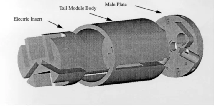
The tail section of the WASP vehicle, as seen in Figure 3.1, housed the tail servos, much of the electronic components of the vehicle (which were attached to the “male plate”), and was where the tail fins stowed. It had an outside diameter of 3.8” in order to give it clearance with the shell wall, which was 3.9” in diameter. The inner wall thickness varied throughout the section and was machined from a solid block of aluminum. There were two long slots cut out of the back of the section, each about ¼” wide and 2” long, which allowed the tail fins to deploy, as well as several bolt holes to connect this section to the wing module. The geometrical requirements for this section were to maximize the volume while not exceeding the maximum internal diameter of the shell, and to provide appropriate cutouts for the fins and bolts.
3.1.2 Loading
The loading of the tail section, as with the rest of the structure, was derived from the acceleration loads of the shell launch. The major design load was the set-back of 16,000 g’s pushing the entire mass of the vehicle against the tail section. This acceleration load was distributed evenly across the upper cross-sectional face of the tail section.
3.1.3 Boundary Conditions
The back of the tail section was bolted to the male plate, which housed the electronics. This boundary effectively clamped the back of the section. The other constraint on the tail section was the wall of the shell surrounding the flyer, which restricted the radial expansion of the section.
3.2 WASP I Design
The WASP I vehicle was designed to be fabricated mostly out of aluminum for ease of manufacturing and to save the time and expense of developing more complicated parts19. Consequently, the tail section of the vehicle weighed almost 4 lbs. The design was very conservative to ensure g-survivability without any yielding; however the excessive weight of the aft section proved to be a major factor in the uncontrolled crash of the subsequent test flyer.
3.3 Composite Trade Study
The first part to be re-designed for the WASP II flyer was the aft section with the objective of further reducing its weight while still retaining
g-several different possible configurations of the flyer. The first configuration was the baseline design in 7075 aluminum. The second was an optimized aluminum design, which accounted for the fact the loading was directly proportional to the weight of the section. Therefore, it was derived parametrically by varying both the load and cross-section as a function of thickness, producing the minimal weight section to meet the design stress of twice the yield stress, 70 Ksi. This optimization equality yielded a thickness of .48”, which therefore dictated the inertial load. The next two configurations modeled were both in graphite/epoxy composite. Both were quasi-isotropic AS4/3501-6 laminates; the first consisted of a constant section of 20 plies (02/+45/02/-45/02/90/0)s and the second consisted of 40 plies (02/+45/02 /-45/02/90/0)2s. Their weight was calculated based upon their volume and a density of .06 lbs/in3.
For the analysis, the aluminum parts were modeled in I-DEAS as solid elements and processed in I-DEAS as a linear model. The composite parts were also modeled in I-DEAS but as thin shell elements, and were processed in ABAQUS as a non-linear model since this FEA package is much more
accurate for advanced materials. All post-processing was performed in I-DEAS, a finite element analysis tool, which has a simple graphical interface.
The two areas of Von Mises stress chosen for comparison were the far-field stresses at the center of the cylinder between the slots, and the maximum stress concentration at the tip of the large slot. The stresses are tabulated in
Von Mises Stresses (ksi) Axial Strain (microstrain) Stress Strain
Material Comment Far Field Max Far Field Max MOS MOS
7075 AL Optimized 36 52 - - 1%
-AS4 Gr/Ep 20 Ply 70 84 2450 2770 0% 2%
AS4 Gr/Ep 40 Ply 36 42 1290 1400 49% 48%
Savings over Original AL Savings over Optimized AL
Material Comment Weight (g) Aft Overall Aft Overall
7075 AL Original 1860 - - n/a n/a
7075 AL Optimized 1138 39% 10% -
-AS4 Gr/Ep 20 Ply 143 92% 23% 87% 15%
AS4 Gr/Ep 40 Ply 277 85% 21% 76% 13%
Figure 3.2: Table of stresses found in tail section material trade-study
The stress margins of safety listed were calculated by taking the difference between twice the far field stress and the yield stress, and dividing it by the yield stress. The far field stress was used to tabulate these margins of safety along with an assumed stress concentration of two to be more conservative over the traditional use of the maximum stress in the model. A yield stress of 73 Ksi was used for the aluminum design; for the composite designs, a first ply failure was assumed to occur at a laminate stress of 140 Ksi, which was found using classical laminated plate theory (CLPT). For the composite sections, a strain margin of safety was also calculated using 5000 microstrain (.5%) as the strain limit.
These results show that a significant weight savings can be achieved over the original vehicle design by optimizing the aluminum configuration. As shown in Figure 3.3, a significant additional weight savi ngs can be achieved if composites are used as the primary material. Furthermore, an additional margin of safety can be achieved as a result. The first pair of percentages displayed compare the weight of the three new designs to the original design for both overall vehicles as well as just the weight of the aft section. The second set of percentages demonstrates the additional savings of a composite design over the optimized aluminum design, again comparing both the weight of the entire vehicle as well as the weight of just the aft section. In Chapter 4, an analytical procedure will be introduced to further investigate the advantages of composite material in the WASP design.
CHAPTER 4
ANALYTICAL PROCEDURES
The following chapter outlines the analytical procedures that were used to predict the response of composite tube sections with cutouts to high-g loading. This includes the use of Classical Laminated Plate Theory (CLPT), as well as the implementation of both static and dynamic structural finite element models.
4.1 Overview
The general procedure for analyzing the WASP composite sections can be followed in the flow chart in Figure 4.1. The analysis commenced with selecting a candidate laminate to be examined. A CLPT code (explained further in the following section) was written in Matlab, which would iterate the acceleration load until first ply failure as determined by the Tsai-Wu failure criterion20. This failure theory, which can be found in Figure 4.2, uses the anisotropic ultimate strength properties of the composite material to calculate
Figure 4.1: Analysis flow chart
ANALYSIS FLOW CHART
EQUATION SOLVER (Mathmatica)
Tsai-Wu failure theory constants tabulated Maximum stress for each direction entered
Failure load factor found
STRESS OUTPUT (ABAQUS-POST)
Stress solutions inported from ABAQUS Geometry and loads inspected Maximum stresses located and recorded
PROCESSOR (ABAQUS)
Material properties and laminate defined Load and boundary conditions defined Static model processed for nominal 1000 Lbs load
GEOMETRY (I-DEAS)
Model sketched in CAD environment Finite element model geometry defined Load and boundary condition groups selected
LAMINATE SELECTION (Matlab)
Composite laminate ply angles entered Graphite/epoxy material properties entered CLPT code using Tsai-Wu iterated to select laminate
failure constants, which are then equated with several combinations of the stress components. The next step was to use I-DEAS as a pre-processor and mesh generator.
There were two distinct configurations investigated; one with two long slots where the V-tail was stowed, and the other with two short slots where electronic inserts were placed. The geometry of the section to be studied was modeled and meshed, and then sets of boundary elements and nodes were grouped to be exported together into ABAQUS. Once in ABAQUS, material properties, boundary conditions and a nominal 1000 lbs axial compressive load were imposed via an input “script,” an outline of which can be seen in Figure
4.3. After being processed by ABAQUS, ABAQUS-Post was used to examine
the stress contours of the section for static models, and the message file was analyzed for the convergence of a buckling load factor (the load multiplier that causes the out-of-plane deformation to diverge) for dynamic models. Both a static and dynamic analysis was performed for each model.
For the static models, the three stress components—axial, circumferential and shear—were extracted from the elements with the highest stress state near the slot tip. These stresses along with the tabulated Tsai-Wu failure constants were then entered into Mathmatica. Since the laminate was assumed to behave linearly until first ply failure, the stresses in the cylinder would therefore scale linearly with the load applied to the model. Using this fact, the equation solver in Mathmatica was used to solve for the critical load
GEOMETRY Points Shells Groups DEFINITION Element Definitions Material Definitions Laminate Definitions CONSTRAINTS Boundary Conditions Loads OUTPUTS Results export Custom Routines
Figure 4.3: ABAQUS code outline
Figure 4.2: Tsai-Wu failure criterion and constants c t c t 12 2 66 c t 22 c t 2 c t 11 c t 1 2 1 12 3 66 2 2 22 2 1 11 2 2 1 1
Y
Y
X
X
5
.
0
F
S
1
F
Y
Y
1
F
Y
1
Y
1
F
X
X
1
F
X
1
X
1
F
1
F
2
F
F
F
F
F
−
=
=
−
=
+
=
−
=
+
=
=
σ
σ
+
σ
+
σ
+
σ
+
σ
+
σ
factor to be multiplied by the nominal load entered in ABAQUS, which would yield the first ply failure load as determined by the Tsai-Wu criterion.
4.2 Classical Laminated Plate Theory
CLPT was implemented by ABAQUS in this analysis to calculate the stresses in each ply layer. This theory assumes that all of the layers in a composite laminate are perfectly bonded together, and that each ply strains equally in the laminate coordinate system when subjected to a pure tensile or compressive load. A stress or strain is applied to the laminate, and using the above assumptions and a couple coordinate transformations, the stress in each ply can be calculated. Several books have been written explaining CLPT, including Mechanics of Composite Materials by Jones21. A Matlab code implementing this theory into a ply-by-ply failure analysis can be found in
Appendix A. Given cylinder dimensions and a laminate, this code would
continuously increase the acceleration load until first ply failure, using the Tsai-Wu theory as a failure criterion. Since this code could only analyze uniform cylindrical bodies without cut-outs and did not taking bending into account, it was only used as a preliminary laminate selection tool.
4.3 Static Model
This section describes how I-DEAS and ABAQUS were used to form a static finite element model. The generic geometry of the model was first created, and then supplemented with a loading scheme, boundary conditions and specific material properties in the ABAQUS input (.inp) file as described in the following sections. A sample of this file can be found in Appendix B. Once the edited file was run in ABAQUS, the restart (.res) file was viewed in ABAQUS-Post to observe the stress contours.
4.3.1 Geometry
Before the finite element analysis could be performed, it was necessary to model the shape of the section in I-DEAS. I-DEAS is a graphical program, which uses points, lines, curves and surfaces to define a model. The tail sections were drawn 3.5” in diameter and 5.5” in length. Next, depending on which of the two geometries was being worked on, a pair of ¼” rounded slots were cut from the geometry, either 2” or 5” in length. A semi-circle ¼” in diameter was also drawn at the top of the slot to accurately model the rounded edges of the WASP vehicle machined slots. These models’
Once the outline of the tube had been completed, the next step was to form surfaces from the boundaries. These surfaces were meshed with 8-noded S8R5 shell elements, whose properties were prescribed in a future step. A convergence study was performed to find the appropriate refinement for each curve, which in the end was limited by the scratch space available on the computer. The general rules followed were first to keep the scale in each direction constant so as to create square elements, and secondly to refine the mesh in the area around the slot tip to provide more accurate stress contours. For the same reason, 8-noded elements were selected since they quadratically interpolate displacement fields with the mid-side nodes as opposed to 4-noded quadrilateral elements that use linear interpolations.
Lastly, a surface mesh was formed on the top of the tube model, as seen in Figure 4.5. This was to provide a uniform pressure load on the structure, which will be described more in greater detail in the next section. The elements of this top plate were grouped as “force” to be exported in a special separated section, and the nodes around the bottom ring of the structure were exported in a group called “fixed.” The entire meshed model along with these specially selected sections were then exported into an ABAQUS format to be edited and processed.
3.5”
120
°
1 /8” short slot 1 /4” long slot fixed boundary2”
5.5”
5”
12 lbs @ 12,000 g’sSIDE VIEW
BOTTOM VIEW
Figure 4.4: Model geometry, applied load and boundary conditions
top- loading surface
4.3.2 Loading
The loading used in ABAQUS attempted to simulate the effect of the rest of the vehicle being accelerated into the tail section. To accomplish this, as described in the previous section, a top surface was meshed onto the finite element model. This surface was given a very stiff modulus so that it would not deform significantly under the load, and was meshed freely by I-DEAS. A uniform axial compression pressure load of 1000 psi was then applied in the ABAQUS input file to the “force” element set. Since the material properties entered (as described below) were linear, the stresses outputted by ABAQUS-Post could then be easily scaled by this magnitude of pressure.
4.3.3 Boundary Conditions
Using a similar method to how the load was applied, the boundary conditions were inserted into the ABAQUS input file. The boundary to be modeled was a clamp formed by the “male plate” which is attached to the bottom end of the tail section. To simulate this, in the input file the set of nodes referred to as “fixed” was restrained in all six degrees of freedom using the encastre command, thus modeling the plate as infinitely stiff. Some other boundary conditions were experimented with, such as restraining the hoop
Ply Property Value Units Ply Property Value Units
E11 142 GPa Xt 2356 GPa
E22 9.81 GPa Xc 1468 GPa
E33 9.81 GPa Yt 49.4 GPa
G12 6 GPa Yc 186 GPa G23 3.773 GPa S 105 GPa G13 6 GPa Thickness .134 mm V12 .3 Density 1580 Kg/m3 V23 .34 V13 .3
deformation at the top of the tube, although this had minimal effect on the model solutions.
4.3.4 Material Properties
The ABAQUS input files as exported by I-DEAS had only generic properties, which were then edited while in text format. The thin shell elements were given a laminate material card, which allows several layers of materials of different orientations to be attached together. Each of the ply layers were give n the material properties as given by Figure 4.6, which were supplied by the manufacturer Hexcel. There were 18 plies in the laminate, arranged [0/±45]3s. This ABAQUS material card used CLPT, and assumes that each ply layer is perfectly bonded to the next.
4.4 Dynamic model
Since there were relatively long slots in the length of the structure, it was uncertain whether the tubes would fail by fracture or buckling; therefore a dynamic model was also analyzed in ABAQUS. The dynamic model followed the same procedure as described above for the static model, using identical geometry, materials, loads and boundary conditions. The only difference occurred in the solution section of the input file, where linear buckling
(eigenvalue buckling) was specified instead of a static solution. A sample of this input file can also be found in Appendix B. The subspace iteration method was used to find the buckling load factor, and the number of vectors and iterations could also be specified in the input file. For the tail section, 3 vectors were chosen for quick convergence, and 30 iterations were chosen so the rate of convergence could be calculated. These solutions could be found in the message (.msg) file after the buckling problem had been processed in ABAQUS. Several different variations were experimented with in the buckling model, which will be further discussed in the results section. These variations included changing the elastic properties of the material, the tube’s length and diameter, and the layup. In the following chapter, the experimental techniques used to validate this analytical model will be discussed.
CHAPTER 5
EXPERIMENTAL PROCEDURES
The following chapter outlines the experimental procedures that were used to investigate the response of composite tube sections with cutouts to high-g loading. These sections are an idealization of the tail section of the WASP I vehicle, as described in Chapter 3. Both the manufacturing method implemented and a description of the two testing phases are included in this chapter.
5.1 Manufacturing Process
This section delineates the manufacturing process used to fabricate composite fuselage sections. This includes the material used, a detailed description of the processes implemented for curing, and subsequent machining. The procedure described produces three tubes each 14” long that are then machined into six 5½” long specimens.
5.1.1 Graphite/Epoxy Pre-Preg
All of the experiments were performed using AS4/3501-6 graphite epoxy pre-preg. This is TELAC’s standard composite material, so the procedures drawn up by the lab22 formed the basis for the manufacturing conducted here. First the roll of pre-preg, which is initially stored in a freezer, has to be thawed to room temperature before being removed from its plastic bag in order to prevent wrinkles due to moisture absorption. The roll is then placed on a wooden roller and unwound onto a cutting table, prior to being cut to the required lengths.
Since a 3.5” diameter mandrel has an 11” circumference, the standard TELAC templates could be used, yielding 12x14” sections of pre-preg. The 0° direction of fibers here is defined as axial, or in the 14” direction. The layup investigated was [0/±45]3s so for each tube manufactured six of each 0°, +45° and -45° plies had to be cut out. Since each layer increases the circumference of the layup around the mandrel, the outer-most uncured layer has a circumference of 12”, so a different procedure than the one described in this section would have to be used for any mandrel with diameter greater than 3.5”. The plies here were cut to identical lengths, and placed separated with backing paper in a vacuum bag in a freezer until they were used.
5.1.2 Cylindrical Mandrel
The hollow mandrel used for these cures was purchased from TW Metals23, and was custom machined in the student machine shop. It was 3.5” in diameter 2024 aluminum and 48” long. Aluminum was chosen because of its high thermal expansion, which would cause it to shrink more then the composite tube during cool down from the cure temperature, making it easier to remove the tube from the mandrel, which will be described later. Legs were constructed on the water-jet for the mandrel, which consisted of a square aluminum plate with 3.5” diameter hole cut out of the middle that was cut in half. A 1” diameter steel threaded rod was then passed through both plates to add rigidity, which was held in place by 2 steel bolts on either side of each plate. A vacuum port was then machined into the mandrel by drilling and tapping a hole 1” from the end of the tube. The threads were formed from the inside of the tube since the pipe fittings would be screwed in from that side. In order to attach the autoclave’s vacuum hose to the mandrel, a three part vacuum fitting assembly was threaded in the mandrel, sealed with Teflon
tape. It consisted of a short piece of pipe stock screwed into the hole, an elbow, and a long piece of pipe stock protruding from the tube and ending in a swage-lock fitting.
MATERIAL SIZE PIECES Guaranteed Non-Porous Teflon 11” x 15” 3
12” x 4” 4 14” x 5” 3
Porous Teflon 13” x 16” 3
Cork 11” 6
Bleeder paper 16” x width 3
4” x width 6
Glass bag 16” x width 3
Vacuum Bag 64” x width 1
Figure 5.1: Table of required cure bagging materials
Figure 5.2: Schematic of cure top-plate configuration
Mandrel with cylinder and bagging materials 0.008” Brass shim stock inner top plate 0.020” Aluminum shim
5.1.3 Pre-cure setup
Manufacturing closed cylindrical shapes with pre-preg composite introduced many complexities. This forced a deviation from the standard cure setup, which had been explored in the Draper “micro-satellite” project24 through trial and error of many cures. Figure 5.1 shows a checklist of materials that were needed to perform each cure of 6 specimens. Once these materials were cut out, the mandrel was scrubbed using methanol and scouring pads to give it a smooth surface. Masking tape was then wrapped around 2” at either end, and Mold Wiz was sprayed over the mandrel’s surface to protect it from epoxy. The tape was then removed and the area it was covering was cleaned with methanol. From this point on, handling of the mandrel was minimized. When it was necessary, latex gloves were worn.
Probably the most important part of the setup was the top plates. The top plates wrap around the pre-preg, and control the surface finish of the specimens. Often top plates are not used due to the additional complexity they add, and they can be replaced by using more bagging materials such as excessive bleeder paper. However, this approach can introduce surface wrinkles. Furthermore, having a metallic top plate present during the cure increases the consolidation of the epoxy compared to that achieved with more compliant bagging materials. Here, a two-part top plate system was used to minimize the effect on the gap where the two sides meet, as demonstrated in
three 10x14” pieces, and rolled into a curvature of 3.5” diameter. This would wrap snugly around the pre-preg leaving a 2” gap between its ends. This gap would then be filled by the second part, which consisted of 15 mil thick brass shim stock, cut to 4x14”. All of these pieces were sprayed with Freekote on all sides and allowed to dry before using them. Additionally, the aluminum pieces were coated with guaranteed non-porous teflon (GNPT) on the inside, which was attached using 3M Spray Adhesive.
The first cure performed only used a butt-joined piece of aluminum as the top plate, which created a large ridge in the cured specimens. This resulted in the selection of a two-part system. The various thicknesses and materials were chosen based on experiments performed trying to minimize the resulting ridges in the specimen. This final procedure still yielded some indented lines, however from inspection they were considered superficial.
5.1.4 Laying-up
The process for hand laying-up composite tubes is very time consuming. Originally it was thought that the pre-preg could be layed-up on a flat surface in a stair step fashion, however when implemented the variation in wrapping tension was too great and the radius was too small to correctly line up all of the ply layers. The alternative selected was to lay-up each ply layer individually on the mandrel. Since each of the 45° plies is cut into two
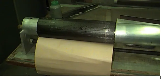
preserve the ply angles. This was done by removing one side of the backing from each piece of pre-preg, and pressing them together on a flat, hard surface. The prepared mandrel was placed without its legs on a clean glass table covered with GNPT. First three 0° plies were cut to 11” width, the backings were removed, and they were wrapped onto the mandrel separated by 1½” each to start each tube. Next a ±45° ply group was applied with the backing still attached in order to measure the length which needed to be trimmed. This ply group was then removed, and the three groups were trimmed to the proper length. After the backings had been removed, a 1” section of each ply group was pressed onto the underlying 0° ply, offset from the butt joint, and the rest of the ply group was left resting on the glass table. Pressure was then applied to the mandrel, and it was rolled across the table until the ply groups had been completely stuck to the previous layer. This process is then repeated for each ply until the final 0° ply, which does not need to be trimmed and the backing was not removed until the bagging materials were applied. A picture of the layed-up mandrel can be seen in Figure 5.3.
5.1.5 Cure Process
After the pre-preg was wrapped around the mandrel, the bagging materials that where cut out previously were placed on the mandrel as shown in the Figure 5.4. Again, many of these layers are non-standard, and were determined by an experimental process. The most important layers to the
Figure 5.3: Picture of layed-up mandrel
GNPT (w/adhesive) Composite laminate GNPT (w/adhesive) Duel layer top plate Porous Teflon Bleeder bag ( x 6) Fiberglass bag ( x 3) Vacuum bag Aluminum mandrel Cork 48” 14” 1.5” Composite cylinder Vacuum Port
survival of the cure were the layers of bleeder paper, which prevented the other layers from being epoxied to the mandrel. The vacuum bag was oversized so that wrinkles could be deliberately introduced instead of using a “doggy ear” method of bagging. Vacuum tape was placed on the mandrel at either end, and a short section was exposed to tack down the vacuum bag, which was then rolled onto the mandrel. A long piece of vacuum tape was then placed along the length of the mandrel on the vacuum bag where the seam was to be made. This length then extended down the circumference at either end where it overlapped the small section of tape that was already exposed. Finally all of the backing was removed, and the vacuum bag was tacked down at regular intervals in order to produce several small wrinkles, which could then be drawn to the side and pushed down.
The cure cycle used for these specimens is the standard TELAC cure cycle used for AS4/3501-6. The mandrel was placed in the TELAC autoclave, standing on the legs that were built for it. First a vacuum of as close to 30” Hg as possible was pulled on the specimens (no less then 25” Hg was tolerated), and then a pressure of 85 psig was applied. Once the correct pressure was attained, the temperature was ramped to 240°F and held for 1 hour to allow the epoxy to gel and remove the voids. Then another ramp to 350°F was imposed where the cure was held for two hours while the matrix cross-linked and the composite material is cured. Lastly a 5°F per minute cool down was used to cool the autoclave down to 180°F, at which point the
pressure was removed and the autoclave was turned off. The standard cure temperature, pressure and vacuum profiles and be seen in Figure 5.5.
5.1.6 Post-cure procedures
Once the mandrel was removed from the autoclave, all of the bagging materials were removed. This was done by making a lengthwise incision using a utility knife through the region of the bag that appears to have the least epoxy on the surface. If the incision was made deep enough, all of the layers of material were then peeled and unwrapped off the mandrel at once, and the specimens were still protected by the top plates. The top plates were then removed, which only left the composite tubes on the mandrel. The mandrel was then placed in a large freezer for approximately 15 minutes in order to shrink the aluminum tube even further, while the composite tubes would stay at relatively the same diameter.
The process for taking the tubes off the mandrel also took much trial and error. The final process, which worked the quickest and easiest, was to use the mandrel legs to pull off the composite tubes. First the bolts holding on the legs were all loosened and one of the legs was put flush against the near side of the tube furthest from the vacuum port. Next an aluminum block was placed on the end of the mandrel opposite the vacuum port, and the other leg was against this block. A furniture clamp was then mounted on each of the
Figure 5.5: Standard cure temperature, pressure and vacuum plots1 0 50 100 150 200 250 300 350 400 0 50 100 150 200 250 300 350 Temperature (F) Time (min) 0 20 40 60 80 100 0 50 100 150 200 250 300 350 Pressure (psi) Time (min) 0 5 10 15 20 25 30 0 50 100 150 200 250 300 350 Vacuum (in Hg) Time (min)
enough to overcome the static friction and charge holding the tubes on the mandrel, and they would slide right off. Sometimes however, the tubes had to be cranked all the way off the Guaranteed Non-Porous Teflon (GNPT) underneath them before they would slide off. Each tube was removed in this fashion one by one, each being moved away from the vacuum port side of the mandrel. Once removed, the 3 tubes were placed in the post-cure oven for 8 hours at 350°F.
5.1.7 Machining the specimens
After being post-cured, the samples were brought to the central machine shop where the initial machining took place. Two 5½” specimens were cut out of each composite tube using a continuous carbide grit band-saw blade. The edges were then smoothed using fine grit sandpaper to make the sides parallel to each other for testing purposes. Both of these tasks were contracted out to be performed by the machinists of that shop.
The six specimens were then taken to the student machine shop where the appropriate slot formations would be milled into them. Marks were placed on the tubes at locations where slots would be cut using a silver pen and a lathe tool head to measure the angles. The tubes were then clamped onto a milling machine, which was draped with bleeder paper to protect the machine. The tool used to cut the slots was a ¼” 2-flute carbide endmill
composite wall at the middle of the tube in order to prevent edge delaminations, and then moved towards the end of the slot. There the tool was lowered while out of the tube to the full thickness, and another pass of the tool was made from the outside to the inside to complete the slot. This two pass method alleviated much of the torque on the system, thus reducing the amount of delamination and displaced edge fibers. Lastly a file was used to round the edges of the slots and to remove any stray fibers. The specimens were then cleaned, labeled, and were ready for testing.
5.2 Test Fixtures
To simulate the appropriate boundary conditions during testing, two sets of test fixtures were manufactured. Both of these sets of parts were designed on AutoCad4, and were machine at Draper Laboratory.
5.2.1 Mass simulator
This part, as seen in Figure 5.6, was placed on the top surface of the specimens. It served the dual purpose of restraining the samples from compressing in the radial direction and to provide a uniform line load along the upper surface for both mechanical and air-gun testing. The dimensions of the cylindrical block were chosen to be 3” long by 3.8” diameter with a protruding ½” long cylinder of 3.5” diameter to fit inside the composite specimen with an
Figure 5.6: Aluminum mass simulator for tests
3.5” 3.7”
interference fit. The overall part weighed 4.0 lbs, was designed to obtain appropriate stress levels at feasible g-levels during air-gun testing. Two of these parts were machined to allow for replacement in the case of damage during air-gun testing.
5.2.2 Clamp simulator
This second part was also machined out of aluminum, although its dimensions were dictated to minimize its volume. As seen in Figure 5.7, each bottom fixture is ¾” x 3.8” diameter with a ½” deep and .15” groove turned into it to allow tubes to be seated in it. Six of these parts were machined to save time during testing. The samples were held into this fixture by a crystalline wax (CA #790) manufactured by Greater Southwest Chemicals, Inc. A small amount of wax was melted in a glass petrie dish on a hotplate at 150°F, and then poured to fill the bottom of each groove of the fixture. The fixtures were then placed on the hotplate at 250°F, and after allowing the wax to become clear, each specimen was inserted and then the system was cooled in a water bath. This wax could be continually reheated and cooled to place new specimens in the fixture, and the water-soluble wax was easily wiped cleaned.
5.3 Testing
This section describes the two series of tests that were performed. A total of 12 specimens were tested, half at MIT using a mechanical compression machine, and the rest at Picatinny Arsenal in a 155 mm air-gun.
5.3.1 Test Matrix
As described in previous chapters, two specimen configurations were investigated: long slotted and short slotted. From this we derive a fairly simple test matrix to validate the analytical codes, as seen in Figure 5.8. The details of each test will be described in the following sections, as well as why not all of these tests were successful.
5.3.2 Mechanical Compression tests
Six axial compression tests were performed in displacement control on the MTS testing machines in TELAC. These tests were carried out until failure, at a rate of .025” per minute. The load-displacement data was recorded using LabView5. Compression platens were placed on both heads of the MTS, and each specimen was loaded with mass and clamp fixtures in place, as