Design Method of a Modular Electronic Printed Circuit
Board Testing System
by
David McCalib, Jr.
B.Sc., Manufacturing Engineering Technology, and Mechanical Engineering
Oregon Institute of Technology, 2007, 2012
Submitted to the Department of Mechanical Engineering
in Partial Fulfillment of the Requirements for the Degree of
Master of Engineering in Manufacturing
at the
MASSACHUSETTS INSTITUTE OF TECHNOLGOY
September 2013
ARCHIN
E
MAASSACHUET IN 7EM~OF rE=CHNOLOGY
NOV
12
2013
LIBRARIES
0
David McCalib Jr, 2013, All rights reserved
The author hereby grants MIT permission to reproduce and distribute publicly paper and electronic copies
of this thesis document in whole or in part
Signature of Author
Department of Mechanical Engineering
August 9'4, 2013Certified by
Accepted by
Stanley B. Gershwin
Senior esearch Scientist Department of Mechanical Engineering
Thesis Supervisor
David E. Hardt
Ralph E. and Eloise F. Cross Professor of Mechanical Engineering
Chairman, Committee for Graduate Student
This page intentionally left blank
Design Method of a Modular Electronic Printed Circuit
Board Testing System
By
David McCalib, Jr.
Submitted to the Department of Mechanical Engineering on August
9th,2013 in
Partial Fulfillment of the Requirements for the Degree of
Master of Engineering in Manufacturing
Abstract
The failure rate of the printed circuit board electronic testing process is higher than acceptable
at a Lenze Americas factory. This thesis will understand the root causes of failure, and use
system engineering methods to decide what course of action should be taken. A Tradespace
analysis is used to help decompose some of the complexity into a visualization that simplifies
the decision process. The Tradespace analysis suggests that more utility can be achieved by
upgrading the design of existing test fixtures versus purchasing off of the shelf solutions.
The second phase will identify a design concept, offer specific design solutions, and finally a
fully designed system that is capable of improving the performance of the test fixtures in
electronic board test area by 50%. The system is then upgradable with in-line conveyors to run
autonomously decoupling the operator from the process.
Thesis Supervisor: Stanley B. Gershwin
Title: Senior Research Scientist Department of Mechanical Engineering
Acknowledgements
"Only those who attempt the absurd can achieve the impossible." MC Escher
On this journey at MIT, I have will never forget the time spent with Vrushank, and Joseph, as well as all of the MEngM cohort. This was a great experience, one that I never forget. The teachers that really made a difference for me; Professors David Hardt, Alex Slocum, Martin Culpepper, and Charles Fine. Their instruction in and around class was extremely valuable. Professors Matt Kressy, Warren Seering, and Steve Eppinger really expanded my MIT experience with the Product Design and Development class.
I would especially like to acknowledge Professor Daniel Whitney, who taught a special session over IAP
to educate us on all on what goes into understanding mechanical assemblies, and its role in product development. To my adviser Stanley B. Gershwin, who is a living testament to what a consistent, enthusiastic, mentor can really be. His guidance will echo in my life for years to come. Jonathan B. Hopkins led me to understand his work on FACT, and changed the way I look at the design of compliant mechanical systems -He has been a great resource, and a wealth of information.
I would like to thank my family, helping me understand the importance of hard work, and striving for the
best education in and outside of the classroom. Debora thank you for your support, and enthusiasm, you are a light in my life that I am truly blessed to receive.
"Don't worry. As long as you hit that wire with the connecting hook at precisely 88 miles per hour, the instant the lightning strikes the tower... everything will be fine." Dr. Emmett Brown
Table of Contents
ABSTRACT ... 3
ACKNOW LEDGEM ENTS ... 4
TABLE OF CONTENTS ... 5
LIST OF FIGURES ... 7
1. INTRODUCTION ... 9
1.1. COM PANY BACKGROUND AND M ANUFACTURING ... 9
1.2. CONTROL BOARDS ... 10
1.3. POW ER BOARDS...10
1.4. ELECTRONIC BOARD TEST AREA ... 11
2. PROBLEM STATEM ENT ... 11
2.1. REPAIR ISSUES AT ELECTRONIC BOARD TEST ... 12
2.2. PCB STRAIN DURING THE TEST...12
2.3. BACKGROUND LITERATURE REVIEW ... 13
3. CLASSIFICATION OF DIFFERENT ATE M ETHODS ... 14
3.1. IN-CIRCU IT TEST (ICT) ... 14
3.2. FUNCTIONAL TEST (FT)...14
3.3. TEST SYSTEM S ARCHITECTURE ... 15
3.4. COM PLIANT SPRING POGO ... 15
3.5. BED OF NAILS...16
3.6. VACUUM ASSISTED TESTING ... 17
3.7. IN-LINE AUTOM ATED TTEST ... 17
3.8. FUTURE M ANUFACTURING FACILITY LAYOUT... 18
3.9. PROJECT DESIGN GOALS...19
4. M ETHODOLOGY...20
4.1. NEED IDENTIFICATION...20
4.2. THE DESIGN OF FACTORY PRODUCTION TEST EQUIPM ENT... 21
4.3. THE M AKE VS. BUY DECISION ... 22
4.4. ATTRIBUTE DEFINITION ... 22
4.5. DESIGN VARIABLE/VECTOR: ... 22
4.6. TRADE SPACE DECISION M AKING PROCESS ... 23
5. DESIGN CONCEPT ... 26
6. FUNCTIONAL REQUIREM ENTS AND SYSTEM DESIGN... 26
6.1. EXACT CONSTRAINT OF THE UUT: ... 28
6.2. CANTILEVERED GUIDE M ECHANISM ... 30
6.3. ASSEM BLY DESIGN OVERVIEW ... 31
7. KEY CHARACTERISTICS DEFINITION ... 33
7.1. VARIATION ANALYSIS...35
7.2. Z ACTUATION FORCE PROFILE ... 37
7.3. KINEM ATIC COUPLING ... 38
7.4. TEST FIXTURE STAND-OFF PLATE ... 39
8. M ATERIALS AN D COST ... 40
9. SUM M ARY AND CONCLUSIONS ... 42
10. AREAS FOR FUTURE INVESTIGATION...43
11. APPENDIX...43
11.1. DIFFERENCE BETW EEN M ATES AND CONNECTIONS...43
11.2. FEATURE M ODEL OF ASSEM BLIES...43
11.3. CANTILEVER CALCULATIONS ... 47
11.4. LEAD SCREW AND SERVO SIZING...47
11.5. KINEM ATIC COUPLING M ATERIAL SELECTION...so REFERENCES ... 52
List of Figures
FIGURE 1: THESIS STRUCTURE ... 9
FIGURE 2: A LENZE PCB CONTROL BOARD ... 10
FIGURE 3: A LENZE POW ER BOARD PCB W ITH CAPACITOR PLATE ... 11
FIGURE 4: REPRESENTATIVE M ECHANICAL FIXTURE...12
FIGURE 5: FEA STRESS PLOT [3]...13
FIGURE 6: ADAPTED FROM VAN LOAN ET A L [8] ... 14
FIGURE 7: SYSTEM ARCHITECTURE E [9] ... 15
FIGURE 8: PICTURE OF A COMMERCIALLY AVAILABLE SPRING POGO. [10] ... 16
FIGURE 9: AN EXAMPLE OF A BED OF NAILS PLATFORM [11]...16
FIGURE 10: VACUUM ASSISTED FIXTURE [12] . ... 17
FIGURE 11 -AGILENT 11000 ATE [13]...18
FIGURE 12 - INLINE TESTING AGILENT 11000 [13] ... 18
FIGURE 13: DEPICTION OF PROPOSED FUTURE STATE PCB MANUFACTURING LINE [16] ... 19
FIGURE 14: DATA COLLECTED BY LENZE ELECTRONIC BOARD TEST REPAIR DEPARTMENT ... 21
FIGURE 15 -TRADESPACE EXAMPLE [19]... 23
FIGURE 16 - VALUE DEPICTION SEARI [21]...23
FIGURE 17: FOCUS OF RESEARCH EFFORTS...24
FIGURE 18: PURCHASED VS. DESIGN TRADESPACE W ITH PARETO FRONTIER. ... 25
FIGURE 19: TRADESPACE ATTRIBUTE COMPARISON HISTOGRAM. ... 25
FIGURE 20: DIAGRAM SHOW ING THE CONSTRAINING POSITIONS OF THE FIXTURE PINS... 29
FIGURE 21: COMMERCIALLY AVAILABLE CIRCUIT BOARD GUIDE PINS [26]... 29
FIGURE 22: SIDE VIEW OF PCB W ITH EXACT CONSTRAINT ... 30
FIGURE 23: ANGLED FRONT VIEW OF PROTOTYPE W ITH MISUMI GUIDE PINS ... 30
FIGURE 24: FRONT AND ISO VIEW OF BASE PLATE ASSEMBLY... 31
FIGURE 25: TEST FIXTURE ASSEMBLY...31
FIGURE 26: ISO OF BASE PLATE AND TEST FIXTURE ASSEMBLED ... 32
FIGURE 27: FRONT VIEW OF THE VERTICAL SLIDER ASSEMBLY ... 32
FIGURE 28: ISO OF BASE PLATE, TEST FIXTURE, AND VERTICAL SLIDER ASSEMBLIES... 33
FIGURE 29: DIAGRAM OF ASSEMBLY DESIGN PROCESS [27]...34
FIGURE 30: CHAINS OF DELIVERY FOR KCS IN SYSTEM ... ... ... 34
FIGURE 31 - SIDE VIEW OF AUTOMATIC TESTING FIXTURE DESIGN OVERLAID WITH DFC IN THE FULLY OPEN POSITION ... 35
FIGURE 32: PICTURE OF MONTE CARLO POSITIONAL ERROR OF PUSHER PIN ... 36
FIGURE 33: ERROR BUDGET W ORKSHEET EXCEL ... 37
FIGURE 34: M INITAB CAPABILITY OF ASSEM BLY ... 37
FIGURE 35: LOADING DIAGRAM FROM PIN FORCE...38
FIGURE 36: PICTURE DEMONSTRATING THE Z OFFSET FROM POGO'S ... 38
FIGURE 37: 300MM SILICON WAFER FOU P WITH KCPL ON BOTTOM ... 39
FIGURE 38: SIDE VIEW OF TEST FIXTURE ASSEMBLY WITH SPRING PLATE AND UUT ... 40
FIGURE 39: TOP VIEW OF SPRING PLATE AND UUT ... .... 40
FIGURE 40: A 3 REPORT PAGE 1 ... 41
FIGURE 41: A 3 REPORT PAGE 2 ... 42
FIGURE 42 -SIDE VIEW OF AUTOMATIC TESTING FIXTURE DESIGN OVERLAID WITH DFC IN THE FULLY OPEN POSITION ... 46
FIGURE 43: PARTS JOINED BY A CHAIN OF FRAMES TO DELIVER A KC [27]...46
FIGURE 44: COOPERHILL SERVOSIZER DATA INPUT PAGE FOR LEAD SCREW ... 48
FIGURE 45: M OTOR DATA INPUT PAGE...48
FIGURE 46: LENZE MCS06141 TORQUE CURVE [33] ... ... 49
FIGURE 47: VELOCITY AND TORQUE GRAPHS AS A FUNCTION OF TIME ... 49
FIGURE 48: PICTURE VIEW OF FRETTING OF SHAFT [34] ... 50
FIGURE 49: PSZ WEAR AFTER 100-HOUR FRETTING TEST VERSUS D2 STEEL (50-MM AMPLITUDE, 10 LBF) [34]...51
FIGURE 50: FRETTING WEAR VOLUMES FOR VARIOUS COUPLES (10 LB., 1.7Hz, 100 HR., 50 MM) [34] ... 51
1.
Introduction
The purpose of this thesis is to guide the reader on the methods used to deliver a solution to a process bottleneck at Lenze America manufacturing plant. A team of MIT Master of Engineering in
Manufacturing (MEngM) students researched this bottleneck and other areas for improvement identified
by the executive management. An upgrade to the existing electronic board test (EBT) strategy was
proposed, evaluated, designed, and presented to Lenze. The thesis is split into two stages. The first stage was identifying the problems at the electronic board test area that caused multiple failures of test fixtures, along with conducting a make vs. buy decision using a Trade Space analysis. The second stage is the design of a systematic upgrade strategy to improve the reliability of the existing testing fixtures as shown in Figure 1.
Par1Part 2
L---Figure 1: Thesis Structure
Other projects conducted by other MIT-MEngM students focused on plant layout optimization for current production and discrete event simulation for future products. The research was carried out at the
Uxbridge, MA facility, which primarily manufactures electronic circuit boards, assemblies, motor inverter drives, and servo motor drives.
1.1. Company Background and Manufacturing
Lenze America used to be formally known as AC-Tech before the acquisition by Lenze, a German company. The portfolio includes frequency inverter drives, servo drives, and motors. At Lenze America (Uxbridge), the main focus is the manufacture of printed circuit boards (PCB) and subsequent assembly into electronic drives.
These are manufactured using commercially available surface mount technology (SMT) to make the different PCB required for each product. The manufacturing of the PCB is done from vendor supplied laminates.
"Surface Mounting has become a mature process, and is implemented on a global basis. What started out as a new name for "planar mounting" has become the industry normfor electronic assemblies. The most obvious benefits of Surface Mount Technology (SMT) compared to older through-hole (TH) technology is increased circuit density and improved electrical performance. Less obvious benefits include reduced process costs, higher product quality, reduced handling costs, and higher reliability. Most of the SMT package types also ease assembly automation, rework and repair. Because of the complexity and density of some assemblies (e.g. intermixed components on both sides of a printed board), proper design and process control are essential if the reduction of processing costs, rework and repair are to be achieved". [1]
Lenze aggregates different board family types into the same layout and upgrades the components to higher power levels, when required. It has been Lenze's operational strategy to provide the quantity the customer wants, regardless of the quantity of the order. There are a lot of instances where small orders are run through the factory, creating additional requirements for reliability and change overs that are fast and efficient, in EBT.
1.2. Control Boards
A control board is typically a low power board (24 Volts or less) using the same SMT process and is
assembled with the power board at drive assembly. This is considered the brains of the drive since it takes input signals and voltages and then controls the power MOSFET [2]. The power board delivers the appropriate power to the motor. Control boards are separated from the power boards in the drive
assembly. As a requirement for motor horsepower (HP) goes up, the same control board can be used and the corresponding power board can be assembled to meet the requirements. These boards go through in-circuit testing at the EBT area. Figure 2 shows a top view of a control board representation.
Figure 2: A Lenze PCB Control Board
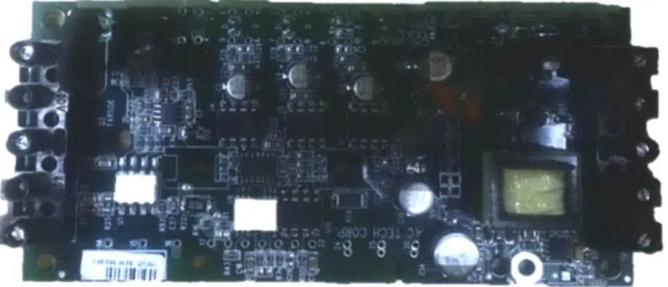
1.3. Power Boards
One laminate layout board can service multiple different power boards. Different components are added to handle the increased horsepower of the drive. Power boards and control boards are assembled into the drive enclosure.
These power boards or unit under test as they are called in industry (UUT) go through functional testing in the electronic board test (EBT) area.
The test fixtures require higher power POGO contact with the UUT. Voltage levels as high as 460V (3-phase AC) pass through the UUT as if they were under actual loaded conditions turning an electric motor. After the UUT pass the inspection and functional testing they are ready to be assembled into the drive assembly. After the assembly is complete the drive is tested again under functional loaded conditions, and a more severe load is applied. The goal is to ensure 100% product conformance within specifications, so that the customer is given a product that will work every time. Figure 3 shows a representative top view of a power board with capacitor plate, where capacitors are mounted. The contact points for the electrical test are on the bottom of the UUT.
Figure 3: A Lenze Power Board PCB with Capacitor Plate
1.4. Electronic Board Test Area
The electronic board test area is where all of the board level testing occurs. It is supported by an engineering group that designs test fixtures, electronic circuitry, and automated test programs that are used by the technicians to conduct in-circuit and functional tests. AC-tech the original company used very rudimentary test fixtures to test the original product. The original design circuit density was lower than the newer Lenze product offering. These older AC-tech drives were scheduled to be made obsolete, but given the popularity in the market place the decision to migrate customers to newer products has been slow. This means that some of the original test fixtures still remain in use today. This complicates improvements efforts since there are different designs. In 2005, the company started to standardize on using a PCB to hold POGO pin test points. The majorities of the fixtures are setup in this manner. These are the fixtures that received the most attention, since they make up the majority on the floor. Since Lenze used a PCB manufacturing process similar to the process used for the product, engineering data was more available to be used in designing upgrades. The engineering data did not exist in great detail for the older fixtures. One of the challenges presented to the company was what direction makes the most sense for Lenze, given that additional products are manufactured in the German location. The German site has been using more automated methods, and reporting better Mean-Time-to-Failure with German test fixtures, than Lenze America.
2. Problem Statement
At the beginning of the MIT research internship, manufacturing engineering resources had been setup for two years. Large improvements had been made to lead time and inventory in the PCB line up to EBT. However, bottlenecks still remained in the EBT process, due in large part to mechanical failures and repairs of test fixtures. These occurrences were well documented within the organization. The disruption to the process "turns" was widely felt as variation in process velocity was attributed to this process. The EBT is a critical quality process that ensures that the printed circuit boards (PCB) are manufactured correctly before being assembled into drives and cannot be skipped. Lenze needed to improve the mechanical performance of the electronic test fixture. A staff of 4-5 technicians worked to keep the over 200 fixtures up to production, and on preventative maintenance schedules. The EBT process had an
unacceptably high number of repairs that required extra resources to try and keep the equipment up.
2.1. Repair Issues at Electronic Board Test
The author investigated the root cause of the faults and current EBT design methodology, from concept in Cad to production on the floor. The electronic test engineering group had experimented with two different clamping design concepts previously, but both had never made it to production. One had been prototyped in the lab, and the other concept was designed in CAD to demonstrate the idea. They were both done in isolation and not in a systematic manner incorporating all of the ultimate stakeholders. Historically once a test fixture had been qualified at the first article acceptance of a product through the process the fixture was never upgraded to a robust design allowing 1000's of boards to run on them. In essence Lenze was going to production with test fixtures that had been only brought up to a level of prototype. Once production demands were placed on the fixtures, there was never a chance to go back and update the design for more robust reliability. Even though capable of determining if a PCB was not in the specified voltage tolerance, the reliability was not to the level that allowed for consistent throughput of WIP.
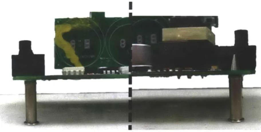
2.2. PCB Strain during the Test
The method to conduct a test is to first place the PCB on 4 guide pins, allowing it to rest on the POGO test points. A mechanical clamp is then brought into position over the PCB, and then engaged or latched. This resulting motion forces the PCB down into contact with the POGO's. When the clamping
mechanism is actuated during the test, mechanical strains are placed on the board. Solder bonded components can become damaged if the PCB is subjected to loads outside the accepted range. Figure 4 shows a fixture that is used for testing. The black and white connectors at the back are used to connect the circuits from the receiver to the fixture.
T Spacer
Mechanical Clamp
GuTidePi n
TF-254----Figure 4: Representative Mechanical Fixture
There is a considerable amount of research that has been done to measure strains placed on the board
during testing [3]. FEA simulation of test point and fixturing points give a method to reduce the deflections during testing.
The Global Trade Organization - IPC (IPC/JEDEC-9704A) has outlined methods for testing the amount
of stress that is placed on the boards using strain gages to experimentally verify with simulation methods. With the current method of mechanical fixture, it becomes difficult to setup correctly to reduce these strains. At Lenze there are fixtures that strain the PCB close to the allowable amount. It is desired to reduce this effect in this process.
Figure 5: FEA Stress Plot 131
Currently with the existing mechanical fixturing systems it is difficult to setup the clamps correctly to reduce the mechanical strain on the boards. Figure 5 shows FEA similar to PCB being tested at Lenze, demonstrating the extent that some companies go to reduce the stress on PCB.
2.3. Background Literature Review
The Automated Test Equipment (ATE) industry originated from companies like Teradyne and Genrad, filling a need to test ever greater circuit densities.
Over the last 30 years, there has been consolidation in the industry and movement of a lot of PCB
manufacturing to China [4] and other countries. A review of the history of the ATE industry can be found in Chiu [5]. There are multiple different vendors of fixtures, testing methods, and automated test
equipment in existence, as found in the industry guide of ATE World [6]. In this industry guide, more than 138 different suppliers were listed for various different ATE solutions. The author went through the guide and exhaustively searched the vendor list, identifying information used later in the Tradespace decision method. Phone conversations, request for quotes, and estimates were used to try and understand what is available on the marketplace for solutions.
Peet [7] describes the difficulties migrating from existing ATE to newer improved systems. He says
"Fixtures, as well as A TE, age and should be better rebuilt when possible and convenient. In many cases unfortunately this might prove not economically viable. Particularly when fixtures include active electronic, a large part of them is part of the project or simply the bill is too high. In such cases
building a fixture adapter between the new ATE receiver and the old fixtures is the preferred solution. Once again, the flexibility of the new A TE to provide adequate number of non-multiplexed
independently programmable analog/digital resources on every pin would greatly simplify and reduce the cost of thefixture adapter." This was part of the difficulty early on in the research. Trying to
understand what option made the most sense to pursue given the hundreds of test fixtures that were present, and hundreds of potential vendors. This information reinforced the difficulty given existing test assets versus a direction to invest money in newer technology.
A comprehensive literature review was conducted to understand what technology was listed in the
protected space of the Unites States Patent and Trademark Office (USPTO). In Van Loan et al. [8], a system is designed that is similar to the method that Lenze employs with regards the complaint POGO test pin. Lenze does not utilize their fixtures with a wireless configuration, as described in the patent. Each POGO is soldered in place to a test measurement PCB, and then a connecter is present on the PCB board. Figure 6 shows art from a patent demonstrating Spring POGO making contact to the UUT. In this case double acting POGO are installed.
PCB Unit Under Test
10 14 30 28 20 30 18 16 2 6 38 22 4 24 40 2 341 436 3422Spring POGO
Figure 6: Adapted from Van Loan et al [8]
3.
Classification of Different ATE Methods
Early on in the research at Lenze, the author needed better understanding of what electronic test meant at Lenze and in industry with respect to the different systems available and testing techniques. After the comprehensive literature review and discussions with vendors from the ATE industry, the following classifications of testing techniques and devices can be established. Different test methods exist at Lenze, and for different reasons outlined below.
3.1. In-circuit Test (ICT)
ICT is a low power test that checks the PCB for opens, shorts, deviations from expected resistance,
voltage, and other quantities. It does not simulate loads on the board and is typically done for control boards. Test probes make contact with the PCB under test. Most of the purchased testing solutions are for
ICT. Low cost ICT systems cost $10,000 - $30,000; with fully automatic systems costing over $100,000.
3.2. Functional Test (FT)
A low and high power FT is conducted to simulate loads on power boards, similar to what they would see
in the working environment. It consists of two steps:
1.
First is to apply low power to check for non-conformance similar to an ICT.2. Once this has passed, the power levels are increased and simulated motor loads are placed on the board.
The requirements are strongly related to the type of product being functionally tested. There are large variations in voltages, logic, signals, and power requirements. The majority of functional testers are built very specifically for the product being tested.
The possibility of eliminating ICT and FT from the process flow was investigated; but ultimately is not achievable. There are certain tests that are not conducted at drive test that must be done at functional test. The rework probabilities for a failed test require FT before assembly.
An assembled drive failure can mean that the unit is destroyed and not capable of being reworked. The preferred method is to understand the quality failure early on in the process and fix problems before they migrate down the line. This is an inherent cost of quality that the company incurs to ensure that the product is conforming. There is a lot of focus of reducing the cycle time at this operation.
3.3. Test Systems Architecture
Test systems are comprised of different elements that make the entire architecture. At Lenze the analog and digital instrumentation is housed in a separate enclosure from the receiver and fixture. The UUT mates with the fixture using the spring POGO connections. Figure 8 shows a functional block diagram outlining how the different components of the architecture are related.
Chanroe HVI
IL
Figure 7: System Architecture [9]
3.4. Compliant Spring POGO
POGO test points are designed to be compliant and maintain electrical connectivity during displacement
that occurs during the test. The spring force is required to break through any flux residue or oxide that forms due to standard processing from the SMT solder reflow and wave solder operations. Different tip geometries and diameters can be selected based upon which test point is required. The POGO's are engineered and certified to maintain a constant electrical resistance during the entire stroke of the POGO. This is important as different POGO's are displaced differently. This is because the topography of the
UUT varies with through-hole component leads and solder pads that have natural variation. If the
resistance changed as a function of height, then test results would be affected by the natural variation from the topography changes. Figure 8 shows one style of tip geometry of a spring POGO. Multiple different styles are available depending on requirements of the UUT.
D7 -. I
? UNIT:mm
~1
Figure 8: Picture of a commercially available spring POGO. [10]
3.5.
Bed of Nails
This is a traditional test method where a matrix of corresponding spring compliant test probe pins are aligned with the test points on the PCB. The PCB is placed on the bed and then brought to make contact with the spring pins. Care must be taken to ensure that the board is flat and that enough force is delivered to make sure the POGO tips have broken through the oxide layer. The arrangement of the POGOs can be done with an Epoxy Phenolic glass cloth laminate sheet or in a PCB as in the case of Lenze. When the
UUT is placed on top of the bed of nails and pressed down, the connection is made through the test points
and UUT. The POGO's are either soldered in place or wired back to the testing circuitry, enabling the test. Figure 9 is an illustration of a guided top mounted pusher plate used to bring the UUT in contact with the spring POGO's.
Gu[DE P NS
A
TOOLING PINS TEST PINS AII
AL A~ 11 I I II1-
-PRESS PLATE MID PLATE -RON PLA TE -GUIDE PLiTESHEET METAL S[DE BRACKET
Figure 9: An example of a Bed of Nails Platform [11]
3.6. Vacuum Assisted Testing
In the vacuum assisted testing method, the PCB-UUT is placed on a plate. A vacuum is applied to draw the board down to make contact with the spring pins on the bottom. The UUT is placed on the top and vacuum is applied. These test fixtures are typically manufactured by Teradyne or Agilent. Figure 10 demonstrates a vacuum fixture found in practice. Notice lack of a top mounted clamp plate. Vacuum assisted testing is actuated from the bottom sides of the fixture.
477
Figure 10: Vacuum Assisted Fixture [12].
3.7. In-line Automated Test
In line automated test methods are used to automatically place the PCB into the testing fixture with the use of conveyors. While fast and capable of removing the operator from the testing environment, these systems are expensive. The base testing station is required along with an additional in-line conveyor. The PCB is transferred along the in-line conveyor and then placed correct position with a board stopper. Then the inline conveyor lowers the board into the fixture. Since there are high voltages and a motivation to remove operator variability, these automated systems offer a solution. A truly operator decoupled setup requires a manufacturing execution system to glue together the different process modules into one system. For example, a PCB might come out of the wave solder process and need to move on a conveyor to a through-hole process and then to test. A system must be in charge of the material handling of the boards from station to station.
Figure II and Figure 12 are examples of an Agilent ilOOO ATE [13] and an inline conveyor system. Utilizing this setup, a manufacture can start to have full automation strategies removing the operator from the testing process. The i 1000 uses 3 vertical guides to ensure the vertical, planar guided action of the
PCB into the test points.
Figure 11 - Agilent ilOOO ATE [13]
Figure 12
-
Inline Testing Agilent ilOOO [13]
3.8. Future Manufacturing Facility Layout
In discussions with the Lenze engineering team, the following high level considerations were made in regards to a future state of continuous flow instead of the batch manufacturing system that they currently employ. The work by Falvella [14] and Phadnis [15] outline the direction that Lenze desires to take over the next few years. Falvella shows how to implement the migration while still keeping production going in the factory. Phadnis works on simulation methods to understand capacities and resource utilization. The EBT test engineering group made a decision to start using the systems that the German site uses for test equipment for all new products. This limited the author's scope of research to methods to improve the reliability for the existing test fixtures.
These existing fixtures are scheduled to be in production for the next 5-10 years, and will remain a process bottle neck if just left alone to be obsoleted. Along with the fact that market demands seem to extend the life based upon popularity with sales.
The Lenze teams consisted of Manufacturing Engineering, Electronic Test Engineering, and the Test Operation leads members that were included in early reviews. Information from the group was taken into consideration when figuring out the make versus buy decisions given the location, resources, capability, and manufacturing processes available to Lenze for the existing test equipment.
3.9. Project Design Goals
Improve the mechanical coupling of the UUT to the fixture, with a reduction of repairs in the system by
50%. Achieve: *0 * *0 e0 *0
Reliability
Safety RepeatabilityCost Appropriate Solution Standardization
Automatic Operation
The German plant has designed for full automation in some instances of their electronic test. Figure 13 is representative of a continuous flowing line serving as the inspiration for Lenze's future state. While Germany had a few automated lines, there was substantial product that remained that would be phased out in the next 5-10 years. In these cases it didn't make sense to invest the capital to re do the testing strategy on the previous boards. A system that could be purchased or designed that would allow for expansion into automatic flow would be an ideal solution. Figure 13 was shown to Lenze and became a representation of the direction that they had been working towards.
Fal
Sokier Bum-oi
printing placement 12 l defed deeotion
andl Manual
VIU00I inspection
Figure 13: Depiction of proposed future state PCB manufacturing line [16]
4.
Methodology
4.1. Need Identification
The purpose of this chapter is to identify needs within Lenze to improve the test fixtures. Research uncovers previous design guidelines from Nick De Wolf. Using these along with attributes selected by Lenze a Tradespace analysis is conducted. Interviews with engineers, repair technicians, repair
department managers, and test technicians occurred over a two month period. In one instance time was spent with test technicians going over the procedures line by line, so the intent of the specific test could be identified. Efforts were placed into creating new procedures from scratch, including pictures of each step
in the process to identify the actual test requirements. After the initial research into the process, a formal design requirements meeting was held with members of engineering, manufacturing, electronic board test engineering in an effort to try and identify needs of the existing testing methods. One need that was
identified was in the process documentation. A separate team was created to investigate if the
documentation could be improved with the integration of outside technical writing resources. Ultimately after interviewing many different technical writing companies, it was decided to keep the documentation control in-house.
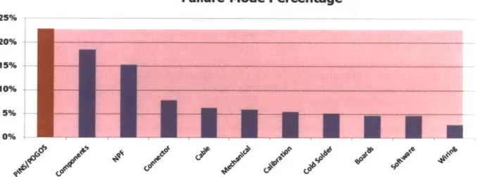
Observations and categorization of repair and failure modes were identified using data stored by the repair department. Mechanical Pin and POGO failures account for the majority of percentage repairs at
23% (3 month average time interval). This became the immediate research focus for mechanical
upgrades. If the improvements could include the pins, POGO's, connector and cable, then approximately
50% of failures could be eliminated.
Failure Mode Percentage
25% 20% 15% 10% 0p 6/ ~
/
20 1P a g eFigure 14: Data collected by Lenze Electronic Board Test Repair department
Failure Mode Percentage
25% 20%7 15% '10% 5% 0%
Figure 14Figure 14: Shows the histogram of failure modes. The needs identification found that
mechanical coupling and pins and POGO's were the highest failure mode that caused repair orders. This was from data that is recorded every time a fixture went down for repair, and was supplied by the repair department. It is stored on an Access database that correlates the incoming reason with the root cause that was assigned.
A "NPF" code means that a repair order was issued, but when the repair technician tried to reproduce the
fault, they were not able to identify a cause. This accounted for 15% of repair codes.
A recommendation was made to have the technician respond immediately to the repair order, and try to
observe without removing the fixture from the station.
The constraints in this systematic change are the manpower resources. If the technicians are on other calls they might not be available. The recommendation was to let the test station sit until they could get to it, so that a true root cause could be identified.
4.2. The Design of Factory Production Test Equipment
During the prior art search materials regarding the design of production test equipment had previously been dictated by the inventor and founder of Terradyne; Nick De Wolf [17].
1. It must be reliable.
2. It must be safe to use, and almost impossible to cause injury.
3. It must use good components and circuits.
4. It should be simple, to ease maintenance.
5. It must be easily calibrated with simple gear.
6. It must operate in a wide range of supply voltages. 7. It must operate in a wide range of temperatures.
8. It must be reproducible. If several sets are built, they must read the same thing, even if that
involves a loss in overall absolute accuracy.
9. It must be simple to maintain and accessible.
10. The operating portion of the gear at the operator's station must be small to prevent overcrowding. 11. It must test only the desired characteristics and not be responsive to other parameters, or varying
quality may result as product changes are made. 12. It must be accurate.
13. It must be stable.
14. It must be capable of a complete test in a short period of time, or testing expense will increase.
15. It must require a minimum of thought on the part of the operator. 16. It must not fatigue the operator, or mistakes will occur.
17. It should be reasonably neat in appearance. This creates confidence in the equipment. 18. It should be flexible enough to allow for specification changes that inevitably occur.
19. It must favor the rejection of bad units over their acceptance, in respect to predictable drifts and
failure. This applies particularly to automatic test equipment fail safe! 20. It should be reasonable quiet and cool and not damage tested units.
Remember the operator, who is 2/3 of the equipment. 21. It must give repeatable results.
This list is a great reference for identifying design parameters and attributes that will deliver a robust solution. These items will be referenced in general when making design decisions, and creating the specific functional requirements.
4.3. The Make vs. Buy decision
It was necessary to decide whether to purchase off of the shelf solutions or look for a design improvement method. There are a host of decision making methods. The use of a trade space exploration method was pursued, to find a visual representation of the solutions that could work for the requirements of Lenze. Tradespace is defined as a multivariate representation of interactions between attributes and design vectors. The ultimate goal of Tradespace exploration is to understand where tradeoffs give rise, and the identification of the Pareto frontier in selecting between multiple different candidate options.
4.4. Attribute Definition
An attribute is defined as a decision perceived metric that reflects how well a decision maker-defines objective is met. For example an attribute could be repeatability, or cycle time. These are used to vet different design variables when trying to make a decision. An attribute list was created that included different categories of performance that was desired by Lenze.
* Estimated Reliability (A function of the complexity and number of power sources) * Safety (A function of the power sources, and exposed paths for shock, pinching, or injury) * Repeatability (The estimated repeatability of the process given the design)
* Cycle Time (Estimated based on the work envelop and number of steps to actuate)
* Ergonomic Impact (A function of mechanical force required for the operator to initiate the test) 9 Automation Upgradable (The ability to eliminate the need for an operator at a later date)
4.5.
Design Variable/Vector:
Variables are defined as designer-controlled quantitative parameters, which reflect an aspect of a concept or solution. Typically these variables represent physical aspects of a design. The set of design variables make up the design vector, which contains all of the parameters that are explicitly traded. There is
considerable overlap in solutions on the market for fixturing methods, and each one is considered as a discrete design vector in the Tradespace.
4.6. Trade Space Decision Making Process
There is a real and inherent risk when making design decisions [18], the use of Multi-Attribute Tradespace Exploration (MATE) has been a part of on-going research at the Systems Engineering Advancement Research Initiative at MIT [19]. MATE allows for the identification of optimum boundary spaces when designing systems.
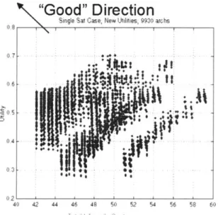
This allows for a discussion with the stakeholders as to what is important to consider in the design. Requirements of safety, speed, repeatability, reliability, cost, weight, and user intractability can all be assigned certain utility values that can be combined. Figure 15 is an example of a dense Tradespace exploration, where emergent patterns start to form as a function of different families of solutions. Figure
15 shows an example of a Tradespace exploration for selecting satellite propulsion candidates from 9930
possible different solutions [20].
"Good" Direction
Single Sat Case, New Utilties, 9930 archs
07
-0.6
-
'~.AP
g
023
40 42 44 46 48 50 52 54 56 58 60
Total LiftcW dp Co-I
Figure 15 -Tradespace example 1191
100% Management Leverage cost Committed KnoWledge Cost Incurred
Concept Detail Production Uise
Development Design
Figure 16 -Value Depiction SEARI [21]
MATE can be used to help guide the make versus buy decision guided by principles established by
Whitney and Fine [22]. Once utility functions were established into an aggregate utility, the Tradespace
analysis can be made. De Neufville has eluded that the Keeney Raiffa's Multi-Attribute utility could capture internal trade-offs performed by the decision maker regarding cost, weight, and performance [19]. Lenze is in a unique position because they have traditionally produced their own test equipment using the resources in house. In the middle of the internship a decision was made to move forward for all new designs with a purchased test system from Germany.
All research efforts were then focused towards improving existing test fixtures. Figure 17 shows how the
research was focused in reference to the German test fixture solution. For all the new products that were in the pipeline, test systems would be purchased.
4--- -- -- -- -- -- -
-M~ngMLenze
Figure 17: Focus of Research Efforts
Lenze has specific needs, the Tradespace analysis takes this into consideration by aggregating the attributes. Hundreds of test fixtures are still used that have 5 or more years of age. An upgrade strategy can be implemented instead of purchasing newer test systems, and paying to remanufacture the test architecture. Where they can still use the existing fixtures, and use commercially available systems going forward. Using MATE a comprehensive list of solutions was evaluated from mechanical, vacuum assisted and automatic systems.
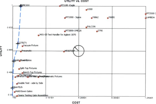
Tradespace analysis conducted using Trade Space Visualizer software from the Applied Research
Laboratory at Penn State applied to the analysis of Make vs. Buy for Electronic Board Test. DMCXXX is coded for the designed system by the author. These visualizations help drive the decision that for Lenze with its current attributes the build option is appealing. The direction vector in the middle points to the highest function and lowest cost solution. The utility function for all attributes is normalized from 0-> 1, with each cost estimate to implement the solution.
0 0 0 UTILITY vs. COST XMTS1M -FAle gulOOO
IMTS300
-Sig O T2 *TE 55*Ml34-1 Test Hander for Agilent 3070
/71 O .Vw__r Fixture
*bpeit-Top Fxtures
ArxFixtures
obtile Test -side by Side
AenTEch
oDown Gates
7W 3 181E4 e 288E4 9 394E4
COST
Figure 18: Purchased vs. Design Tradespace with Pareto Frontier.
Design Manufacture COST z
0 25 0 13 710 1.25E5 3 9
Est Reliabiliy Safety Repeatabilty Cycle Te
UTILITY N Max
0.33 1 0 0 6
MTs50O C
pAMBDA
250EI
Figure 19: Tradespace Attribute Comparison histogram.
The analysis of the Tradespace demonstrates a method in which decisions can be based. Defining a Pareto
Front (PF) as "the state space that has reached the point where an improvement on an individual
selection is impossible without making another one worse". In the TradeSpace above, the PF is located
at the edge of the points that are located farthest away by the direction vector. The Pareto front quickly
shows which purchased solution can be selected based upon attributes that are specific to Lenze's needs
(Figure 18). There are two important aspects of making decisions that should also be discussed. This histogram shows where the DMCXXX option lies in comparison with different attributes (Figure 19); this provides a quick visual snapshot of the performance of one selected solution versus others. The estimate
for the MATE process of DMXXX values is done via best estimates, and function models. Cycle time estimates are based upon testing the prototype fixture methods versus existing, and reported cycle time from vendors. Every effort is made to generate realistic values in respect to the attributes. Research has shown that the marriage of an auditor to an attribute value is biased and that two different auditors will not objectively weight each attribute evenly [19]. An example can be made where a supervisor might weight safety and cycle time differently than the design engineer might weight size, and repeatability. The combined utility of the DMCXXX, is comparable with a system that is roughly 5X the cost per unit. This is the difference from designing to an exact specification, and not having the profit margin requirement.
5.
Design Concept
"It should be simple, to ease maintenance." Nick De Wolf - Terradyne
The focus of this design concept is in upgrading the receiver and fixture connection to the UUT. This keeps intact the decoupled architecture and allows the company to use any solution for the
instrumentation that they want, while not having to incur the cost of new receivers and fixture for each setup.
Given the functional requirements (FR) of the PCB during the test, a system was designed to meet each FR. The goal is of the project was to introduce a system option that satisfies the needs of Lenze and is cost appropriate for the functions delivered.
The functional requirements made selection of design concepts straight forward. There are only so many ways that you can fixture a PCB on a board, and lot of variants of the different strategies:
Vacuum Assisted Mechanical Clamp
* Bottom * Clamshell
* Double Sided * Vertical Press
e Bi-Stable Clamp
From the Digital Test website the following statements address thes6 different strategies: "A large part of
the cost of testing PCBs is the test fixtures. Vacuum fixtures are expensive and double-sided vacuum fixtures are even more expensive. "Press down "fixtures are less expensive because they do not require fixture kits that have to provide a vacuum seal." From the product information page for the MTS 180"
-Eagle [23]
The selected design concept, removed the mechanical clamps from each fixture, and then upgraded the fixtures to be received into a test station. A vertically guided servo actuated clamp and receiver docking station is the employed strategy. Prior work had been done researching this method at Lenze, so it would be lower risk for acceptance.
6.
Functional Requirements and System Design
FR's were created through interviews with operators and engineers from EBT, and through multiple different experiments and analysis of the hundreds of testing fixtures at Lenze. One experiment was done with the guide pins from Misumi and a fixture prototype. After manufacturing the test apparatus, a PCB was placed on the pins, and analysis was done to understand the repeatability and alignment of the PCB. Feedback from the group was very positive. This method while improved using exact constraint required a vertical, planar actuation of the PCB to the POGO pins.
While there are hundreds of test fixtures in existence for every product that needs to be tested, work was done to classify each into family of fixtures. Out of this analysis it was discovered that there were four classes of fixtures in use at Lenze.
1. CNC machined location for POGO
2. PCB test board with soldered POGO
3. Vacuum-Assisted ICT fixtures
4. Hand built, and hand wired fixtures for the larger older products.
Using engineering design concepts of design for manufacturing, assembly engineering, and exact constraint the following FR's were created.
Functional Requirements
1. UUT held flat once placed onto guide pins.
2. UUT will be exactly constrained and have no DOF available when resting on guide pins.
3. Bottom POGO pin positional error will be 0.025" or less with respect to the UUT.
4. The Top mounted pushers:
a. Positional error will be within 0.050" or less.
b. Planar Tolerance Zone will be 0.025" or less.
5. When vertical clamping is made; only 1 vertical DOF is allowed by guide pins.
6. When the Clamping is conducted the PCB will be supported in multiple locations and out
of plane strains will be limited.
7. Minimal effort from the operator is required to actuate the clamping system.
8. When clamping is conducted no force will be exerted on any active component of the
PCB.
9. The PCB will be displaced enough to ensure connectivity with all POGO, all POGO will
be set at the same initial height.
10. Any system designed would be upgradable to the future state production system as
dictated by Lenze Engineering.
11. Operator variability will be minimized.
12. No significant changes to the existing PCB test board architecture will be required.
13. POGO's will be protected during, and after use.
14. When operators change a fixture and replace with another fixture; repeatability will be within 0.0 10" from fixture to fixture.
There exist countless different solutions to these requirements. Engineers have been known to use innovative methods to try and understand as many options as possible using decision matrices, ideation sessions, concept generating matrix, concept prototypes, sketches, scenarios, Role-Play ideation and others [24]. In the end a system that was modular that could accept the existing fixtures and future fixtures requirements using the same PCB design methods was sought. A strategy of user centric design was used to understand what was required of the operator, and to design a system that could improve these methods. Prototypes were made out of cardboard, and user interviews were conducted with the operators of varying heights and body types.
Ideal Method of technician performing a test 1. Place UUT on exact constraint guide pins
2. Push a safety circuit enabled button to engage the clamp and press the PCB into the POGO test points.
3. Test is conducted automatically 4. Push a button to disengage the clamp
5. Remove the UUT and repeat
Although the functional requirements do not call for this, a method of operation in the manner requires a lower amount of operator involvement, and increases the reliability. Having a servo controlled axis of motion would allow the design to achieve later upgradability to an automatic operation where the operator could be decoupled from the operation with the use of in-line conveyors.
Systems that accomplish this are present in the ATE industry, and two that are interesting to note are the Terradyne Test Station series is over $150,000 when fully setup for testing. Not including the inline conveyors used for the material handling. The design parameters must be selected so that all of the functional requirements can be met and still be less expensive and easier than a commercially available solution.
6.1. Exact constraint of the UUT:
"It must be reproducible. If several sets are built, they MUST read the same thing, even if it
involves a loss in overall absolute accuracy." Nick De Wolf - Terradyne
The purpose of this section is to discuss exact constraint methods of fixturing the UUT. The use of complaint guide pins is central to the entire design concept and is a new paradigm for Lenze. Investigating the current mechanical fixturing methods uncovered a case of over-constraint in the mechanical pins that the UUT rest on. The current design uses four pins that are undersized to allow the PCB to assemble to the fixture in an unknown position within the clearance of the Pin-Hole interfaces. Discussions with design engineering revealed they would like a tolerance of position of 0.010" from the PCB to POGO connection. This is not obtainable with the current design due to over constraint of the guide pins. It would require a fixture to place the pins in the correct position and very tight tolerances between the pin, PCB, and location of the holes in the PCB. In audits with operators it was demonstrated multiple times that the operator could manipulate the test voltages by the manner that they placed the
UUT in the fixture. Great care had to be used when placing the UUT in the fixture to do it repeatability.
The solution was to use the principles of exact constraint and remove degrees-of-freedom (DOF) by limiting motion with constraint devices [25]. Since the PCB is preloaded by gravity, and the holes rest on the taper pin, the equilibrium state creates a pivot line between the two diagonal pins. The only other
requirement is for one of the other pins to support in Z. Depending on the center of gravity and the placement of the board only one pin is ever needed to support in Z. This configuration forces the functional requirement for a parallel actuation, when clamping the PCB.
When the PCB is constrained in space in this manner it has no degrees of freedom, and is secure. Only if the preload of the Misumi pins is overcome with a vertical component force will there be motion, and it will be guiding only in 1-DOF. Once the preload force is overcome at any of the four posts the PCB will displace. Since the four pins are not coupled the PCB will have 3-DOF [Z, ROT X, ROT Y], since the only constraints are the [X, Y, ROTZ] created by the two taper pins. Figure 21 shows a commercially available compliant spring pin. Two of these style pins were modified to create the flat pins (Z
constraint). Figure 20, Figure 22, Figure 23 all show the UUT mounted on compliant fixture guide pins using exact constraint.
Constraint: [XY
PCB Resting on Exact Constraint
Constraint: [Z]
Constraint: [ROT ZI
-Figure 20: Diagram showing the constraining positions of the Fixture Pins
PGPUS PGPU 05.0 04.98 C0 L1Figure 21: Commercially Available Circuit Board Guide Pins [26]
291 P a
g
e Constraint: [Z]... ... ...
Ckrcuit Board Guie Pns ... ... ........... ...t
A:I
Figure 22: Side View of PCB with Exact Constraint
Figure 23: Angled front view of Prototype with Misumi Guide Pins
The placement of the PCB is much faster with this method. The lowest height the PCB can obtain is with the two-hole in the nominal position and in the perfect diameter. There is a functional requirement to actuate in a (Parallel to PCB) vertical motion, and ultimately the final height is created by the servo actuated lead screw. The PCB final position will be dictated by the pusher plate and not by the Misumi guide pins. The guide pins allow the board to be held and any deviations affect the non-sensitive DOF.
6.2. Cantilevered Guide Mechanism
FR: 5 When vertical clamping is made; only 1 vertical DOF is allowed by guide pins
There are solutions on the market that use the clamshell type as mentioned previously. In all of these fixtures the operators must open the clamshell, place a UUT inside, close the lid, and latch the device in the locked position. Vendor supplied cycle time estimates 20 seconds on average to cycle a UUT in and lock the system. A vertical DOF can be achieved with a cantilever guided system to support the tooling plate through the intended range of motion. There are vertically guided systems that have die blocks and have 4 guide posts, similar to the Agilent i 1000 system. Since the requirement is to have a total for of
10-30 lbs., a cantilever system can maintain accuracy over this load. (See appendix 11.3 for Cantilever
moment equations).
6.3. Assembly Design Overview
The purpose of this section is to provide information about the main assemblies that interface together; creating the system. There are three main assemblies: Base Plate, Vertical Slider, and the Test Fixture. Only the Vertical Slider assembly has the ability to move when the rotation of the lead screw is transmitted into linear motion using the AMCE thread drive. Figure 24 shows views of the Base Plate Assembly. This is designed to sit flush to the table and provides the entire datum for the Test Fixture and the Vertical Slider Assembly.
Figure 24: Front and ISO view of Base Plate Assembly
Figure 25: Test Fixture Assembly
The test fixture assembly seen in Figure 25 is designed to upgrade the existing method of electronic test; where the POGO test point is created using a PCB. The handles are used so that the operator can easily set the fixture into place. On the perimeter of the test fixture are commercially available tool steel pins that interface in a kinematic coupling. This allows for the repeatable insertion of many different test
fixtures into the Base Plate Assembly.
Figure 26:
ISO
of Base Plate and Test Fixture AssembledIn Figure 26 both the Base Plate and Test Fixture are assembled. The Test fixture sits nearly flush to the base plate and is in a better position for the operator to place the UUT into the system. It is designed to be later upgradeable with inline conveyors. The dashed lines represent the direction the in line conveyors have access to the system for future upgrades. Figure 27 shows a front view of the removable assembly that interfaces with the PCB.
LTop
Tooling
Plate
Assembly
Figure 27: Front View of the Vertical Slider Assembly
Figure 28:
ISO
of Base Plate, Test Fixture, and Vertical Slider AssembliesThe vertical slide assembly has the two main bearings to provide for the cantilever load. There is a quick change design kinematic coupling and a ball locking system, so that the operator is not required to use tools to remove the top tooling plate assembly. The top tooling plate assembly is keyed to each test fixture. Figure 28 shows the completed assembly ready for actuation by the operator using the two safety touch sensors.
7.
Key Characteristics Definition
The purpose of this section is to cover the key characteristics of the assembly connections. A key characteristics (KC) analysis is important to understand what deviations from nominal will cause significant impact to final cost, performance, or safety of a product. Whitney outlines 3 steps to
engineering the design of an assembly [27]. Since there is natural variation in manufacturing processes, care and effort must be utilized to ensure that the desired function is achieved. The design encompasses a Type-I assembly, where all degrees of freedom are exactly constrained. In a Type-2 assembly this is not the case; type-2 systems are under constrained and require fixtures, or measurements to add the missing constraint.
The informational content of type-i is designed internally with the intent of the delivery of the key characteristics. In Type-2 the information is external to the design intent and thus subject to more variation, but can become very accurate with correct calibration.
Define Key Characteristics
Declare the Assembly
Type 1 or Type 2
Draw a Datun Flow Chain [Check: In Type 2 assemblies, for Each KC the DFC may pass through fixture DefIne Mates (Check: There is a chain of mates
Create Features from one end of the KC to the other.]
DegW
Phis"
.]
Constraint
Ensure that Mates Analysis
Create Proper Phase
Constraint
Check for KC Define an Define
Contacts-Conflict Assembly If they ada
over-Sequence That constraint, then
Prioritize Try Another Builds the DFC & ensure that it
oitig T Asely Makes Mates does not affect
Asselny Before Contacts the DFCs.
Sequence
Add Clearance Terances Varitedon
orWWwen of Each KC to ign
Tolerances on the Mates In Its DFC
Lower Priority KCs
DFC and States of Constraint Are Robust to Allowed
Variations Rdekne Fatri
4P or Clearances Analyze Each DFC
to Ensurethat Its KC
Is Delvered a High *Re"tl TolemnmS
Enough Percent of Try Coordiation the Tkie Try a Type 2 Assenbly
Figure 29: Diagram of Assembly Design Process [271.
Below is a Datum Flow Chain (DFC) for the Test Fixture Base to Top Pusher that makes KC-1. KC-2 is created when the PCB-UUT needs to be aligned with the POGO test points. This is used as a map to understand what mates must occur to deliver the KCs.
Top Plate Z-Slide Top ,..--Pusher LeadKC1
L.ew a-'-'',40.", PCB-UUT
Screw Test Motor Fixture GuideBase Rods PCBUJT
4
Compliant Pins4
PCB-Test Board4
.******c. * POGO Fixture Ref Plate BaseFigure 30: Chains of Delivery for KCs in System

![Figure 7: System Architecture [9]](https://thumb-eu.123doks.com/thumbv2/123doknet/14683100.559688/15.918.194.697.476.751/figure-system-architecture.webp)
![Figure 9: An example of a Bed of Nails Platform [11]](https://thumb-eu.123doks.com/thumbv2/123doknet/14683100.559688/16.918.154.746.608.929/figure-example-bed-nails-platform.webp)
![Figure 13: Depiction of proposed future state PCB manufacturing line [16]](https://thumb-eu.123doks.com/thumbv2/123doknet/14683100.559688/19.918.190.667.713.990/figure-depiction-proposed-future-state-pcb-manufacturing-line.webp)