MITLibraries
Document Services Room 14-0551 77 Massachusetts Avenue Cambridge, MA 02139 Ph: 617.253.5668 Fax: 617.253.1690 Email: docs@mit.eduhttp://libraries. mit edu/docs
DISCLAIMER OF QUALITY
Due to the
condition of the original material, there are unavoidable
flaws in this reproduction.
We
have made every effort possible to
provide you
with the best
copy available. If you are
dissatisfied with
this
product and find it
unusable, please
contact Document
Services
as
soon as possible.Thank
you.
Some pages in the original document contain
Design of a Compact, Lightweight, and Low-Cost Solar Concentrator
by
Gabriel J. Gonzdlez
Submitted to the Department of Mechanical Engineering in Partial Fulfillment of the Requirements for the Degree of
Bachelor of Science
at the
MASSACHUSETTS INSTITUTE OF TECHNOLOGY
February 2004
© 2004 Gabriel J. Gonzalez All rights reserved
The author hereby grants to MIT permission to reproduce and to
distribute publicly paper and electronic copies of this thesis document in whole or in part.
Signature of Author ...
Department of Mechadcal Engieering
February 06, 04
Certified by ...
IAo
Ernesto E. Blanco Adjunct Professor of Mechanical Engineering Thesis Supervisor
Accepted
by...< ...
... ...
Professor Ernest G. Cravalho Chairman, Undergraduate Thesis Committee
A Lo aft .
AIIL15
OF TECHNOLOGY IAACQ-ArJwi i9F.rcz 1 it FFE
Design of a Compact, Lightweight, and Low-Cost Solar Concentrator
by
Gabriel J. Gonzalez
Submitted to the Department of Mechanical Engineering on February 6, 2004 in Partial Fulfillment of the Requirements for the
Degree of Bachelor of Science
Abstract
The objective of this mechanical design project was to improve the current design of large and heavy solar concentrators. The three main design goals were: making the system compact, making the system lightweight, and minimizing expenses. The main approach to achieving these design parameters was to use the plastic film Mylar in its aluminized form to create a paraboloid serving as a solar concentrator. The scope of design was limited to designing and prototyping the solar concentrator, and neglecting to design and prototype the container in which it should be kept while in its compact form. Two designs-the tube design and the rim design-are examined, although the rim design is emphasized because of its advantages over the tube design. The tube design included a bicycle tire tube serving as the structural element of the solar concentrator, while the rim design utilized a bandsaw blade (without teeth) as the structural element of the solar concentrator. The prototype of the rim design proved to work well as a mirror, although further work, such as improving the seal around the rim, must still be done due to the time frame and resources allowed for this project.
Thesis Supervisor: Eesto E. Blanco
Acknowledgements
This thesis project is very special to me because I not only learned about the design of solar concentrators, but I also learned a lot about myself and my capabilities. Completion of this thesis would not have been possible without the invaluable help and support provided to me by
several people---People who I consider friends.
Professor Blanco, you have truly inspired me. Thank you for having confidence in me and teaching me much more than mechanical design. Thank you for teaching me much more than I have learned in any classroom or textbook at MIT, and also for your patience. You went the extra mile in being available when I needed your help. It is people like you who make MIT a much more enjoyable and memorable experience.
I would also like to thank everybody at the Pappalardo Lab, especially Steve Haberek. Steve,
thanks for being so helpful with the welding during crunch time and for sharing your knowledge and humor. To the Pappalardo Lab staff, I admire you for your unmatched abilities in machining, your friendly personalities, and your ability to relate with the students you help so much everyday. Thanks for a 0% let-down rate in my four and a half years at MIT.
To Win Burleson, many thanks for being a genuinely nice guy and lending me a hand on short
notice. Without your help deadlines would not have been met, and my thesis would not have been completed on time.
Two very special people in my life have provided me support 24 hours a day, seven days a week:
Natalia Arzeno and Melissa Gonzalez. Thank you for helping me out at all hours of the day, and for believing in me and keeping me motivated when I was discouraged. Thanks for being great
friends.
Last, but not least, I would like to acknowledge my parents for all they have done for me. Mom and dad-Thanks for reminding me to turn to God when I was frustrated with life. Thank you for never neglecting any of my needs and making sacrifices for me so that I could have some opportunities that you were not blessed with growing up. I love you.
Table of Contents 1 Introduction ... 8 1.1 Motivation. ... 8 1.2 Background ... 9 1.3 Scope of Design ... 1... 0 1.4 Design Goals ... 10
2 Tube Design (Not Implemented) ... 11
3 Rim Design (Implemented) ... 15
3.1 Design Overview. ... 15
3.1.1 Materials ... 18
3.1.2 Flexible Rim ... 19
3.1.3 Sealing the System ... 21
3.1.4 Hinge ... 27
3.1.5 Support Frame ... 29
4 Discussion and Conclusion ... 31
5 Appendices ... 33
5.1 Appendix A (Part Drawings) ... 33
List of Figures
Figure 1: Photograph of the folding structure of the deflated bicycle tire tube structure ... 11
Figure 2: Photograph showing the small amount of space the folded bicycle tire tube occupies within the solar concentrator ... 12
Figure 3: Diagram explaining the bicycle tire tube and solar concentrator dual inflation
mechanism...13
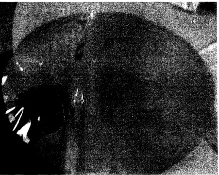
Figure 4: Photograph of fully inflated tube design solar concentrator ... 14
Figure 5: Photograph of solar concentrator apparatus...15
Figure 6:
and being
Photographs describing the process of the compacted solar concentrator opening up
inflated...17
Figure 7: Table including some of Mylar's material properties-Conductivity, specific heat, density, and melting point ... 18
Figure 8: Illustration of compactable Frisbee. Left picture shows the Frisbee in its compact form; Right picture shows the Frisbee in its expanded form ... 19
Figure 9: Top view diagram illustrating the joining of the two ends of the bandsaw blade used to form the rim for the solar concentrator ... 20
Figure 10: Photograph of sealer purchased online (only produces straight seals) ... 22
Figure 12: Left, a diagram of the positioning of materials used to guide the Eurosealer in a
circular path; Right, a photograph of the Eurosealer ... 23
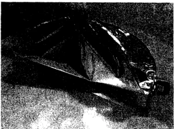
Figure 13: Photographs of two views of solar concentrator sealed using and ultrasonic welding machine ... 26
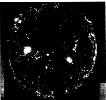
Figure 14: Photograph of inflated solar concentrator showing decent optical quality ... 27
Figure 15: Photograph of the hinge component (front view) ... 28
Figure 16: Photograph of hinge component (top view)...29
Figure 17: Photograph of the support frame made out of aluminum angle ... 30
Figure 18: Comparison of reflection quality between tube design (left) and rim design (right) ... 32
1 Introduction 1.1 Motivation
Satellites have evolved immensely in a little over a third of a century. The launching of a satellite has gone from stopping in a nation's business activities to guaranteeing that they run like
clockwork. Satellites have several applications, such as navigation, communications,
environmental monitoring, and weather forecasting. Everyday life revolves around these services that satellites are making available to humans.
What is a satellite? A satellite is an object that orbits a larger object, such as a planet. Satellites are composed of three main parts:
· communication capabilities with Earth
* a power source
* a control system to accomplish its mission
If any of these three components of satellites were to fail, it would be catastrophic for the mission; therefore, the evolution of power sources for satellites is essential. The most convenient source of energy a satellite could take advantage of is solar energy.
Our planet depends on the Sun as its most important source of energy. Temperatures on the Sun's surface can reach up to about 6000 Kelvin. Nuclear fusion reactions occurring in the Sun's core allow it to produce approximately 386 billion billion megawatts of energy. Man has
created technologies that take advantage of solar energy and transforms it to other forms of energy, such as electric energy.
1.2 Background
The current problem with solar concentrators is that they are large and massive. Professor Ernesto Blanco,, Adjunct Professor of the department of Mechanical Engineering at the Massachusetts Institute of Technology, suggested a design project for one of his classes, "Elements of Mechanical Design": a new design for solar concentrators for satellites. This design project aims to solve the problem of launching large and heavy solar concentrators along with satellites. Blanco's own description of the problem and solution are as follows:
Problem
One of the major problems associated with the use of solar energy is the cost of collectors. In the case of concentrator collectors the problem is even more serious. Besides that, variable focus solar concentrators do not exist. An attempt was made here to produce a concentrator of low cost and reasonably good optical characteristics.
Solution
For most applications where ideal optical characteristics are not essential, a rigid solid surface is hardly justifiable economically. In those cases reflecting films are more attractive. The only problem remaining is the cost of the frame. In the case of the concentrator mirror, the advantages of such a surface could justify the frame cost.
The concept of this film concentrator could not be simpler. A film of reflecting Mylar was attached to a steel dish of flat circular rim although not necessarily well made otherwise. The whole system was well sealed and in between was evacuated with a small vacuum pump. The surface of the taut Mylar film was depressed in a reasonably good optical shape. Only the boundaries showed imperfections. No focal temperatures were measured, but on a clear day wood would burn at the focus almost instantly. The focus could easily be varied by merely changing the pressure differential across the film surface. There may be some applications for this simple approach.
Professor Blanco's goal was to utilize aluminized Mylar to build solar concentrators of decreased
weight and cost.
1.3 Scope of Design
The purpose of this mechanical design project was to design and prototype a solar concentrator for satellites that utilized Mylar as its reflective material. Specifically, this project focused on the design of a compactable solar concentrator, and neglected to design the solar concentrator's compacting container and its positioning system. Also, the solar collector attached to the end of the arm was a mockup made to represent where it would belong in the apparatus.
1.4 Design Goals
The three main design goals were:
· Make the system compactable
· Make the system lightweight
· Minimize expenses
Professor Blanco's idea of using Mylar as the mirror satisfies all three of these goals, but there are several ways in which one could utilize Mylar to make a solar concentrator.
The following describes two different approaches for designing and prototyping a solar concentrator: the tube design and the rim design. Emphasis is placed on the rim design, because that approach achieved better results.
2 Tube Design (Not Implemented)
The first design utilized a bicycle tire tube to create the circular structure of the solar concentrator. By intricately folding the deflated tube, the design goal of making the solar concentrator compact was easily achieved. Preliminary testing included folding the bicycle tire
tube as shown in Figure 1. A rubber band was used to keep the folded tube in its folded position
until the tube was inflated, triggering the rubber band to pop out, which allowed the tube to take its form; consequently, the solar concentrator unfolded and expanded, assuming the circular structure provided by the bicycle tire tube.
Figure 1: Photograph of the folding structure of the deflated bicycle tire tube structure
The large surface area surrounding the deflated bicycle tire tube in its folded state indicates the
solar concentrator's ability of being very compact. Figure 2 makes it clear that the deflated bicycle tire tube accounts for less than 25% of the total solar concentrator surface area. This
Figure 2: Photograph showing the small amount of space the folded bicycle tire tube occupies within the solar concentrator
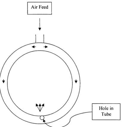
The Presta valve attached to the bicycle tire tube was used to inflate the tube. In order to inflate the solar concentrator, a secondary air feed needed to be included. Keeping with Occam's razor-"Entities must not be multiplied beyond what is necessary"-the tube design was decided to include only one valve to feed air into the system for simplicity. To accomplish this goal, a small hole was punctured in the bicycle tire tube so that as the tube inflated, air would leak into the solar concentrator; consequently, the solar concentrator would also inflate, creating the parabolic shape of the reflecting Mylar film. Figure 3 explains how the dual inflation mechanism works. The hole punctured in the tube was deliberately made small so that the rate of air feed into the bicycle tire tube was greater than the rate of air feed into the solar concentrator. Theoretically, this would prevent air leaking into the solar concentrator at a premature state (i.e. before the bicycle tire tube was inflated enough to fully unfold the
concentrator and provide it structural support). The bicycle tire tube was expected to inflate completely, and at the same time the solar concentrator was expected to slowly inflate until they were both completely inflated and equilibrium was reached.
Air Feed
Figure 3: Diagram explaining the bicycle tire tube and solar concentrator dual inflation mechanism
Figure 4 shows the fully inflated solar concentrator. As can be seen, the optical quality of the Mylar reflecting film is poor. This was partially due to the bicycle tire tube not being rigid enough as a structural element inside the solar concentrator. As a result, the bicycle tire tube did not prevent radial stresses from reaching the area around the concentrator where the two sheets of Mylar were sealed together, causing a peeling effect. Due to the peeling effect, air could not
be pumped into the system to the point where the pressure inside the bicycle tire tube and the pressure inside the solar concentrator would reach equilibrium. The system was not pressurized enough, causing slack and poor optical characteristics.
Figure 4: Photograph of fully inflated tube design solar concentrator
Another drawback to the tube design is that the bicycle tire tube is not rigid enough to support an arm for the focal point. A strong, rigid structural element is required to sustain the moment that an arm would produce.
3 Rim Design (Implemented)
3.1 Design Overview
The rim design apparatus is shown in Figure 5. It includes two sheets of Mylar (one sheet of aluminized Mylar and one sheet of clear Mylar), a flexible rim, a support frame, a spring-loaded hinge, and an arm with the solar collector attached to it. The support frame is the base of the apparatus, on which the solar concentrator sits. The solar concentrator is clamped at both ends-one end is clamped by the spring-loaded hinge, and the other side is clamped with a C-clamp. The solar collector is positioned at the focal point of the paraboloid formed by inflating the solar concentrator. A Presta valve was inserted along the outer edge of the solar concentrator.
The solar concentrator is first folded in half, making it more compact. Then the concentrator is released and it springs open, allowing the arm and collector to also pop up into its position. Air is then pumped into the system through the Presta valve, and a paraboloid mirror/reflector is
5ID
Figure 6: Photographs describing the process of the compacted solar concentrator opening up and being inflated.
The following sections will detail the mechanical components of the rim design.
3.1.1 Materials
Two different types of Mylar were used for the solar concentrator: clear Mylar (.001" thick) and aluminized Mylar (.002" thick). The Gund Company, Inc. describes Mylar as "...a flexible, strong and durable film with an unusual balance of properties making it suitable for many industrial applications. The excellent dielectric strength, moisture resistance and physical toughness make Mylar a very versatile and fully functioning insulating material."
Figure 7 includes some important material properties of Mylar.
Conductivity 0.0016 W/cm K
Specific Heat 1.883 J/g K
Density 1.309 g/cm3
Melting Point 254 C
Figure 7: Table including some of Mylar's material properties-Conductivity, specific heat, density, and melting point
A bandsaw blade was used as the structural element inside the solar concentrator. Welding rod was shaped to make the arm holding the solar collector. The hinge and the support frame were both made out of aluminum.
3.1.2 Flexible Rim
The motivation for using a flexible rim sprouted from a Frisbee design. As Figure 8 shows, the compacted Frisbee on the palm of the hand (left picture) has a wire frame that is twisted a certain way so that it can fit into a small container. Once removed from the container, the Frisbee expands to the size shown in the right picture of Figure 8. The ratio of the expanded form of the
frisbee to the compacted is 3:1.
/~~~~~~~~~~~~~~
£7
Figure 8: Illustration of compactable Frisbee. Left picture shows the Frisbee in its compact form; Right picture shows the Frisbee in its expanded form.
A bandsaw blade was utilized as the rim of the solar concentrator system. As a rough cut, the teeth of the blade were cut off and the remaining material was grinded down using the belt sander to produce a rim 1/8" wide. Both edges of the rim were made smooth so that it would not
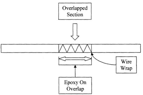
puncture the Mylar in any way, promoting an airtight seal. The two ends of the bandsaw blade were overlapped as shown in Figure 9. In order to conform to the design of a 20" diameter, the length of the overlap was 1.5". The overlap was then wrapped tightly with wire and expoxy was used to bind the two ends of the bandsaw blade together along with the wrapped wire. This proved to be an excellent joint. It could withstand a considerate amount of tension and shear, providing still some flexibility.
Overlapped
Section
I
V~k
~4I
Wire Wrap
Figure 9: Top view diagram illustrating the joining of the two ends of the bandsaw blade used to form the rim for the solar concentrator
Twisting the rim in three dimensions, as the Frisbee approach requires, caused a couple of
problems. The rim showed deformation in its expanded form. Also, twisting the rim in such a manner induced high stresses on the Mylar sheets, which put them in danger of tearing and scratching, causing air leakage and poor optical characteristics.
A compromise was made in the manner of twisting the solar concentrator system in order to prevent any catastrophic events such as tearing and scratching of the Mylar sheets. Bending the rim along one plane worked much better than the previous method of bending the rim along multiple planes (three-dimensional bending). Very little deformation was evident after the solar concentrator was expanded and the stress on the Mylar sheets was significantly lower. As a drawback, the solar concentrator was less compact. The ratio of the expanded form of the solar concentrator to the compact form of the concentrator was 2:1.
3.1.3 Sealing the System
Perhaps the most critical component of the solar concentrator system is the airtight seal it requires. Sealing the system was difficult for a myriad of reasons. For one, the resources available in the short period of time (one month) were few.
The first approach to sealing the system was to use a heat sealer. Local hardware stores did not carry them, so one was purchased from an online company. The purchased heat sealer can be
seen in Figure 10. When first used, it was noted that only straight seals could be made, making it difficult to achieve the goal of creating the circular shape needed for a parabolic concentrator. Figure 11 shows the type of seal actually made by the heat sealer purchased. Not only did the sealer produce an undesired shape, it was also very time consuming. This idea was terminated, due to its insufficiency in achieving design goals.
Figure 10: Photograph of sealer purchased online (only produces straight seals)
Figure 11: Imitation of system sealed by the straight heat sealer
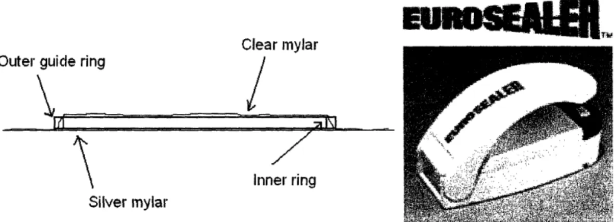
A heat sealer with curved sealing capabilities was sought out. Several expensive heat sealers of this type were found online. The Eurosealer, whose primary function is to seal opened potato chip bags, was selected as the next approach to heat sealing the system. It was capable of making curved seals, and it was much less expensive than the other heat sealers. Minimizing expenses was extremely important, since the budget was tight.
The diagram on the left side in Figure 12 shows the layout of the materials used to facilitate the sealing with the Eurosealer. The aluminized Mylar was placed on the surface of a table. The rim
was then placed over the sheet of aluminized Mylar with the sheet of clear Mylar on top of it. A rim of slightly larger diameter was made (using the same process as the production of the solar concentrator rim). This rim was then placed around the solar concentrator rim, which served two main purposes---it held the two sheets of Mylar closely together, and it also served as a guide for the Eurosealer to follow a circular path.
Outelr guide ring
1E~t
I
- - "M Ar
Clear mylar
Inner ring
Silver mylar
Figure 12: Left, a diagram of the positioning of materials used to guide the Eurosealer in a circular path; Right, a photograph of the Eurosealer
The Eurosealer approach failed in that the seals were too weak, and again, it was time consuming
to use.
Other instruments were tested for their heat sealing capabilities:
· soldering iron
· clothes iron
· hair-straightening iron
· flame from lighter
These approaches all failed to seal the solar concentrator system in a desirable way. The soldering iron and the lighter flame both melted the two sheets of Mylar together. The main problem with these two instruments was that they had little control in the way they sealed because they melted the plastics too quickly. On the other hand, the clothes iron and the
hair-straightening iron had little sealing capability, if any at all.
Ultrasonic welding was the next approach taken. Ultrasonic Metal Welding, a book by STAPLA Ultrasonics Corporation, describes ultrasonic plastic welding:
"Ultrasonic welding of plastics is a state-of-the-art technology that has been in use for many years. When welding thermoplastics, the thermal rise in the bonding area is produced by the absorption of mechanical vibrations, the reflection of the vibrations in the connecting area, and the friction of the surfaces of the parts. The vibrations are introduced vertically. In the contraction area, frictional heat is produced so that material plasticizes locally, forging an insoluble connection between both parts within a very short period of time.
The prerequisite is that both working pieces have a near equivalent melting point. The joint quality is very uniform because the energy transfer and the released internal heat remains constant and is limited to the joining area. In order to obtain an optimum result, the joining areas are prepared to make them suitable for ultrasonic bonding. Besides plastics welding, ultrasonics can also be used to rivet working parts or embed metal parts into plastic."
Limited access was granted for use of the ultrasonic welding machine at the M.I.T. Media Laboratory for the available time frame; therefore, it was assumed that the ultrasonic welder would only be used one time. Figure 13 shows two different views of the same solar concentrator sealed using the ultrasonic welding machine. The ultrasonic welding machine
allowed for the option between two different types of seals. One type of seal was thin and it cut the excess Mylar material simultaneous to the sealing. The other type of seal was a double seal.
The inner seal was a strong, thick seal and the outer seal was the same as the thin seal previously
mentioned. The inner seal was not airtight, but acted as a reinforcement element, preventing the
thin seal to peel.
Unfortunately, the time frame allowed for using the ultrasonic welding machine was too small to master the art of creating an excellent double seal for the solar concentrator. However, the single seal was used and the results were still better than any of the other previous approaches to sealing the system. The process of making the seal included placing the two sheets of Mylar together so that they are flat (without the rim), drawing a circle of 20" diameter (same as the rim)
on one of the sheets, and welding the two sheets together along the drawn circle. A small 4" arc
length was left unsealed, at which point we inserted the rim by bending it until it fit in the open area. The unsealed area was then sealed with the ultrasonic welding machine. As shown in Figure 13, the two Mylar sheets were welded together and fit tightly against the rim.
Figure 13: Photographs of two views of solar concentrator sealed using and ultrasonic welding machine
Epoxy was spread along the outer edge of the welded sheets of Mylar. This was done in order to cover up any small holes that may be present due to bad welding. Also, adding epoxy reinforced the weld. A Presta valve was attached to the outer edge of the solar concentrator by cutting out a small hole on the Mylar. The hole was just big enough to squeeze a third of the Presta valve inside the solar concentrator, and was placed at an angle to the rim, rather than perpendicular to
it. The Presta valve was sealed to the Mylar sheets by adding Epoxy to fill in the gap. The seal
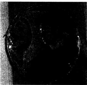
was tested by inflating the solar concentrator by connecting the Presta valve to a bicycle pump fitting. Once fully inflated, the solar concentrator produced a decent mirror, as Figure 14 shows. The solar concentrator slowly deflated, indicating a flaw in the seal. The ultrasonic welding did show a great improvement over previous methods of sealing the system; not only did the interval
between full inflation and full deflation increase, but the seal was able to withstand a higher
Figure 14: Photograph of inflated solar concentrator showing decent optical quality
The quality of the reflection in Figure 14 would have been even better had the aluminized Mylar been kept in better condition prior to the sealing.
3.1.4 Hinge
The hinge component (Figure 15) served both as a clamp for the solar concentrator rim, and as a pivot for the arm supporting the focus point (solar collector). It was made out of sheet aluminum 1/16" thick. The sheet aluminum was clamped and hammered into a 'U' shape, leaving a middle gap of about 1/8" width. Two holes were drilled using the drill press and 10-32 bolts were inserted. As the nuts and bolts were tightened, the two sides of the 'U' slowly closed together, causing a clamping effect on the portion of the solar concentrator rim that was inserted in the
Figure 15: Photograph of the hinge component (front view)
The top view of the hinge component is shown in Figure 16. In this photograph, the pivot and spring mechanism is shown. A plastic tube of diameter slightly larger than that of the welding rod (used for the arm that supports the focus point) was cut and wrapped with wire to prevent it from cracking. Two small holes were drilled on the bottom part of the 'U'. One on each side of the plastic tube, and in each of the holes a leg of a torsion spring is inserted. The two torsion springs can be seen in Figure 16. These torsion springs offered a resistance when it was attempted to close the arm (pivot it so that the focus point gets closer to the solar concentrator). The tube was attached to the hinge component with epoxy. Welding rod was used as the material for the arm.
Figure 16: Photograph of hinge component (top view)
First, the welding rod was inserted through the tube. Then short welding rod protrusions were spot welded onto the inserted welding rod piece in a way so that the welding rod could pivot, but not slide out of the pivot. Also, the protrusions intersected with the free legs of the torsion springs, which provided resistance as mentioned above.
3.1.5 Support Frame
It was noted that the moment acting on the rim as the arm was forced closer to the solar concentrator would cause the rim to bend inward. In order to prevent this from happening, a support frame was built. Aluminum angle was used to build the support frame. It was cut into 3 pieces: 2 pieces that were 3.5" long and one piece that was 20" long. The ends of the pieces
Figure 17: Photograph of the support frame made out of aluminum angle
Another element was welded to the top of one of the sides of the support frame. This plate was 1/8" thick aluminum, and its other dimensions were 3" X 1.5". Two holes were drilled on this plate that matched the holes of the hinge component. The purpose of this was to allow for easy attachment of the hinge to the plate. A clamp on the opposite end was later added in order to stabilize the system.
4 Discussion and Conclusion
The tube design seemed to be a great idea theoretically, but after building a prototype of the design, it was found to be ineffective. The bicycle tire tube was not rigid enough to act as a key structural element. As a result, peeling occurred, and the solar concentrator could not be inflated to the point of equilibrium between the pressure inside of the bicycle tire tube and the pressure inside of the solar concentrator.
The rim design worked great utilizing a bandsaw blade (without teeth) as its structural element. The rim helped ease the radial stresses that the seal would otherwise have to completely incur. Bending of the rim made it less compact than the tube design was able to achieve, but it was still significant with a 2 to 1 ratio of fully expanded solar concentrator to compacted solar
concentrator.
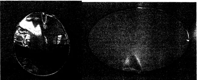
Figure 18 shows the difference in optical quality between the tube design and the rim design. It is evident that the rim design achieved a higher quality of reflection.
Figure 18: Comparison of reflection quality between tube design (left) and rim design (right)
This project still needs further work, due to the time frame and resources available.
It is suggested to attempt a sewing approach to sealing the system. Hand sewing around the rim could provide a strong bond between the two sheets of Mylar. Once sewn, the tiny holes created
by the sewing could be sealed with Krazy glue or epoxy.
Another improvement that could be made is using the material Kapton instead of Mylar. Kapton may be a better option than Mylar because of it degrading less with UV radiation. Properties of
5 Appendices
5.1 Appendix A (Drawings)
(Provided by DuPont)
Mylar®
polyester film
Introduction to Mylar® Polyester Films
Mylar® is a biaxially oriented, thermoplastic film made from ethylene glycol and dimethyl terephtha-late (DMT).
Since DuPont first introduced Mylar® polyester film in the early 1950s, it has been used in a variety of applications that add value to products found in virtually all segments of the world economy. After more than 40 years, the future still holds great promise for Mylar®. Its excellent balance of proper-ties and extraordinary range of performance capa-bilities make Mylar® ideal for a broad array of applications in the electrical/electronics, magnetic media, industrial specialty, imaging/graphics, and packaging markets.
Equally important to the versatility of Mylar® is its environmental friendliness. It is one of the most environmentally safe polymer products made today. Mylar® polyester film, only by DuPont Teijin Films, is available uncoated or coated and in a broad variety of gauges and widths. We are committed to continually developing and improving our product offering. If you have an idea or a special need for a new film, we're ready to explore the possibilities. Just speak with your DuPont Teijin Films sales representative or give us a call at (800) 635-4639.
Balance of Properties
Mylar® polyester films have a unique combination of physical, chemical, thermal, and optical properties:
* Strong, tough, brilliant, and clear. * Ease of converting:
laminating, extrusion coating, embossing, metal-lizing, printing, punching, corrugation, dyeing, stamping or forming.
* Ease of handling on high-speed equipment. * Retain mechanical properties:
stiffness, strength, toughness, dimensional stability, and optical clarity, over an exceedingly wide range of temperatures.
* Excellent temperature resistance. * Readily combined with other materials. * Strong tear-initiation and puncture resistance. * Excellent oil, grease, or moisture barrier
resistance.
* Excellent chemical resistance.
5.2 Appendix
How
Mylar
® Is Made (Figure 1) frame, where it is pulled at right angles (TD* Molten polyethylene terephthalate (PET) polymer orientation). This stretching rearranges the PET is first extruded onto a chill roll drum to form a molecules into an orderly structure to
substan-film. O tially improve the film's mechanical properties.
(Films stretched in the machine direction only are * This film then is biaxially oriented by being uniaxially orented; films stretched in both
stretched first in the machine direction (MD) 0 directions are biaxially orented.) and then in the transverse direction (TD).
* Finally, the film is heat-set 0 to stabilize it. It
* The is accomplished by passing the orientation will not shrink again until exposed to its original film over rollers O that run at increasingly faster heat-set temperature.
speeds (MD orientation), then fed into a tenter
Figure 1. A Typical Manufacturing Process for Oriented Polyester Film
DuPont Teijin Films
1 Discovery Drive (P.O. Box 411) Hopewell, VA 23860 USA Product Information: (800) 635-4639 Fax: 804-530-9867 EG E PET ~N 'UP
0
0
_c ,P I A 0 \ 0 v'I.I
Mylar®
polyester film
Physical-Thermal Properties
My]ar®polyester film retains good physical proper-ties over a wide temperature range (-70 to 150°C [-94 to 302°F]), and it is also used at temperatures from -25() to 200°C (-418 to 392°F) when the physical requirements are not as demanding.
Some physical and thermal properties of Mylar® are summarized in Table 1. Detailed information and other physical and thermal properties are described in the remaining pages of this bulletin.
Table 1
Typical Physical and Thermal Properties of Mylar® Polyester Film
Property Typical Value Unit Test Method Gauge and Type 92A
End Use Industrial
Ultimate Tensile
Strength, MD 20 (29) kg/mm2 (kpsi) ASTM D 882
TD 24 (34)
Strength at 5%
Elongation (F-5), MD 10 (15) kg/mm2 (kpsi) ASTM D 882
TD 10 (14)
Modulus, MD 490 (710) kg/mm2(kpsi) ASTM D 882
TD 510 (740) Elongation, MD 116 % ASTM D 882 TD 91 Surface Roughness Ra 38 nm Optical profilometer Density 1.390 g/cm3 ASTM D 1505 Viscosity 0.56 ASTM D 2857 Melt Point 254 °C DSC* Dimensional Stability at 105C (221°F), MD 0.6 % DuPont test TD 0.9 at 150°C (302°F), MD 1.8 TD 1.1
Specific Heat 0.28 cal/g/°C
Coefficients of
Thermal Expansion 1.7 x 10- 5 in/in/°C ASTM D 696
Thermal Conductivity 3.7 x 10⁻⁴
cal-cm 30-50°C (86-122°F)
(Mylar 1000A) cmZ sec.°C 25-75°C (77-167°F)
Tensile Properties
Figure 1 shows typical stress-strain curves for
Mylar® polyester film at various temperatures. Poisson's ratio is typically 0.38 before yield and 0.58 after yield.
Figure 1. Stress-Strain Curves
Temperature affects the tensile properties of Mylar®; data on a typical sample are shown in
Figure 2. When considering the use of Mylar® at
high temperatures, reference should be made to the last five pages of this bulletin.
Figure 2. Tensile Properties vs. Temperature
1,000,000 0. a 0 LL CD F) i-100,000 10,000 1,000 100 -100 -50 0 50 100 150 200 250 300 (-148) (-58) (32) (122) (212) (302) (392) (482) (572) Temperature, C (°F) Compressive Properties
Compression tests provide information about the compressive properties of plastics when employed under relatively low uniform rates of uniaxially applied loading. Data on the compressive properties of Mylar® polyester film were obtained in accor-dance with ASTM D 695, except that a cylindrical pile of pieces 1 in high, I in in diameter, was used. The data are summarized in Table 2.
When loaded in compression, Mylar® did not exhibit a yield point nor did it fail in compression by a shattering fracture. Therefore, it would be inappropriate to report any value as a compressive strength. However, the stress at 2% deformation and the stress at 1% offset have been calculated. Because the latter stress occurs at very nearly the point where the stress-strain curve begins to deviate markedly from the initial relatively linear portion, it is probably a meaningful upper limit for any application where Mylar® is loaded in compression.
Shear Strength
Mylar® has a shear strength that is significantly higher than published data for other polymeric materials such as acetals, nylons, and polyolefins. Shear strength was measured by a punch-type of test according to ASTM D 732 and is reported in the pounds of force to shear divided by the product of the circumference and the thickness. These tests showed that 5 and 10 mil Mylar® films have shear strengths of 15.0 (21.5) and 13.6 (19.5) kg/mm2 (kpsi), respectively.
Dimensional Stability
The main factors affecting dimensional stability of film are strain relief, thermal expansion, hygro-scopic expansion, and creep. Typical values for these factors are described on following pages.
Strain Relief
Strain relief (also called residual shrinkage) occurs when a film is heated to an elevated temperature. The resulting shrinkage of the film is merely a relaxation of strains induced during the manufac-ture of the film or during processing of the film. Once these strains are relieved at a specific tem-perature, there should be no further shrinkage due to strain relief as long as that temperature is not reached. nnn ~OiVU 30,000 ' 25,000 U 20,000 0 LLC C 15,000 i.7 l 10,000 5,000 n 2,000 - C-00 i 500 P 1,000 XI Q 500 Ax 0 20 40 60 80 100 120 140 Elongation, %
Table 2
Compressive Properties of Mylar® Polyester Film
Maximum
Compressive Stress, 1% Offset Maximum Stress Strain Modulus, kg/mm 2(kpsi) at Stress, During Test, During Test, Film Type kg/mm2 (kpsi) 2% Deformation kg/mm 2(kpsi) kg/mm2 (kpsi) %
Mylar® 1000A 289 (413) 5.91 (8.45) 11.8 (16.8) 21 (30) 23
Mylar® 1400A 278 (397) 5.76 (8.23) 11.6 (16.6) 21 (30) 27
Some typical curves of shrinkage due to strain relief are shown in Figures 3 and 4 for two types of Mylar® polyester film.
Figure 3. Shrinkage vs. Temperature-Mylar 92A
12 10 ax ._ 8 6 4 2 0 20 40 60 80 100 120 140 160 180 200 220 (68) (104) (140) (176) (212) (248) (284) (320) (356) (392) (428) Temperature, °C (F)
Figure 4. Shrinkage vs. Temperature-Mylar® 750A
I -<I IL 10 - 8 4 2 0 c 6 ._ c 4 2 20 40 60 80 100 120 140 160 180 200 220 (68) (104) (140) (176) (212) (248) (284) (320) (356) (392) (428) Temperature, °C (F) Thermal Expansion
The thermal coefficient of linear expansion of Mylar® is 1.7 x 10⁻⁵ in/in/°C (9.5 x 10⁻⁶in/in/°F). As a guide to estimating changes due to thermal expansion, Figure 5 gives the dimensional changes (in/in) over a wide temperature range. Multiplying the indicated change by the sample length gives the thermal dimensional change in the sheet of Mylar®.
Figure 5. Dimensional Stability vs. Temperature Changes 40 30 0 X C-_ co ., N (n 20 10 0 -10 -20 -30 -40 -40 (-40) -34 -29 -23 -18 -12 -7 -1 (-30) (-20) (-10) (0) (10) (20) (30) Change in Temperature, °C (F) 4 (40) Hygroscopic Expansion
The hygroscopic coefficient of linear expansion is 0.6 x 10' in/in/% RH for Mylar® polyester film. The dimensional change due to hygroscopic expansion over a wide range of humidities is shown in Figure 6. To calculate the total dimen-sional change in a sheet of Mylar® due to hygro-scopic expansion, multiply the indicated change by the linear dimensions of the sheet. Under normal atmospheric conditions, changes in thermal expan-sion tend to compensate for changes in hygroscopic expansion because rising temperatures usually
Figure 6. Dimensional Stability vs. Relative Humidity Changes 0 x a C >< a C -a) U,N 0n 45 30 15 0 -15 -30 -40 -30 -20 -10 0 10 20 30
Change in Relative Humidity, %
40
Creep
Mylar® is unusually resistant to creep. Two values measured at room temperature are 0.1% after 260 hr at 2.09 kg/mm2(2.98 kpsi) and 0.2% after
1000 hr at 2.10 kg/mm2(3.00 kpsi). After 4000 hr at 0.35 kg/mm2 (0.50 kpsi) in 100°C (212°F) oven,
a creep of 0.9% was measured.
Hydrolytic Stability
Mylar® polyester film will hydrolyze and become brittle under conditions of high temperature and humidity, as shown by the effect of steam on the tensile properties of Mylar® (Figures 7, 8, and 9). Therefore, care should be taken to ensure that there is a minimum of water in any hermetically sealed unit. Adequate removal of water from Mylar is usually obtained by heating for 4 hr at 160°C
Figure 7. Tensile Strength of Mylar® after Exposure
to Steam 25,000 20,000
i
,m C, O02
cm a) I-1 5,000 0,000 5,000 0 0 250 500 750(320°F). (Drying at these conditions should reduce the water content of the film to less than 0.1%; more than this amount of water must be present in a system before the film can become embrittled due to hydrolysis.) Drying at lower temperatures is not as effective in removing water as shown in Figure
10. Data for this figure were obtained with samples
of Mylar 1000IA conditioned for one month at 22°C (72°F) and 80% RH and then dried under vacuum for 4 hr at the indicated temperatures.
Figure 8. Tensile Elongation of Mylar® after Expo-sure to Steam 250 200 c -0 ._ c 0) a C CD i-150 100 50 0 0 250 500 Time, hr in 100°C (212°F) Steam 750
Figure 9. Tensile Modulus of Mylar® after Exposure to Steam 600,000 500,000 . 400,000 o 300,000 i 200,000 100,000 0 0 250 500 750 i A r _ _
Figure 10. Effect of Temperature on the Removal of Water from Mylar'
0.8 0.6 0.4 0.2 0 40 80 120 160 (3;2) (104) (176) (248) (320) Temperature, °C (F) 200 (392) 220 (428)
Figure 11. Tensile Strength of Mylar® after Heating in 150°C (302°F) Air 25,000 0. L 4e cm F-._ax 0 20,000 15,000 10,000 5,000 0 0 1,000 2,000 3,000 4,000 5,000 Time, hr at 150°C (302°F) Heat Aging
The maximum service temperature usually recom-mended for Mylar® polyester film is 150°C
(302°F). Where extensive exposure, severe environ-mental conditions, or unusual physical require-ments are involved, it may be necessary to reduce service temperatures. However, coatings are available to increase the resistance of Mylar® to the effects of heat aging. The effects of heat aging on uncoated Mylar® in 150°C (302°F) air are shown in
Figures 11 and 12.
Processing conditions for Mylar® should be kept below 200'C (392°F) to prevent damaging the film. For instance, if heated at 220°C (428°F) for 30 min, the film loses about 10% of its tensile strength; moreover, the film becomes brittle and shatters after heating at 235°C (455°F) for less than 1 min.
Figure 12. Tensile Elongation of Mylar® after Heating in 150°C (302°F) Air 200 == o a) .2_I-a) 150 100 50 0 0 1,000 2,000 3,000 4,000 5,000 Time, hr at 150°C (302°F) E 0._= a.> 4'D> oL EV iZ a) cc
[
I I I I I I I I I I I I I I I I I ' I I - -A..Service Life
The service life of Mylar®, when subject to severe flexing, is considered to be the time required to reach 10% elongation under various conditions of humidity and operating temperature. The curves shown in Figure 13 are based upon tests of Mylar® 92 and 1000A at various partial pressures of water. The estimated service life will be greater when the film is suitably encapsulated or coated. Longer life can also be expected when the Mylar® is not subject to flexing.
Figure 13. Effect of the Partial Pressure of Water on Service Life 50 40 .- 30 0 20 i: c - 10 8 t0 7 - 6
04
0 3 4. a) . 2 I-1 2 3 4 5 678910 Partial Pressure o IEquivalent Atmospheric Conditions 22°C{7 (Continuous Exposure) and 50°
20 30 4050 60 80100
I I
,f Water, mmHg
2°F) 22°C 72F) 38&C I11tF) 6 RH and 100% RH and 00% RH
Note: These values are typical performance data for Mylar® polyester film; they are not intended to be used as design data. We believe this information is the best currently available on the subject. It is offered as a possible helpful suggestion in experimentation you may care to undertake along these lines. It is subject to revision as additional knowledge and experience is gained. DuPont Teijin Films makes no guarantee of results and assumes no obligation or liability whatsoever in connection with this information. This publication is not a license to operate under, or intended to suggest infringement of, any existing patents.
DuPont Teijin Films
I Discovery Drive (P.O. Box 411) Hopewell, VA 23860 Product Information: (800) 635-4639 Fax: (804) 530-9867
Mylar®
(06/20)03) 222367D Printed in U.S.A. H-37232-21 --Permeability
Mylar® polyester film is virtually impermeable to the liquid phase of most chemicals and reagents. The permeability of Mylar® to the vapor phase of some typical chemicals is shown in Table 4. The effect of film thickness on the rate of water vapor transmission through Mylar® is shown in Figure 1. Gas permeability rates are shown in Table 4 and
Figure 2. Marked reductions in gas permeability
(up to a factor of 100) can be obtained through polymeric coatings, metal foil laminations, or vacuum metallization.
Table 4
Permeability of MylarO to Gases and Vapors
Vapors g/100 in2/24 hr/mil* Acetone 2.22 Benzene 0.36 Carbon Tetrachloride 0.08 Ethyl Acetate 0.08 Hexane 0.12 cc/100 in2/
Gas Temp., °C (°F) 24 hr/atm/mil Test Method
Carbon Dioxide 25(77) 16 ASTM D1434-58
Freon® 12 55(131) 0.01
Methane 25(77) 1
*Permeabilities of vapors are determined at the vapor pressure of the
liquid at the temperature of the test, 40°C (104°F), using 1 mil film.
Figure 2. Gas Permeability of Mylar evs. Temperature
_ ._ E v X Ne N C 0 0 0 Nc ._M Ea) 0 0._ XD I UUUUU80uu,u00 80,000 60,000 40,000 20,000 10,000 6,000 4,000 2,000 1,000 800 600 400 200 100 80 60 40 20 10 8 6 4 2 3.6 inn nnn 3.4 3.2 (32) (77) (122) Temperature, °C
Figure 1. Water Vapor Transmission Rate of Mylar® at 38°C (100°F) (ASTM E-96, Procedure E)
^.U { 2r 1.8 _ 1.6 0 1.4 a 1.2 cc C .° 1.0 en ._ E 0.8 U' Cc _ 0.6 0 Q 0.4 a) 0.2 X n o v u 0 2 4 6 8 10 12
Film Thickness, mil
2000 1500 le N _ ._ o0 0 1000 Z 500 ., 500
Moisture Absorption
Mylar® polyester film is relatively insensitive to moisture absorption. It absorbs less than 0.8% moisture when totally immersed in water for 24 hr (ASTM D-570-63). For sheet samples hanging in
air, with a relative humidity of 80%, the time required to absorb moisture increases as the film thickness increases (see Table 5). The effect of relative humidity on the moisture content of single
sheet samples is shown in Figure 3. (Moisture content was determined by drying at 1000C (212°F) -drying at 150°C (302°F) drives off another 0.2 to
0.3% water.)
For slit rolls of film, the rate of change in moisture content of Mylar® is very slow because of the low moisture permeability of the film. Hence, except for very unusual situations, the moisture content of the film at the time of manufacture will be maintained until processed by the customer.
Table 5
Rate of Moisture Gain of Single Sheets of Mylar®
Time Required to Gain 90% Equilibrium Gauge, mil Moisture Content, min
1/2 15 3.0 2.8 2.6 1167) (°F) (212) L.U I Zbgg i I)
Kapton® polyimide film possesses a unique combination of properties that make it ideal for a variety of applications in many different industries. The ability of Kapton® to maintain its excellent physical, electrical, and mechani-cal properties over a wide temperature range has opened new design and application areas to plastic films.
Kapton® is synthesized by polymerizing an aromatic dianhydride and an aromatic diamine. It has excellent chemical resistance; there are no known organic solvents for the film. Kapton® does not melt or burn as it has the highest UL-94 flammability rating: V-0. The outstanding properties of Kapton® permit it to be used at both high and low temperature extremes where other organic polymeric materials would not be functional.
Adhesives are available for bonding Kapton® to itself and to metals, various paper types, and other films.
Kapton® polyimide film can be used in a variety of electrical and electronic insulation applications: wire and cable tapes, formed coil insulation, substrates for flexible printed circuits, motor slot liners, magnet wire insula-tion, transformer and capacitor insulainsula-tion, magnetic and pressure-sensitive tapes, and tubing. Many of these applications are based
on the excellent balance of electrical, thermal, mechanical, physical, and chemical properties of Kapton® over a wide range of temperatures. It is this combination of useful properties at temperature extremes that makes Kapton® a unique industrial material.
Three types of Kapton® are described in this bulletin:
* Kapton® Type HN, all-polyimide film, has been used successfully in applications at temperatures as low as -269°C (-452°F) and as high as 400°C (752°F).
Type HN film can be laminated, metallized, punched, formed, or adhesive coated. It is
available as 7.5 pm (0.3 mil), 12.5 pm
(0.5 mil), 19 pm (0.75 mil), 25 pm (1 mil), 50 pm (2 mil), 75 pm (3 mil), and 125 pm (5 mil) films.
Kapton® Type VN, all-polyimide film with all of the properties of Type HN, plus superior dimensional stability. Type VN is
available as 12.5 pmrn (0.5 mil), 19 pm (0.75 mil), 25 pm (1 mil), 50 pmrn (2 mil),
75 pm (3 mil), and 125 pm (5 mil) films.
Kapton® Type FN, a Type HN film coated on one or both sides with Teflon® FEP fluoropolymer resin, imparts heat seala-bility, provides a moisture barrier, and enhances chemical resistance. Type FN is available in a number of combinations of polyimide and Teflon® FEP thicknesses
(see Table 16).
Note: In addition to these three types of
Kapton®, films are available with the follow-ing attributes:
* antistat
* thermally conductive
* polyimides for fine line circuitry * cryogenic insulation
* corona resistant * pigmented for color * conformable
* other films tailored to meet customers' needs
Data for these films are covered in separate product bulletins, which can be obtained from your DuPont representative.
The Chemical Abstracts Service Registry Number for Kapton® polyimide film is [25036-53-7].
.I;,'I
7"1'
!a, ~~~~~~~~~~~~~I
4( ".
Kapton~withstands the harsh chemical and physical demands on diaphragms used in automotive switches.
Kapton®is used in numerous electronic applications, including hard disk drives.
I - I- 11
Kapton® polyimide films retain their physical properties over a wide temperature range. They have been used in field applications where the environmental temperatures were as low as -269°C (-452°F) and as high as 400°C (752°F).
Complete data are not available at these extreme conditions, and the majority of techni-cal data presented in this section falls in the 23 to 200°C (73 to 392°F) range.
Table 1
Physical Properties of Kapton® Type 100 HN Film, 25 gm (1 mil)
Typical Value at
Physical Property 23°C (73°F) 200°C (392°F) Test Method
Ultimate Tensile Strength, MPa (psi) 231 (33,500) 139 (20,000) ASTM D-882-91, Method A*
Yield Point at 3%, MPa (psi) 69 (10,000) 41 (6000) ASTM D-882-91
Stress to Produce 5% Elongation, MPa (psi) 90 (13,000) 61 (9000) ASTM D-882-91
Ultimate Elongation, % 72 83 ASTM D-882-91
Tensile Modulus, GPa (psi) 2.5 (370,000) 2.0 (290,000) ASTM D-882-91
Impact Strength, N cm (ft. lb) Folding Endurance (MIT), cycles
Tear Strength-Propagating (Elmendor0, N (Ibf) Tear Strength-Initial (Graves), N (bf)
Density, g/cc or g/mL
78 (0.58) 285,000
0.07 (0.02) 7.2 (1.6)
DuPont Pneumatic Impact Test
ASTM D-2176-89
ASTM D-1922-89
ASTM D-1004-90
1.42 Coefficient of Friction-Kinetic (Film-to-Film)
Coefficient of Friction-Static (Film-to-Film)
Refractive Index (Sodium D Line)
Poisson's Ratio
Low Temperature Flex Life
0.48 0.63 1.70 0.34 Pass ASTM D-1505-90 ASTM D-1894-90 ASTM D-1894-90 ASTM D-542-90
Avg. Three Samples Elongated at 5%, 7%, 10% IPC TM 650, Method 2.6.18
*Specimen Size: 25 x 150 mm (1 x 6 in); Jaw Separation: 100 mm (4 in); Jaw Speed: 50 mm/min (2 in/min); Ultimate refers to the
tensile strength and elongation measured at break.
Table 2
Thermal Properties of Kapton® Type 100 HN Film, 25 pm (1 mil)
Thermal Property Typical Value Test Condition Test Method
Melting Point None None ASTM E-794-85 (1989)
Thermal Coefficient of 20 ppm/°C -14 to 38°C ASTM D-696-91
Linear Expansion (11 ppm/°F) (7 to 100°F)
Coefficient of Thermal Conductivity, ASTM F-433-77 (1987)E1
W/mK 0.12 296 K
cal
cm sec.°C 2.87 x 10" 23°C
Specific Heat, J/g.K (cal/g-°C) 1.09 (0.261) Differential Calorimetry
Flammability 94V-0 UL-94 (2-8-85)
Shrinkage, % 0.17 30 min at 1500C IPC TM 650, Method 2.2.4A
1.25 120 min at 400°C ASTM D-5214-91
Heat Sealability Not Heat Sealable
Limiting Oxygen Index, % 37 ASTM D-2863-87
Solder Float Pass IPC TM 650, Method 2.4.13A
Smoke Generation DM = <1 NBS
Smoke Chamber NFPA-258
Glass Transition Temperature (Tg) A second order transition occurs in Kapton' between 360C (680°F) and 410C (770°F)
and is assumed to be the glass transition temperature. Different measurement
Table 3
Physical and Thermal Properties of Kapton® Type VN Film
Typical Value for Film Thickness
25 m 50 m 75 gm 125 m Test Property (1 mil) (2 mil) (3 mil) (5 mil) Method
Ultimate Tensile Strength, MPa 231 234 231 231 ASTM D-882-91
(psi) (33,500) (34,000) (33,500) (33,500)
Ultimate Elongation, % 72 82 82 82 ASTM D-882-91
Tear Strength-Propagating (Elmendorf), N 0.07 0.21 0.38 0.58 ASTM D-1922-89
Tear Strength-Initial (Graves), N 7.2 16.3 26.3 46.9 ASTM D-1004-90
Folding Endurance (MIT), x 103 cycles 285 55 6 5 ASTM D-2176-89
Density, g/cc or g/mL 1.42 1.42 1.42 1.42 ASTM D-1505-90
Flammability 94V-0 94V-0 94V-0 94V-0 UL-94 (2-8-85)
Shrinkage, %, 30 min at 150°C (302°F) 0.03 0.03 0.03 0.03 IPC TM 650
Method 2.2.4A
Limiting Oxygen Index, % 37 43 46 45 ASTM D-2863-87
Table 4
Physical Properties of Kapton®Type FN Film*
Typical Value for Film Type* *
Property 120FN616 150FN019 250FN029
Ultimate Tensile Strength, MPa (psi)
23°C (73°F) 207 (30,000) 162 (23,500) 200 (29,000)
200°C (392°F) 121 (17,500) 89 (13,000) 115 (17,000)
Yield Point at 3%, MPa (psi)
23°C (73°F) 61 (9000) 49 (7000) 58 (8500)
200°C (392°F) 42 (6000) 43 (6000) 36 (5000)
Stress at 5% Elongation, MPa (psi)
23°C (73°F) 79 (11,500) 65 (9,500) 76 (11,000)
200°C (392°F) 53 (8000) 41 (6000) 48 (7000)
Ultimate Elongation, %
23°C (73°F) 75 70 85
200°C (392°F) 80 75 110
Tensile Modulus, GPa (psi)
23°C (73°F) 2.48 (360,000) 2.28 (330,000) 2.62 (380,000)
200°C (392°F) 1.62 (235,000) 1.14 (165,000) 1.38 (200,000)
Impact Strength at 23°C (73°F),
N-cm (ft lb) 78 (0.58) 68.6 (0.51) 156.8 (1.16) Tear Strength--Propagating (Elmendorf),
N (Ibf) 0.08 (0.02) 0.47 (0.11) 0.57 (0.13)
Tear Strength-Initial (Graves), N (Ibf) 11.8 (2.6) 11.5 (2.6) 17.8 (4.0)
Polyimide, wt% 80 57 73
FEP, wt% 20 43 27
Density, g/cc or g/mL 1.53 1.67 1.57
Test methods for Table 4 are the same as for Table 1.
* *Because a number of combinations of polyimide film and fluorocarbon coating add up to the same total gauge. it is necessary to
distinguish among them. A three-digit system is used in which the middle digit represents the nominal thickness of the base
Kapton' film in mils. The first and third digits represent the nominal thickness of the coating of Teflon" FEP fluoropolymer resin
in mils. The symbol 9 is used to represent 13 gtm (0.5 mil) and 6 to represent 2.5 gm (0.1 mil). Example: 120FN616 is a 120-gauge
The usual values of tensile strength, tensile modulus, and ultimate elongation at various temperatures can be obtained from the typical stress-strain curves shown in Figures I and 2. Such properties as tensile strength and modulus are inversely proportional to temperature,
whereas elongation reaches a maximum value at about 300°C (570°F). Other factors, such as humidity, film thickness, and tensile elongation rates, were found to have only a negligible effect on the shape of the 23°C (73°F) curve.
Figure 1. Tensile Stress-Strain Curves, Type HN Film, 25 gm (1 mil)
0 10 20 30 40 50 60 70 80 90 100 250 200 150 & 0; 100 50 0 Strain-Elongation, %
Figure 2. Tensile Creep Properties, Type HN Film, 25 4m (1 mil)
10 100 Time, min 1000 10,000 36 32 28 24 20 .bg (A U, 16 12 23-C (73°F) 100C (212°F) 200°C (392°F) I I I I I r I I 8 4 0 8 6 4 2 0, LU co CD CT 1 0.8 0.6 _-~~~~~~~ 1 ~00oc (212°F) 61 MPa (8850 psi)
~~~~~~~~-
~26°C
(80
0
F)
~~~~~~~- ~21 MPa (2980 psi) ~~~~~~~~_ ~26°C (80°F) 11 MPa (1610 psi) ~~~~~~~_ ~26C (80°F) 6.5 MPa (950 psi) 0.4 0.2 0 1 _-A _ _ _ _ _ _Kapton®polyimide film is made by a condensa-tion reaccondensa-tion; therefore, its properties are affected by water. Although long-term expo-sure to boiling water, as shown in the curves in
Figures 3 and 4, will reduce the level of film
properties, sufficient tensile and elongation Figure 3. Tensile Strength After Exposure to
25 Am (1 mil) 36 32 28 . .d 0) .. 81 U' 81 24 20 16 12 8 4
remain to ensure good mechanical perfor-mance. A decrease in the temperature and the water content will reduce the rate of Kapton' property reduction, whereas higher temperature and pressure will increase it.
100°C (212°F) Water, Type HN Film,
250 200 X E 150 a 10o ,m0. 2 50 0 0 0.2 0.4 0.6 0.8 1.0 1.2 1.4 1.6 1.8 2.0 2.2 2.4 2.6
Time in Boiling Water x 103 h
Figure 4. Ultimate Elongation 25 gm (1 mil) 100 90 80 70 0 EU 0) 0 LU .o uJ 60 50 40 30 20 10
After Exposure to 100°C (212°F) Water, Type HN Film,
0 0.2 0.4 0.6 0.8 1.0 1.2 1.4 1.6 1.8
Time in Boiling Water x 10 h
2.0 2.2 2.4 2.6 I I I I I I I I I I I I I t I I I I I I I I 0 _ _ _ _ _ _ _ _ _
The dimensional stability of Kapton® polyimide film depends on two factors-the normal coefficient of thermal expansion and the residual stresses placed in the film during manufacture. The latter causes Kapton® to
shrink on its first exposure to elevated tempera-tures as indicated in the bar graph in Figure 5. Once the film has been exposed, the normal values for the thermal coefficient of linear
expansion as shown in Table 5 can be expected.
Figure 5. Residual Shrinkage vs. Exposure Temperature and Thickness, Type HN and VN Films
[ HN (150°C) E VN (200C)* [ HN (400°C) 1.26 II 0.20 50 (2)
Film Thickness, IJm (mil)
*Type VN shrinkage is 0.03% for all thicknesses.
Table 5
Thermal Coefficient of Expansion, Type HN Film, 25 gm (1 mil),
Thermally Exposed Temperature Range, C (F) ppm/°C 30-100 (86-212) 17 100-200 (212-392) 32 200-300 (392-572) 40 300-400 (572-752) 44 30-400 (86-752) 34 1.6 1.4 1.2 1.25 1.47
7
1.0 0.8 0.6 0, (U c co -.9L . I-0.4 0.2 0.23 25 (1) 0.25 75 (3) 125 (5) I I 1- s --I S . S - 0 - E-_1.54 -- I l BThe useful life of Kapton®polyimide film is a function of both temperature and oxygen concentration. In accordance with UL-746B test procedures, the thermal life of Kapton®was
determined at various temperatures. At time zero and 325°C (617°F), the tensile strength is 234 MPa (34,000 psi) and the elongation is 67%. The results are shown in Figures 6-8.
Figure 6. Tensile Strength vs. Aging in Air at 325°C (617°F), Type HN Film, 25 gm (1 mil)
80 a: qa C .t_e, ,m C Ul 20 0 1000 400 600 Time at 325°C (617°F), h
Figure 7. Ultimate Elongation vs. Aging in Air at 325°C (617°F), Type HN Film, 25 gm (1 mil) 100 80-rC 60 C .o-C* 40.-w0 20--20 0 I I I I I 0 200 400 600 800 1000 Time at 325°C (617°F), h 0 200 800 60 40 I'll ii B~ i .I... _ . _ .
Figure 8. Retained Dielectric Strength at 325°C (617°F) for 25 gm (1 mil) Film, Test Method UL-746B
120 100 ._ 4' a, ._ 0, ¢, .o OI a, 80 60 40 20 0 0 500 Time at 325°C (617°F), h 1000
The life of Kapton® polyimide film at high temperature is significantly extended in a low-oxygen environment. Kapton® is subject to oxidative degradation. Hence, when it was tested in a helium environment, its useful life
was at least an order of magnitude greater than in air. Using a DuPont 1090 thermal analyzer system, the weight loss characteristics of Kapton® in air and helium at elevated tempera-tures are shown in Figures 9 and 10.
Figure 9. Weight Loss, Type HN Film, 25 gm (1 mil)*
0 10 -20 _ 30 0 -( 0 40 50 60 70 80 90 100 Dry He Dry Air l I I I I I I 100 (212) 200 300 400 500 600 700 800 900 1000 (392) (572) (752) (930) (1112) (1292) (1472) (1652) (1832) Temperature, C (F)
*Rate of temperature rise in C (F) was 3°Clmin (5.4°F/min).
I I I I I . _ _