Publisher’s version / Version de l'éditeur:
Vous avez des questions? Nous pouvons vous aider. Pour communiquer directement avec un auteur, consultez la première page de la revue dans laquelle son article a été publié afin de trouver ses coordonnées. Si vous n’arrivez pas à les repérer, communiquez avec nous à [email protected].
Questions? Contact the NRC Publications Archive team at
[email protected]. If you wish to email the authors directly, please see the first page of the publication for their contact information.
https://publications-cnrc.canada.ca/fra/droits
L’accès à ce site Web et l’utilisation de son contenu sont assujettis aux conditions présentées dans le site LISEZ CES CONDITIONS ATTENTIVEMENT AVANT D’UTILISER CE SITE WEB.
13th Canadian Conference on Building Science and Technology [Proceedings], 2011-05-09
READ THESE TERMS AND CONDITIONS CAREFULLY BEFORE USING THIS WEBSITE. https://nrc-publications.canada.ca/eng/copyright
NRC Publications Archive Record / Notice des Archives des publications du CNRC :
https://nrc-publications.canada.ca/eng/view/object/?id=28f596a9-fddd-475a-9d8a-8ceddadc1a43 https://publications-cnrc.canada.ca/fra/voir/objet/?id=28f596a9-fddd-475a-9d8a-8ceddadc1a43
NRC Publications Archive
Archives des publications du CNRC
This publication could be one of several versions: author’s original, accepted manuscript or the publisher’s version. / La version de cette publication peut être l’une des suivantes : la version prépublication de l’auteur, la version acceptée du manuscrit ou la version de l’éditeur.
Access and use of this website and the material on it are subject to the Terms and Conditions set forth at
Temperature induced stresses on modified bituminous low-slope roofing systems
Temperature induced stresses
on modified bituminous
low-slope roofing systems
N R C C - 5 4 4 5 9
M o l l e t i , S . ; B a s k a r a n , B . A . ; B e a u l i e u , P .
M A Y 2 0 1 1
A version of this document is published in / Une version de ce document se trouve dans:
13th Canadian Conference on Building Science and Technology, Winnipeg, Manitoba, May 9, 2011
http://www.nrc-cnrc.gc.ca/irc
The material in this document is covered by the provisions of the Copyright Act, by Canadian laws, policies, regulations and international agreements. Such provisions serve to identify the information source and, in specific instances, to prohibit reproduction of materials without written permission. For more information visit http://laws.justice.gc.ca/en/showtdm/cs/C-42
Les renseignements dans ce document sont protégés par la Loi sur le droit d'auteur, par les lois, les politiques et les règlements du Canada et des accords internationaux. Ces dispositions permettent d'identifier la source de l'information et, dans certains cas, d'interdire la copie de documents sans permission écrite. Pour obtenir de plus amples renseignements : http://lois.justice.gc.ca/fr/showtdm/cs/C-42
Page 1 of 12
Temperature Induced Stresses on Modified Bituminous Low-Slope
Roofing Systems
Suda Molletic, Bas Baskaran and Pascal Beaulieu
National Research Council Canada Building Envelope and Structure Program 1200 Montreal Road, Campus-Building M-24 Ottawa, Ontario K1A 0R6,Canada
c
Tel: 613-993-9673,Fax: 613-998-6802,Email: [email protected]
Abstract
In Canada, where the design temperatures are above freezing, the SBS modified bitumen roofing membrane are the most commonly used and are in practice since 1950’s. The modified bituminous roof membrane system is a two-ply system comprising of a base sheet and a cap sheet. Existing literatures on the thermal stresses induced in the modified bitumen systems indicate that these systems have a history of problems such as blistering, rupturing, splitting and slippage, however, with the improvement in the manufacturing process and better system designs, these issues subsided with time. In the recent past, the issue of membrane ridging on low sloped modified bitumen systems was brought to the attention of National Research Council of Canada. Membrane ridging sometimes referred to wrinkling was a common failure mode observed on BUR systems over the past decade, however this seems to be emerging on the two-ply mod-bit systems. However, the question is whether the ridging is the effect of any material or whole system performance. The present paper presents two case studies showing the membrane ridging on two roofs and also discusses a small scale experimental study that was conducted at the National research Council of Canada to understand the thermal induced stresses in modified bituminous roofing systems
Introduction
With the advancement in the roofing technology, the four ply built up membrane has been reduced to two ply bitumen sheets. To make bitumen tougher and more elastic, a synthetic polymer such as atactic polypropylene (APP) and styrene-butadiene-styrene (SBS) is usually added. The resulting mixture is called modified bitumen. Modified bituminous sheets are made by combining the modified bitumen with reinforcements such as glass and polyester fibres. SBS is a rubber-type modifier that gives bitumen the ability to stretch and resist damage, and improves its cold-temperature flexibility. In Canada, where the design temperatures are above freezing, the SBS modified bitumen roofing membrane are the most commonly used.
The modified bituminous roof membrane system is a two-ply system comprising of a base sheet and a cap sheet. The base sheet is the first layer and is installed either over the insulation or cover board. Common modes of attachment of the base sheet is mechanical fastening to the steel deck along its seam using mechanical fasteners and plate as in a mechanically fastened system or it can be adhered to the substrate below as in adhesive applied system. The cap sheet is the top layer and provides the first line of waterproofing defense for the roof system. Its upper surface may be coated with mineral granules or with metal foil to increase the membrane weatherability and UV resistance. The cap sheet is integrated to the base sheet
Page 2 of 12
either by cold adhesive application, torching or by hot moping. Figure 1 shows a typical layout of mechanically fastened and adhesive applied modified bitumen roofing system. As shown in the figure, the five common components with associated functions are:1. Deck - Structural support- 2. Barrier - Air and moisture control - 3. Insulation - Thermal control - 4. Cover board – Protection board - 5. Membrane – Waterproofing - 6. Attachment systems - Integration
The service life of a roof depends on the characteristics (physical, chemical and mechanical properties) of the individual components and the performance of the whole assembly.
FIGURE 1: TYPICAL LAYOUT OF MODIFIED BITUMEN ROOFING SYSTEM
The modified bitumen systems are one of the most common low sloped roofing systems in Canada and are in practice since 1950’s. Existing literature on the thermal stresses induced in the modified bitumen systems (Rossiter and Batts, 1985; Turenne, 1976;Baskaran et.al,2003;Booth,1997) indicate that these systems have a history of problems such as blistering, rupturing, splitting and slippage, however, with the improvement in the manufacturing process and better system designs, these issues subsided with time. In the recent past, the issue of membrane ridging on low sloped modified bitumen systems was brought to the attention of National Research Council of Canada. Membrane ridging sometimes referred to wrinkling was a common failure mode observed on BUR systems over the past decade, however this seems to be emerging on the two-ply mod-bit systems. However, the question is whether the ridging is the effect of any material or whole system performance? The present paper presents two case studies showing the membrane ridging on two roofs and also discusses a small scale experimental study that was conducted at the National research Council of Canada to understand the thermal induced stresses in modified bituminous roofing systems.
Case Study 1: School Roof, Montreal
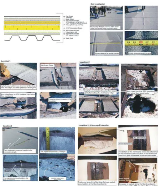
Figure 2 shows the roofing configuration of the investigated school roof in Montreal. As shown in the figure, it had a steel deck as the structural support, 5/8 in. (16mm) gypsum and two ply organic felt as the vapor barrier, 4 ft x 4 ft (1.2m x 1.2m) expanded polystyrene with 4 in. (102mm) thickness acting as the thermal barrier, two ½ in. (12mm) factory bonded ship lapped fiber boards as the protective boards and finally two ply modified bituminous membrane (base and cap sheet) as the waterproofing component. On the construction side, all the components were hot asphalt moped except the cap sheet, which was torched to the base sheet. Essentially it was a hot moped two ply modified- bituminous system.
The roof was two years old and it underwent four seasonal cycles of hot and cold weathering before sharp membrane ridging appeared as shown in Figure 2. For the roof, majority of the ridging occurred at the center of the roof parallel to the membrane width. The ridges happened at regular intervals of 4 ft (1.2m) and 8 ft (2.4m) apart. Three different locations on the roof were investigated by cutting the roof specimen. On location 1 and 2 when the membrane was cut on one of the ridge, asphalt accumulation was observed at the fiber board joint just below the ridge. Further cutting of the fiber board showed burnt holes on the EPS insulation below the fiber board joints. A test specimen was cut on the location 3 and, the ridges were almost ½ in. (12 mm) in height and once again they occurred exactly above the fiber board seam. On close up evaluation of the test specimen at Location 3, the bottom of the membrane showed no adherence at the location of the fiber board joint and good adherence on the adjacent sides,
Page 3 of 12
which was the same observation on the top surface of the fiber board where actually asphalt accumulation was clearly found on the joint. The bottom surface of the fiber board indicated asphalt seepage through the joint and burning of the EPS insulation.
FIGURE 2: INVESTIGATION OF SCHOOL ROOF IN MONTREAL: CASE STUDY 1
Summarizing the observations from Figure 2, it is clear that all the ridges occurred on the location of the fiberboard joints. All the locations indicated asphalt accumulation on the joints and poor adherence between the membrane and the fiber board. This phenomenon of membrane ridging can be explained by considering the physical properties of the membrane in relation to the environmental force to which it is exposed.
In modified bitumen systems, it can be said that air temperature and solar radiation are the two influencing factors. The effect of moisture can be said to be very minimum due to the non wetting behavior of the mod-bit surface and also because of their non-porous structure. Solvason and Handegord ( 1976) identified this phenomenon of ridging or buckling in Built-up roofing systems. They indicated that except at very high temperatures or under rapid loading, bituminous membranes do not behave elastically but tend to creep or flow, resulting in a permanent deformation with time. They also mentioned that compared to the seasonal temperature variation (Summer to Winter), the modified bitumen roof undergoes a more rapid change in temperature on a repetitive, daily basis, particularly in summer.
On a modified bitumen system, the membrane expands on heating developing compressive stresses and contract on cooling developing tensile stresses. During the heating cycle, the plastic or creep flow also begins to occur at the rate that will increase with increasing temperature. At high temperatures, when the membrane develops compressive stresses, the plastic flow could allow the membrane to increase in thickness and shear between the membrane and the substrate below could allow membrane movement .If the membrane is not held down at a particular location, ridging could occur as observed in the Case Study 1. In the present case study, as the roof involved hot asphaltic application, the particle boards are applied using the technique of “Mop and Flop”. During the installation of the particle boards on to the EPS Insulation, the butting of the adjacent boards caused the asphalt to seep and accumulate at the joint and also it caused the excessive hot asphalt to seep into the EPS burning it to form holes. Due to this excessive asphalt accumulation at the fiber board joints, there was a poor adherence between the membrane and fiber board making the joints as the weakest link. With the plastic flow occurring in the membrane as explained above, the ridges appeared on the membrane at the locations of fiber board joints. If sufficient time elapses, the plastic flow or creep could allow the membrane to relax, however as the ridges on the roof did not relax, it can be said that sufficient material has been pushed into the location of the ridge, which might have made the ridges stiff and kept the shape. From Figure 2-Location 3, it is shown that the EPS insulation joints were tightly butted and therefore it can be said that insulation joints or the moisture trapped between the joints had no role to play in the membrane ridging.
Case Study 2: Fire Hall, British Columbia
The fire hall roof was a new construction and within one year of its construction both membrane ridging and wrinkling appeared on the membrane. This is a multilevel flat roof
Page 4 of 12
building, and the roof configuration comprised of two different layouts. Figure 3 shows the two roof configuration layouts. Layout 1 comprised of steel deck, ½ in. (12mm) thick 4 ft (1.2m) by 8 ft (2.4m) dense deck fastened to the steel deck, self adhered membrane adhered to dense deck as vapor as vapor barrier, loose laid sloped Type II EPS insulation, 3.2 in. (81mm) thick 4 ft (1.2m) by 8 ft (2.4m) polyisocyanurate fastened to the deck with five fasteners per board, base sheet fastened on the seam with fastener spacing of 12 in. (305mm) o/c with self adhesive side laps, and granular cap sheet torched to the base sheet. In Layout 2, the steel deck was replaced by wood deck and the dense deck and vapor barrier was excluded from the layout. All the other components remained the same including the attachment type. Both these roof can be categorized as mechanically attached two-ply modified bituminous system.
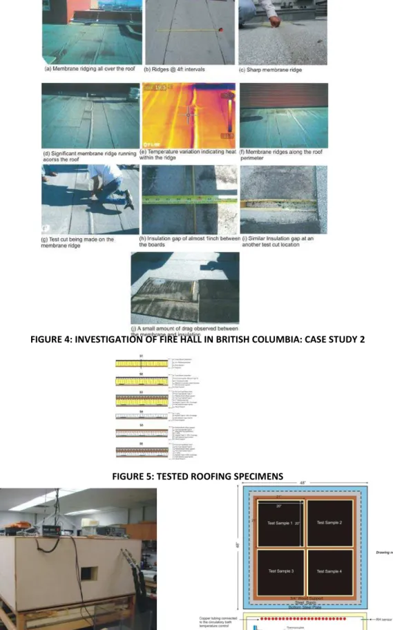
As shown in Figure 4a, significant membrane ridging occurred across the roof area. These ridges appeared to occur over insulation joints primarily, but due to being a mechanically attached system, the ridges extend beyond insulation joints in some areas. The membrane ridges were spaced at 4 ft intervals (Figure 4b).The thermographic image of the ridge area (Figure 4d) shows heated air within the ridges (Figure 4e). Different temperature variations can also be observed along the runs of insulation indicating uneven thermal value. At the roof perimeter as shown in Figure 4f, heat loss was observed both at the membrane ridges and at roof perimeter. When the membrane was cut at a large ridges as shown in Figure 4g , gaps were found in the in the polyisocyanurate insulation right below the ridge. The gaps between the boards were found to be ½ in. (12mm) and in some cases it was found be closer to 1 in. (25mm) as shown in Figure 4h and 4i. A small amount of drag was also observed on the exposed screw and fastener indicating the friction between the insulation shrinkage and membrane Figure 4j.
FIGURE 3: ROOF CONFIGURATION: CASE STUDY 2
FIGURE 4: INVESTIGATION OF FIRE HALL IN BRITISH COLUMBIA: CASE STUDY 2
Similar to the case study 1, the issue of membrane ridging or buckling also appeared in the case study 2. However, in case study 2, as shown in Figure xx, the system configuration was a mechanically attached modified bitumen system, where the membrane was attached to the structural deck only at its seam overlaps. In other word whatever the stresses are developed they are localized within the sheet as the edges of the sheet are fixed to the substrate. In this case, the plastic flow or the creep develops and relaxes within the sheet but it cannot propagate form one sheet to another. So in case study 2, the buckling phenomenon could not attributed to the membrane creep, but it could be said to be a membrane blister occurring at the insulation gaps. It should be noted that gaps around 1 inch were found in case study 2 between the insulation boards indicating that the insulation boards underwent a considerable dimensional change.
Usually blisters form in a hot-applied modified bituminous membrane for the same reason as in a BUR: voids built into the roof (Liu, 2000). Voids can result from skips in bitumen mopping, entrapped debris, uneven substrates, unrelaxed membranes, or entrapped gases resulting from moisture in the materials. During the heat of the day, air and moisture trapped in the void expand. The pressure developed in the void stretches the warm flexible membranes and displaces them to form a blister. During the night, the membranes cool, become stiff, and resist returning to their original shape. In the case study 2, as shown in Figure 2, the roof
Page 5 of 12
configuration comprised of vapor barrier and EPS below the Polyiso boards. The temperature cycle caused the insulation boards to shrink and form a gap or void between the boards. As the boards were not staggered during the layout, the insulation gap was in linear format across the roof. With the vapor barrier below the insulation, the trapped air in the insulation gap expands during the heat of the day inducing pressure on the membrane forming linear blister (crest shape) along the insulation gaps. Had there been no vapor barrier, the membrane would have troughed into the insulation gap like a simply supported beam.
Experimental Testing to Understand the Thermal Induced Stresses in Modified
Bitumen System
To understand the impact of the thermal induced stresses on the modified bitumen systems, a small scale experimental testing was conducted at the National Research Council of Canada in collaboration with Roofing Contractors Association of British Columbia ( RCABC) and Soprema Canada Inc. The main focus of this study was to determine the insulation shrinkage and component displacement in modified bitumen systems. Five roofing configurations as shown in Figure 5 were tested, S1: POLYISO Insulation - S2: POLYISO with Asphaltic Cover Board -S3: POLYISO with Particle cover board and Modified Bituminous membrane S4: EPS INSULATION -S5: EPS with Particle cover board -S6: EPS with Particle cover board and Modified bituminous membrane.While S1 and S4 are component evaluations, S3,S4, S5 and S6 are system evaluations.
FIGURE 5: TESTED ROOFING SPECIMENS
Experimental Apparatus
Figure 6 shows the test apparatus and the test specimen layout within the apparatus. The test Chamber, shown in Figure 6, is an insulated polycarbonate enclosure which is 48 in. (1220 mm) wide by 48 in. (1220 mm) long with a height of 20 in. (508 mm). The top chamber is fitted with a copper coil which is connected to a circulatory bath with a temperature range of -25˚C to 300˚C. The temperature is constantly monitored by thermocouples which are placed at different levels of the specimens and within the test chamber. For measuring the linear displacement of the roofing components, LVDT are installed between the parapet and the specimen. All the sensors are connected to a data acquisition system that records each sensor every hour.
FIGURE 6: TEST CHAMBER AND THE SPECIMEN LAYOUT WITHIN THE CHAMBER
Construction of Test Specimens
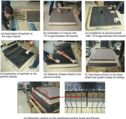
Five specimens with different components were tested and the method of construction varied depending on the insulation used. The deck used is ¾ in. (19 mm) Plywood set at an angle of 1˚ and remains constant for all the specimens (Figure 6). A self adhered vapor barrier was installed on the deck except each deck. The asphalt coverage was kept at approximately 20% which complies with what was observed at the school roof in Montreal (Case Study 1).The insulation was divided into four sections of 21 in. (533 mm). The cover board, when installed, was also divided into four sections of 20 in. (508 mm). Except S1, for the remaining five specimens, Type 2 asphalt was used as the adhering agent. The perimeter of the insulation, cover board and membrane was lined with a marker to identify any movement. Figure 7 shows the typical construction of S5.
Page 6 of 12
FIGURE 7: TYPICAL CONSTRUCTION OF S5
Test Methodology
All the samples were constructed at room temperature. With the exception of S1 and S2 all the remaining samples were subjected to testing cycles of 70o C to 5o C for 24 hours (12 hours at each temperature) for a total of 28 days as shown in Figure 8. Due to some internal problem with the circulatory bath, S1 and S2 were subjected to only 7 days of cycling of 70o C to 5o C for 12 hours each after the temperature was stabilized. The internal relative humidity was kept at 20 ± 5% for the hot cycle and 35% ± 5% for the cold cycle to avoid condensation on the specimens.
FIGURE 8: TEMPERATURE CYCLE OF THE TESTED SPECIMENS
Results and Discussion
Two parameters were monitored during this investigative study, one is dimensional change of the components (insulation and cover board) and the other is displacement of the roofing components – insulation, cover board and membrane from the parapet wall. During the construction stage, apart from the perimeter marking as shown in Figure 7g, the dimensions of all the individual components and the pre installed gap between the components were measured and recorded. At the end of every week of testing, the test was stopped and the change in dimensions, gap measurements and component displacement with the perimeter markings were recorded. After recording the data the test was resumed for the next round of temperature cycle. Based on the experimental observations , the results can be summarized as:
S1 and S2: S1 comprised of four polyisocyanurate boards cut to dimensions of 21 in. x 21 in
(533 mm x 533 mm) and mechanically fastened to the wood deck. As shown in Figure 9, the insulation boards underwent a maximum shrinkage of -1/16 in. (-1.7 mm) and -3/64 in. (-1 mm) in both X and Y respectively. There was no significant dimensional change of the asphaltic cover board nor there was any cover board displacement observed. With hot asphalt application, as shown in Figure 10, the shrinkage of the polyiso board was almost same as S1 and again there was no significant dimensional change of the cover board. However, in S2, the cover board underwent a pivoting movement of 3/32 in. (2.7 mm) from its original position.
FIGURE 9: MEASURED RESPONSE OF S1 FIGURE 10: MEASURED RESPONSE OF S2
S3: The layout of S3 is similar to S2 except in S3 a two ply modified bituminous membrane was
installed as the waterproofing membrane. Similar to S2, there was no significant dimensional changes observed on the ISO and particle board, however insulation and particle board movements were observed as discussed below in Figure11. One of the important observations on this system is the membrane movement on section 4. The composite ISO, particle board and the membrane moved from the parapet wall by 1/4 in. (6.5 mm) and as this composite section butted with the ISO on section 4, the particle boards also collided with each other. As the section 3 ISO and particle board could not move further due to the good bonding of the section 4, the displacement was transferred to the membrane on section 4, which displaced by almost 3/16 in. (5 mm).
FIGURE 11: MEASURED DIMENSIONAL CHANGE OF S3 FIGURE 12: MEASURED COMPONENT DISPLACEMENT OF S3
Page 7 of 12 S4: In S4 after 28 days of thermal conditioning, as shown in Figure 13, the maximum
dimensional changes observed were on section 4, which showed a maximum shrinkage of -1/8 in. (-3 mm) in both X and Y. This indicates that the maximum gap between two adjacent boards either in X or Y direction can be up to a maximum 1/4 in. (6 mm) and measured dimensional data verifies this rational
FIGURE 13: MEASURED DIMENSIONAL CHANGE OF S4
S5: S5 was similar to S4 except a two layer ship-lapped particle board with a thickness of 1/2 in.
(12 mm) each was installed on top of the EPS boards. The measured data from Figure 14 shows that both EPS and particle board underwent dimensional changes. A maximum shrinkage of -1/32 in. (-0.82 mm) in the X direction and -3/64 in. (-1.38 mm) in the Y-direction was observed on the EPS board section 1. In the case of the particle board, board 2 on section 2 underwent the maximum shrinkage of -1/32 in. (-0.82 mm) and -1/32 in. (-1.09 mm) in the X and Y directions respectively. Greater movement from the parapet was observed on section 3, where the composite EPS and the particle board moved by 1/8 in. (3.3 mm) (4.53-1.19).
FIGURE 11: MEASURED DIMENSIONAL CHANGE OF S5
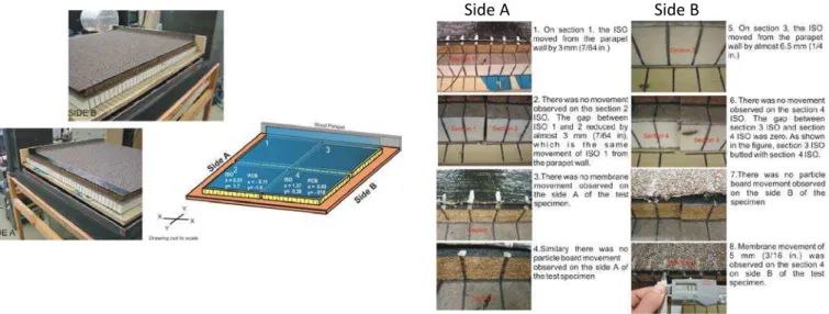
S6: In S6 a two ply modified bituminous membrane was installed as the waterproofing
membrane on the EPS and particle board making it a complete system. The base sheet was adhered to the particle board and the cap sheet was torched to the base sheet. Both the base and cap sheet were adhered to the parapet wall. On both sides of the system, Side A and B, marking lines were drawn on the membrane, particle board and insulation with reference to the lines drawn on the deck. Figure 15 shows the measured dimensional changes, which indicates that there was no significant dimensional changes observed on the EPS and particle board, however there was differential movement observed between insulation and particle board movements as discussed in Figure 16.
FIGURE 15: MEASURED DIMENSIONAL CHANGE OF S6 FIGURE 16: MEASURED COMPONENT DISPLACEMENT OF S6
Conclusions:
Two case studies were presented showing the problems of membrane ridging or membrane buckling in the field. Case study 1 identified that thermal stresses do occur in modified bitumen membrane and the plastic flow or creep within the membrane can cause ridging, especially in the fully adhered systems, if the membrane is poorly adhered or has least adherence to the substrate below. The component joints below the membrane are the weakest links for membrane adherence, and the case study 1 showed that how excessive asphalt at the joints lead to poor adherence and eventually lead to membrane ridging at most of the particle board joints. It is strongly recommended that the mop and flop hot asphalt application of EPS insulation should not be followed in the field as it can burn the insulation and eventually lead to roofing problems.
Case study 2 showed membrane buckling due to the impact of the insulation shrinkage or insulation gaps. Unlike case study 1, membrane attachment was mechanically fastened in case
Page 8 of 12
study 2. Even though the plastic flow or the creep would occur in this system, with time the stresses would have relax as there is no restraint offered by the substrate components as it being a mechanically fastened system. However, the membrane buckling still appeared on this roof due to the affect of insulation shrinkage. Insulation gaps as wide as 1 in. (25mm) were observed and as the system layout comprised of vapour barrier, there was trapped air in the insulation joints. With daily temperature variations, the pressure developed in the void might have stretched the warm flexible membrane displacing to form a blister along the insulation joint.
By simulating the air temperature without the solar radiation, the experimental study tested 6 different configurations of the modified bitumen systems both at the component and at system level to understand the thermal induced stresses on modified bitumen roofing systems. On the dimensional change, maximum gap between two adjacent insulation boards either in X or Y direction was found to be a maximum 1/4 in. Both the asphaltic and particle Cover board did not show any significant dimensional change, however the addition of particle cover board on top of the EPS insulation boards reduced the thermal strain of the EPS insulation by 54 % compared to just the EPS board. With the membrane installed, differential movements were observed between different sections of the system. The insulation boards either the EPS or the ISO were the primary translated components. Even though the present small scale experimental study could not simulate the membrane ridging or the creep of the membrane as observed in the field it does show the thermal strains of the roofing components and the differential movement between the components.
References
Baskaran, B. A.; Katsman, R.; Sexton, M.; Lei, W,(2003), “Investigation of Thermal Induced loads in Modified Bituminous Membrane” Construction and Building Materials, 17, 3, pp. 153-16.
Booth,R.J,(1997), ”Practical Experiences With Bituminous Low Slope Roofs in Cold Climates”, Proceedings of Fourth International Symposium on Roofing Technology, NRCA, pp 75-85, September 17-19, Gaithersburg, Maryland, USA.
Liu.K.K.Y, Paroli.R.M and Smith.T.L. (2000),”Blistering in SBS Modified Bituminous Roofs”, Construction Technology Update # 38, Institute for Research in Construction,
National Research Council of Canada, Ottawa K1A 0R6
Molleti, S., Beaulieu, P., Baskaran, B.A.,(2008), “Impact of Thermal Induced Stresses on Dimensional Stability of Roofing Assemblies”, Client Report, NRC Institute for Research in Construction, pp. 10, June 13, (B-1417.1)
Rossiter. W.J and M.E.Batts (1985), "Finite-Element Analysis of Temperature-Induced Stresses in Single-Ply Roofing Membranes", Durability of Building Materials, V. 2, pp. 195-208.
Solvason.K.R., and Handegord.G.O.(1976), “Ridging, Shrinking and Splitting of Built-Up Roofing Membrane”, Building Research Note, Division of Building Research, National Research Council Canada, Ottawa, Ont., Canada,K1A OR6
Turenne. R.G (1976), "Shrinkage of Bituminous Roofing Membranes", Canadian Building Digest #181, Division of Building Research, National Research Council Canada, Ottawa, Ont., Canada,K1A OR6.
Page 9 of 12
(a) Mechanically Attached System (b) Adhesive Applied System
FIGURE 1: TYPICAL LAYOUT OF MODIFIED BITUMEN ROOFING SYSTEM
FIGURE 2: INVESTIGATION OF SCHOOL ROOF IN MONTREAL: CASE STUDY 1
Page 10 of 12
FIGURE 4: INVESTIGATION OF FIRE HALL IN BRITISH COLUMBIA: CASE STUDY 2
FIGURE 5: TESTED ROOFING SPECIMENS
Page 11 of 12
FIGURE 7: TYPICAL CONSTRUCTION OF S5
FIGURE 8: TEMPERATURE CYCLE OF THE TESTED SPECIMENS
Page 12 of 12
FIGURE 11: MEASURED DIMENSIONAL CHANGE OF S3
FIGURE 12: MEASURED COMPONENT DISPLACEMENT OF S3
FIGURE 13: MEASURED DIMENSIONAL CHANGE OF S4 FIGURE 14: MEASURED DIMENSIONAL CHANGE OF S5
FIGURE 15: MEASURED DIMENSIONAL CHANGE OF S6 FIGURE 16: MEASURED COMPONENT DISPLACEMENT OF
S6
Side A Side B