Publisher’s version / Version de l'éditeur:
Advances in Powder Metallurgy & Particulate Materials-2011, 2, 9-Material Properties, 2011-01-01
READ THESE TERMS AND CONDITIONS CAREFULLY BEFORE USING THIS WEBSITE.
https://nrc-publications.canada.ca/eng/copyright
Vous avez des questions? Nous pouvons vous aider. Pour communiquer directement avec un auteur, consultez la
première page de la revue dans laquelle son article a été publié afin de trouver ses coordonnées. Si vous n’arrivez pas à les repérer, communiquez avec nous à PublicationsArchive-ArchivesPublications@nrc-cnrc.gc.ca.
Questions? Contact the NRC Publications Archive team at
PublicationsArchive-ArchivesPublications@nrc-cnrc.gc.ca. If you wish to email the authors directly, please see the first page of the publication for their contact information.
NRC Publications Archive
Archives des publications du CNRC
This publication could be one of several versions: author’s original, accepted manuscript or the publisher’s version. / La version de cette publication peut être l’une des suivantes : la version prépublication de l’auteur, la version acceptée du manuscrit ou la version de l’éditeur.
Access and use of this website and the material on it are subject to the Terms and Conditions set forth at
Copper strengthening of PM steel parts
Bernier, Fabrice; Gauthier, Maxime; Plamondon, Philippe; L’Espérance,
Gilles
https://publications-cnrc.canada.ca/fra/droits
L’accès à ce site Web et l’utilisation de son contenu sont assujettis aux conditions présentées dans le site LISEZ CES CONDITIONS ATTENTIVEMENT AVANT D’UTILISER CE SITE WEB.
NRC Publications Record / Notice d'Archives des publications de CNRC:
https://nrc-publications.canada.ca/eng/view/object/?id=58f25e4e-d4da-465a-b6a3-182c87b9a091 https://publications-cnrc.canada.ca/fra/voir/objet/?id=58f25e4e-d4da-465a-b6a3-182c87b9a091
Copper strengthening of PM steel parts
Fabrice Bernier and Maxime Gauthier
Powder Forming Group, Industrial Materials Institute of the National Research Council Canada, 75 De Mortagne blvd., J4B 6YA Boucherville, Canada
Philippe Plamondon and Gilles L’Espérance
Materials Engineering Program, École Polytechnique de Montréal, 2900 Édouard-Montpetit blvd., H3T 1J4 Montréal, Canada
Abstract
Copper is often used in steel powder metallurgy due to its significant strengthening effect. The large difference in solubility of copper in austenite at sintering temperatures and in ferrite at room temperature can lead to precipitation hardening. Work was carried out to gain a better understanding of the
strengthening mechanisms associated with copper. Microhardness measurements combined with X-ray energy dispersive spectrometry (EDS) in a scanning electron microscope were used to quantify the strengthening effect of copper in pearlite and in martensite. Transmission electron microscopy was used to observe nanometer-sized copper precipitates. The detailed characterization of the microstructure and properties contribute to a better understanding and use of copper in sintered steel parts.
1.
Introduction
Copper, after carbon is the most widely used alloying element in ferrous powder metallurgy.1 It is also the
infiltrant of choice in PM infiltrated steel due to the small contact angle between liquid copper and steels
and the absence of a reaction between steel and copper.2-4 Indeed, the Fe-C-Cu phase diagram shows no
intermediate phase between Fe-C and copper. This phase diagram can be summarized by a maximum solubility of copper between 8-10 wt.% in the austenitic phase at 1120°C and a near-zero maximum
solubility of copper at ambient temperature.5 This large difference of solubility of copper with
temperature offers the possibility of using precipitation hardening (or age hardening) to strengthen copper containing steels.
It is interesting to compare the strengthening mechanism from precipitation hardening with that obtained by martensite quenching and tempering. The first step of precipitation hardening, solution heat treatment, consists of heating the alloy to a temperature range where the solute is dissolved so that a single phase structure is obtained. On the other hand, during the first step of martensite hardening, (i.e austenitization) the steel is heated to around 900°C. i.e. in single phase austenitic region. The second step of both heat treatments is a rapid cooling, also called quenching. For martensitic steels, the allotropic transformation (diffusionless) of austenite to martensite hardens the alloys. In contrast, precipitation hardening does not
occur during the quenching step. This step is used to obtain a supersaturated solid solution (single phase). Hardening occurs during precipitation (or ageing), which is achieved by reheating the alloys at a set temperature below the solvus for a suitable time. Solute concentration, temperature and time will affect
the size and distribution of the precipitates.6 The temperature should be high enough to allow precipitation
to occur in a reasonable amount of time whilst being low enough to avoid coarsening of the precipitates and redissolving the solute. A reheating treatment is also carried out after quenching of the martensitic steel. This step, called tempering, is used to reduce the martensite hardness and regain some ductility and toughness. Finally, even if martensitic and precipitation hardened steels are not hardened by the same mechanism, their processing steps are similar, thus offering the possibility to use both hardening mechanisms simultaneously on the same steel parts.
High strength low alloy steels (HSLA) were developed for applications requiring high strength and toughness by refining grain size and using both strengthening mechanisms. These very low carbon steels (< 0.06%C) contains different alloying elements, such as chromium, niobium, vanadium and
molybdenum.7-9 Some of these wrought steels also use copper to obtain precipitation hardening and
increase weldability. Many recent articles focus on the effect of copper in HSLA wrought steels.10-13
Some show the effect of temperature and time on the evolution of copper precipitates and their impact on
the mechanical properties.10,13 Urstev et al. (2008) clearly illustrate the interdependence of
time/temperature/copper content on the microhardness of such steels. However, Isheim et al. (2006), Fine et al. (2007) and Mishra et al. (2002) show the difficulty to clearly describe the precipitation behavior of copper primarly due to the nanometric size of the precipitates and their complex composition (several alloying elements are present).
The precipitation behavior of copper and its impact on the mechanical properties of various PM steels are studied in this paper. Two PM steel families are studied: copper-infiltrated steel and a low alloy steel. Micro- and nano hardness measurements have been used in combination with high spatial resolution microanalysis in a scanning electron microscope to clarify the relationship between heat treatment, microstructure and mechanical properties. Transmission electron microscopy (TEM) was also used to characterize the nanometer scale copper precipitates.
2.
Experimental
Two PM steels are used in this study; one is a copper infiltrated steel corresponding to a FX1008 based on the MPIF35 designation. The other is a low alloy copper PM steel, with the following compositions: Fe-3Cu-1.5Mo-0.05C where molybdenum is prealloyed and copper and graphite are admixed. That
composition can be associated to a FC-0200 based on the MPIF35 designation. The two alloys were studied in a different metallurgical state depending on the heat treatment, as described in Table 1. In the table, following the alloy type, the terms AS and AQ stand for as-sintered and as-quenched respectively and the number stands for the tempering or ageing temperature used. All alloys where first sintered at
1120°C for 30 minutes in a 90% N2 – 10% H2 reducing atmosphere, the FX1008 alloy being infiltrated
during the sintering step. Most samples were then heated to 900°C for an hour in a nitrogen atmosphere for austenitization/solution heat treatment before they were water quenched. Finally, each alloy was tempered/aged for an hour at three different temperatures.
Most of the microstructural characterization and microhardness/nano hardness measurements were done on as-polished transverse rupture strength specimens in the unetched condition. Microstructural analysis was carried out on a high resolution field emission gun scanning electron microscope (JEOL 7600F FEG) equipped with a low-angle backscattered detector (LABE). A transmission electron microscope (JEOL 2100F) was also used. Microhardness measurements were done with a load of either 50 or 25gf (500 or 250 mN) and nanohardness measurements were carried out on a MTS nano G200 nanoindenter using a Berkovich tip with a maximum load of 1.5 gf (15mN). The Oliver and Pharr method was used to
determine the nanohardness and elastic modulus from the load to depth of indentation curves.14
Table 1. Materials and processes
Designation Composition Sintering temperature (°C) Austenitization /Solution heat treatment (°C) Quenching Tempering/ Ageing (°C) FX1008-AS Fe-8Cu-0.7C 1120 - - -
FX1008-AQ Fe-8Cu-0.7C 1120 900/60/N2 Water -
FX1008-300 Fe-8Cu-0.7C 1120 900/60/N2 Water 300
FX1008-500 Fe-8Cu-0.7C 1120 900/60/N2 Water 500
FX1008-700 Fe-8Cu-0.7C 1120 900/60/N2 Water 700
FC0200-AQ Fe-3Cu-1.5Mo-0.05C 1120 900/60/N2 Water -
FC0200-300 Fe-3Cu-1.5Mo-0.05C 1120 900/60/N2 Water 300
FC0200-500 Fe-3Cu-1.5Mo-0.05C 1120 900/60/N2 Water 500
FC0200-700 Fe-3Cu-1.5Mo-0.05C 1120 900/60/N2 Water 700
3.
Results and discussion
3.1 Copper infiltrated steel: as-sintered
The first step of this study was to evaluate the strengthening effect of copper after the cooling step of a standard sintering process. A copper infiltrated part was used since it enables to study the effect of copper content on the microhardness of pearlite. Figure 1 shows the microstructure of the FX1008 alloys in the as sintered condition. An EDS linescan is also included to illustrate the variation in the copper content.
Fig. 1 FX1008-AS specimens observed by SEM with an EDS copper linescan
Two regions are distinguishable, a copper infiltrated regions and the steel matrix, which is pearlitic. MnS inclusions are also observed in the pearlitic matrix: they are present as machinability aids. The linescan also shows that the steel matrix is copper-rich within a band of at least 5 μm near the copper infiltrated regions. Table 2 presents the microhardness measurements made on two regions in the steel matrix: the first region is within 5 μm of a copper infiltrated region, the second one is also in the pearlitic region but at least 20 μm away from any copper infiltrated regions. Also included in Table 2 is the semi-quantitative copper content at 2, 5 and 20 μm from the copper infiltrated regions.
Table 2. Effect of copper content on the microhardness of pearlitic steel in the FX1008-AS specimens
Distance from copper infiltrated
regions (μm) Microhardness (HV0.025)
Semi-quantitative copper content (%)
2
265±9.0 5.2
5 3.0 20 227±10.0 1.1
An increase in microhardness of more than 15% is observed in pearlite and is associated with a higher copper content. This can be explained by the presence of copper precipitates in the pearlitic matrix. However as seen in figure 1, copper precipitates were not observed with standard scanning electron microscopies. On the other hand, when using a high resolution scanning microscope we can observe that the high local copper concentrations leads to copper precipitation during cooling as seen in fig.2. Hence the use of a field emission gun scanning electron microscopy (FEG-SEM) combined with a low angle backscattered electron (LABE) detector offers the possibility to observe precipitates that are smaller than 50 nm. An impressive advantage of such a combination of techniques is the high contrast obtained for two elements with a similar atomic number: iron with a Z of 26 and copper with a Z of 29. Finally, figure 2 shows that precipitates are present in the pearlitic matrix within a 5 μm band of the copper infiltrated region.
Fig 2. Copper precipitates in the FX1008-AS specimen observed by SEM with a LABE detector a) low magnification b) high magnification
To further appreciate the size and shape of the precipitates, TEM observations were carried out (Figure 3). The spherical copper precipitates are uniformly distributed, in comparison to the lamellar morphology of pearlite. Finally, observations in the SEM were done using the TEM samples and a specially designed scanning transmission electron microscopy (STEM) detector (Figure 4), which confirm that the copper precipitates are less than 50 nm, and most of them are even under 30 nm. Figure 4 clearly shows that very fine precipitates (< 5 nm) are present and can be resolved using this microscopy technique.
Fig. 3 Copper precipitates in the FX1008-AS specimen observed by TEM
Fig. 4 Copper precipitates in the FX1008-AS specimen observed in the SEM using a TEM
sample and a scanning TEM detector Nanohardness measurements were also made to measure the strengthening effect of these precipitates with a higher spatial resolution than microhardness. Indeed, when microhardness was evaluated with a load of 25gf (HV0.025), the size of the indentation (diagonal) is more than 10 μm but when
nanoindentation was carried out with a load of 1.5 gf the indentation size is less than 3 μm, as seen in figure 5. Five indentations were made within the 5 μm from the copper regions (fig 5.a-c) and hardness and elastic modulus yield values, of 4.2 ± 0.3 GPa and 221 ± 10 GPa were obtained, respectively.
However, when five other indentations were made away from the copper rich region (fig. 5d) the hardness fell to 3.4 ± 0.5 GPa and the elastic modulus remained similar at 218 ± 15 GPa. It is thus clearly shown that copper precipitates are responsible for a 23% increase in hardness. Finally, it should be noted that the nanohardness values are consistent to those found in the literature for different steels starting at around 2
GPa for ferrite and reaching around 6 GPa for martensite.15-17
Fig. 5 Nanohardness indentations observed in SEM a) Overview b) and c) higher magnification in the copper-rich region and d) high magnification in the lower copper content region
3.2 Copper infiltrated steel: quenched and tempered
To achieve a more homogeneous distribution of copper into the steel matrix, a solution treatment was done at 900°C for an hour. This treatment also serves as an austenitizing treatment. Hence, after water quenching, an austenite to martensite transformation occurs. Also, even if the solubility of copper in steel is close to 0% at room temperature, the high cooling rate should impede the diffusion of copper so that it remains in supersaturated solid solution within the martensitic matrix. However, as seen in figure 6, some copper precipitates were observed in the FX1008-AQ samples. These precipitates were smaller and less numerous than those observed in the as-sintered sample. The presence of these precipitates can be explained by the inability to completely dissolve the precipitates during the solution heat treatment. Indeed, the ternary alloy phase diagram shows that the maximum solubility of copper in austenite during
sintering is near 7.5% (7.4% at 1050°C) whilst it is about 5.5% at 900°C (5.5% at 925°C).5
Fig. 6 FX1008-AQ specimen observed by SEM
To precipitate the excess copper, ageing treatments at different temperatures were carried out. The size and spatial distribution of the Cu precipitates were similar after ageing at 300° C and 500° C (compare fig. 7a) and 7b) with figures 7c) and 7d)). However, when the ageing temperature is increased to 700°C, an important increase in size of the precipitates is clearly visible (fig. 7 e) and f)). The ageing treatment also acts as a tempering treatment for the martensite: the lower magnification images (fig. 7 a), c) and e))
show the evolution of martensite with increasing tempering temperature. Coarsening of martensite is clearly visible.
FX1008-QT300
FX1008-QT500
FX1008-QT700
Fig. 7 FX1008-QT specimens observed by SEM after ageing at a) and b) 300°C; c) and d) 500°C and e) and f) 700°C
The effect of the ageing/tempering treatment on the microhardness of the copper-containing martensite is shown in figure 8 and is compared to data found in the literature for the effect of the tempering
temperature on the hardness of martensite (for a Fe-0.7C alloy).18 These results show that softening of
martensite dominates the effect of Cu precipitates. Indeed, the hardness of the martensite is not affected by the presence of copper precipitates, as it follows the same values than copper free steel with the same carbon content. These results on the predominance of martensite softening compared to copper hardening
was also reported by Schade et al. in 2010.19
100 200 300 400 500 600 700 800 900 1000 0 100 200 300 400 500 600 700 800 Mic roha rd n e ss (H V 0 .0 5 ) Tempering temperature (Celsius) FX1008 Fe‐0.7C [Grange et al. 1977]
Fig. 8 Effect of the tempering temperature on the microhardness of FX1008 quenched samples. The
microhardness of a Fe-0.7 C alloy is also shown18
3.3 Low alloy copper steel
Figure 9 shows the effect of the ageing temperature on the microhardness of the quenched FC0200 PM alloy. These results are compared to the microhardness of tempered martensite of a Fe-0.05C alloy. Hardness of the low alloy steel aged at 300°C decreases by about 20 HV when compared to the as-quenched condition. When the ageing temperature is increased from 300°C to 500°C, an increase in hardness of 40 HV is observed. For that ageing condition, the hardness is even higher than that of the as-quenched conditions and, most interestingly, equal to the high carbon FX1008-500 alloy (see fig. 9). When compared to the data from the literature, the effect of copper on the hardness is even more impressive, the hardness of the martensite for the FC0200 alloy being more than 200 HV higher the expected hardness of copper-free steel with the same carbon content. A steep decrease (≥ 125 HV) in hardness is observed when the FC0200 alloy is aged at 700°C. The effect of tempering temperature on the TRS values follows the same trends than the microhardness results. The alloys were pressed at 50 TSI to
a density of 7.1 g/cm3. The highest values, 1250 MPa, is obtained for the alloys aged at 500°C and this
value is higher than the 1030 MPa tranverse rupture strength reported in the MPIF standard 35 for a FC0208-95HT.
100 150 200 250 300 350 400 450 0 100 200 300 400 500 600 700 800 Micr o h ar dn e ss (H V0.05) Tempering temperature (Celsius) FC0200 Fe‐0.05C [Grange et al. 1977] 600 700 800 900 1000 1100 1200 1300 1400 0 100 200 300 400 500 600 700 800 TR S (M P a ) Tempering temperature (Celsius)
Fig. 9 Effect of tempering temperature on the microhardness (a) and on TRS (b) of FC0200 quenched
samples. The microhardness of a Fe-0.05 C alloy is also shown18
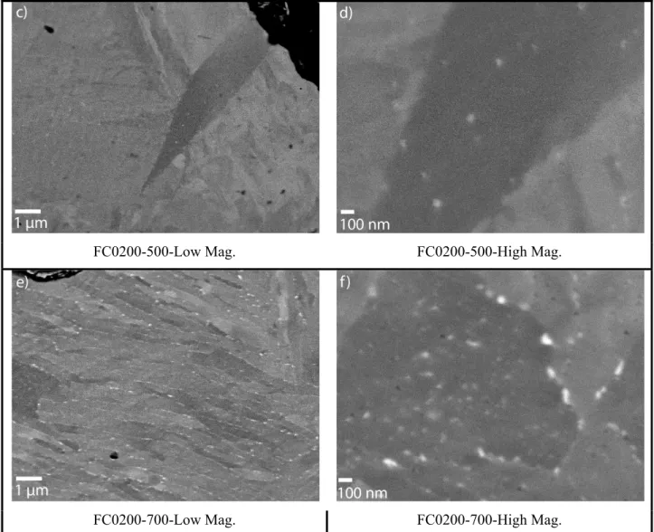
To understand these mechanical properties results, FEG-SEM observations were carried out. Figure 10 summarizes the different observations. Figure 10a) and 10b) show that in the as-quenched condition and after an ageing treatment at 300°C copper precipitates were not observed. After the ageing treatment at 500°C, some precipitates could be seen (fig 10c) and d)). In order to explain the maximum mechanical properties obtained at 500°C, smaller precipitates that cannot be observed by high resolution SEM are most probably present. TEM observations should be carried out to confirm their presence and size.
Finally, after the ageing treatment at 700°C (fig 10e) and f)), many uniformly distributed larger (≥ 50 nm)
precipitates are observed. Since the mechanical properties decrease for the FC0200-700 alloys, it can be concluded that the size of the precipitates should be under 50 nm to achieve maximum properties.
FC0200-500-Low Mag. FC0200-500-High Mag.
FC0200-700-Low Mag. FC0200-700-High Mag.
Fig. 10 FC0200 specimens observed by SEM after a) quenching and ageing treatment: b) at 300°C; c) and d) at 500°C; e) and f) at 700°C
4.
Conclusions
In this study, the copper strengthening mechanisms for two alloys were studied using microstructural characterization and hardness measurements. The following conclusions can be made for the:
• FX1008 in the as-sintered condition:
- Copper precipitation increases the hardness up to 23% of the steel matrix within a 5 μm
band of the Cu-infiltrated areas.
• FX1008 in the quenched and tempered condition:
- Precipitation hardening by copper precipitates is completely masked by softening of the
martensite
• FC0200 in the quenched and aged condition:
- Copper precipitation increases the hardness and TRS when aged at 500°C
Also, more general conclusions can be made with regards to the methods used in this study to characterize the microstructure and the mechanical properties of these alloys:
• Scanning electron microscopy with a field emission gun (FEG) and a low angle backscattered electron (LABE) detector can be used to observe nanometric precipitates in a bulk steel sample. Such observations could only have been done in TEM. Numerous other applications can be envisaged for these methods which are considerably faster and easier than TEM.
• Nanoindentation can be used to measure with high spatial resolution the effect of a chemical
gradient
5.
Acknowledments
The authors would like to acknowledge Daniel Simard from IMI-CNRC for metallographic preparation and Philippe Beaulieu from École Polytechnique for semi-quantitative EDS analysis.
6.
References
1. U. Engström, ‘Copper in P/M steels’, Int. J. Powder Metall., 2003, vol. 39, no. 4, pp.51-60.
2. R. M. German, Sintering theory and practice, 1996, John Wiley & Sons. Inc, New York, NY.
3. R. Lumpkins, Jr., ‘Theoretical review of the copper infiltration of PM components’. Powder
Metall. Int., 1985, vol.17, no. 3, pp.120-123.
4. P. Lowhaphandu & J.J. Lewandowski, ‘Fatigue and fracture of porous steels and Cu-infiltrated
porous steels’, Metall. Mater. Trans. A., 1999, vol. 30, no. 2, pp.325-334.
5. in ‘ASM metal handbook’, Vol. 3, ‘Alloy Phase Diagrams’, 1999, Materials Park, OH, ASM
International. p. 3.27.
6. in ‘ASM metal handbook’, Vol. 4, ‘Heat Treating’, 1999, Materials Park, OH, ASM
International. pp. 841-843.
7. S.K. Mishra, S. Das and S. Ranganathan, ‘Precipitation in high strength low alloy (HSLA) steel:
A TEM study’, Mater. Sci. Eng. A, 2002, vol. 323, no.1-2, pp. 285-292.
8. S. Sivaprasad, S. Tarafder, V.R. Ranganath, and K.K. Ray, ‘Effect of prestrain on fracture
toughness of HSLA steels’, Mater. Sci. Eng. A, 2000, vol. 284, no. 1-2, pp.195-201.
9. S.K. Dhua, A. Ray and D.S. Sarma, ‘Influence of tempering on the microstructure and
mechanical properties of HSLA-100 steel plates’, Metall. Mater. Trans. A., 2001, vol. 32, no. 9, pp.2259-2270.
10. A. Ghosh, S. Das and S. Chatterjee, ‘ Ageing behavior of a Cu-bearing ultrahigh strength steel’,
Mater. Sci. Eng. A, 2008, vol. 486, no. 1-2, pp.152-157.
11. M.E. Fine, J. Z. Liu and M.D. Asta, ‘An unsolved mystery: the composition of bcc Cu alloy
precipitates in bcc Fe and steels’, Mater. Sci. Eng. A, 2007, vol. 463, no. 1-2, pp. 271-274.
12. D. Isheim, R. P. Kolli, M. E. Fine and D.N. Seldman, ‘An atom-probe tomographic study of the
temporal evolution of the nanostructure of Fe-Cu based high-strength low-carbon steels’ Scripta
Materialia, 2006, vol. 55, special issue 1, pp.35-40.
13. V.N. Urtsev, D.A. Mirzaev, I. L. Yakovleva and N. I. Vinogradova, ‘Transformation of austenite
in Fe-Cu alloys. III: Copper precipitation during cooling and holding of steels alloyed with copper’, Physics of Metals and Metallography, 2008, vol 105, no. 5, pp. 477-483.
14. W.C. Oliver, G.M. Pharr, ‘Improved technique for determining hardness and elastic modulus
using load and displacement sensing indentation experiments’ Journals of Materials Research, 1992, vol. 7, no. 6, pp. 1564-1580.
15. M. Delincé, P.J. Jacques and T. Pardoen, ‘Separation of size-dependent strengthening
contributions in fine-grained Dual Phase steels by nanoindentation’, Acta Materiala, 2006, vol. 54, no. 12, pp. 3395-3404.
16. J. Moon, K. Sanghoon, J. Jang, J. Lee and C. Lee, ‘Orowan strengthening effect on the
nanoindentation hardness of the ferrite matrix in microalloyed steels’, Mater. Sci. Eng. A, 2008, vol. 487, no. 1-2, pp. 552-557.
17. M.-L. Zhu, F.-Z. Xuan, ‘Correlation between microstructure, hardness and strength in HAZ of
dissimilar welds of rotor steels’, Mater. Sci. Eng. A, 2010, vol. 527, no. 16-17, pp. 4035-4042.
18. R. A. Grange, C. R. Hribal and L.F. Porter, ‘Hardness of tempered martensite in carbon and low
alloy steels’, Metall. Trans. A., 1977, vol. 8A, pp.1775-1785.
19. C. Schade, T. Murphy, A. Lawley and R. Doherty, ‘Processing and properties of a dual phase PM
steel’ Advances in Powder Metallurgy & Particulate Materials, Metal Powder Industries Federation. 2010.