Publisher’s version / Version de l'éditeur:
Proceedings of COM 2015, 2015
READ THESE TERMS AND CONDITIONS CAREFULLY BEFORE USING THIS WEBSITE. https://nrc-publications.canada.ca/eng/copyright
Vous avez des questions? Nous pouvons vous aider. Pour communiquer directement avec un auteur, consultez la première page de la revue dans laquelle son article a été publié afin de trouver ses coordonnées. Si vous n’arrivez pas à les repérer, communiquez avec nous à PublicationsArchive-ArchivesPublications@nrc-cnrc.gc.ca.
Questions? Contact the NRC Publications Archive team at
PublicationsArchive-ArchivesPublications@nrc-cnrc.gc.ca. If you wish to email the authors directly, please see the first page of the publication for their contact information.
This publication could be one of several versions: author’s original, accepted manuscript or the publisher’s version. / La version de cette publication peut être l’une des suivantes : la version prépublication de l’auteur, la version acceptée du manuscrit ou la version de l’éditeur.
Access and use of this website and the material on it are subject to the Terms and Conditions set forth at
Hybrid laser-arc welding of cast martensitic stainless steel ca6nm:
post-weld tempered microstructure and mechanical properties
Mirakhorli, F.; Cao, X.; Pham, X-T.; Wanjara, P.; Fihey, J.L.
https://publications-cnrc.canada.ca/fra/droits
L’accès à ce site Web et l’utilisation de son contenu sont assujettis aux conditions présentées dans le site LISEZ CES CONDITIONS ATTENTIVEMENT AVANT D’UTILISER CE SITE WEB.
NRC Publications Record / Notice d'Archives des publications de CNRC:
https://nrc-publications.canada.ca/eng/view/object/?id=38509221-a78d-4ea5-bd1a-e3f818d4034a https://publications-cnrc.canada.ca/fra/voir/objet/?id=38509221-a78d-4ea5-bd1a-e3f818d4034aHYBRID LASER-ARC WELDING OF CAST MARTENSITIC STAINLESS STEEL CA6NM: POST-WELD TEMPERED MICROSTRUCTURE AND MECHANICAL PROPERTIES
*F. Mirakhorli1,2, X. Cao2, X-T. Pham1, P. Wanjara2 and J. L. Fihey1
1École de technologie supérieure, Montréal, Québec, Canada, H3C 1K3 2National Research Council Canada – Aerospace, Montréal, Québec, Canada, H3T 2B2
(*Corresponding author: Fatemeh.mirakhorli.1@ens.etsmtl.ca)
ABSTRACT
Single-pass hybrid laser-arc welding of 10-mm thick cast plates of CA6NM, a low carbon martensitic stainless steel, was carried out in butt joint configuration using a continuous wave fiber laser at its maximum power of 5.2 kW over welding speeds ranging from 0.75 m/min to 1.2 m/min. The microstructures from the fusion zone to the heat affected zone and base metal were characterized after post-weld tempering at 600°C for 1 hour. From optical and scanning electron microscopy examination, the fusion zone was observed to mainly consist of tempered lath martensite and some residual delta-ferrite. The mechanical properties including microindentation hardness, ultimate tensile strength and Charpy impact energy were evaluated in the post-weld tempered condition and correlated to the microstructures and defects. The ultimate tensile strength and Charpy impact energy values of all the fully penetrated welds in the tempered condition were acceptable according to ASTM, ASME and industrial specifications. The failure mechanisms during tensile deformation and Charpy impact loading were examined by scanning electron microscopy, fractography and optical metallographic analysis near the fracture origin.
KEYWORDS
Hybrid laser-arc welding (HLAW); Cast stainless steel; Post-weld heat treatment; Microstructure; Mechanical properties.
NOMENCLATURE
Ac1 Temperature at which austenite begins to form during heating
BM Base metal
EBW Electron beam welding FCAW Flux core arc welding
FZ Fusion zone
GMAW Gas metal arc welding GTAW Gas tungsten arc welding
HAZ Heat-affected zone
HLAW Hybrid laser-arc welding Mf Martensite finish temperature
Ms Martensite start temperature
OM Optical microscopy PMZ Partially melted zone PWHT Post-weld heat treatment SEM Scanning electron microscopy
INTRODUCTION
Hydropower is one of the most widely used renewable sources of energy for electricity generation. Considering the long-service life of hydropower systems that can operate for more than five decades, proper design and manufacturing are critical for achieving high performance with low operational and maintenance costs. The most important part of any hydraulic power system is the turbine that is an assembly of various sub-components, e.g., runner blades, crowns and bands. These components are fabricated commonly from thick-walled stainless steel alloys, such as CA6NM, which is a low carbon martensitic stainless steel that is manufactured in cast form and has high strength, good toughness and corrosion resistance (Bilmes, Solari, & Llorente, 2001). However, the assembly and joining of the large hydroelectric turbine components is a great challenge from the perspective of the highly complex blade geometry and sizeable overall dimensions. Thus, the manufacturing quality and cost of the turbine are highly dependent on the ability to join such low carbon cast martensitic stainless steel components using methods that can provide high productivity, low material consumption and good joint integrity with any imperfections and distortion remaining within acceptable levels. To date, due to the relatively low investment costs of manual and semi-automatic arc welding systems, such as GTAW, GMAW and FCAW, arc welding with filler material has been widely used in industry to assemble the turbine. However, joints welded using arc-based manual welding processes exhibit a relatively large HAZ, high residual stresses, and distortion due to the considerable heat input and large thermal gradients from the multiple passes required for assembly. Also, compared to more advanced processes, the operational cost for assembly is high for arc-welding due to its relatively slow speed (low production rate), high labor intensity and cost of skilled welders, and considerable consumable costs; this latter is related to the small penetration depth that requires extensive grooving of the thick joint seam followed by multiple welds with filler metal addition under shielding gas protection. In the present context, where the capital expenditure for advanced manufacturing systems has decreased considerably, the high operating expenditure of arc welding processes may override their manufacturing sustainability. Hence investment in the development and introduction of alternative advanced welding and/or repair technologies that can improve the weld quality and performance, whilst reducing the overall fabrication costs is necessary for turbine manufacturers to be sustainable and cost-efficient in a global market.
For hydroelectric turbine assembly, the HLAW process is believed to offer a highly competitive solution to improve the overall performance by combining the high energy density and fast welding speed of the laser technology for deep penetration at a high production rate with the good gap bridging and feeding ability of an arc process (Mahrle & Beyer, 2006). Hence the synergistic interactions of the laser and arc heating sources in HLAW enable full penetration in thick gage sections using a single pass or fewer passes – depending on the laser power – that, in turn, reduce the heat input, size of the FZ and HAZ, thermal cycling, residual stresses and distortion in the assembly, relative to conventional arc welding alone.
In the present work, a single-pass HLAW process was developed to join 10-mm thick CA6NM martensitic stainless steel plates at three different welding speeds, namely 0.75, 1.0 and 1.2 m/min. Post-weld tempering at 600°C for 1 hour was applied according to the recommended guidelines in ASME sec. IX for welding and brazing qualifications of boiler & pressure vessel. The microstructure of the welds in the tempered condition was characterised using OM and SEM. The mechanical performance of the tempered welds was evaluated through measurement of the microindentation hardness, ultimate tensile strength and Charpy impact energy, which were then correlated to the microstructural evolution. Fractography on the fracture surface of the tensile and Charpy impact specimens was performed to identify the failure origins and mechanisms.
EXPERIMENTAL
Cast ASTM A743 grade CA6NM was received in plate form with a chemical composition as listed in Table 1. The 10-mm thick as-received plates were extracted from a newly cast CA6NM turbine runner blade and were heat treated as follows: (1) normalizing by first heating at a rate of 60°C/hr to 800°C and holding for 8 hrs followed by heating at a rate of 25°C/hr to 1030°C and holding for 27 hrs, (2) air cooling to a temperature below the martensite finish temperature (Mf≈ 90°C), and (3) tempering by heating
at a rate of 36°C/hr to 640°C and holding for 27 hrs followed by cooling at a rate of 25°C/hr. The CA6NM plates were then machined into coupons of 150 mm × 75 mm × 10 mm for the HLAW trials.
The laser equipment consisted of an IPG photonics 5.2 kW continuous wave solid-state Yb-fiber laser attached to an ABB robotic mounting arm. A collimating lens of 200 mm, a focal lens of 300 mm and a fiber diameter of 0.20 mm were employed to produce a nominal focusing spot diameter of 0.30 mm. The defocusing distance was 2.5 mm under the workpiece top surface and the laser head was inclined 5° from the vertical position during welding. A Fronius Trans Pulse Synergic 4000 CMT (Cold Metal Transfer) GMAW power supply was used in tandem with this laser system. The top surface of the workpiece was shielded using a mixture of 96% argon and 4% oxygen at a flow rate of 23.6 l/min that was fed through a GMAW nozzle, while the bottom surface was shielded using 100% argon at a flow rate of 9.5 l/min.
A single-pass HLAW process was developed to obtain full penetration in 10-mm thick CA6NM plates with a Y-groove butt joint having a bevel angle of 30º. The root size was 5 mm with a gap size of about 0.2 mm. The chemical composition of the AWS ER410NiMo filler wire (φ 1.14 mm) that was used is given in Table 1. As indicated in Table 2, HLAW was conducted at different welding speeds and the highest accessible laser power in “laser leading” mode. In accordance with recommended guidelines, post-weld tempering was performed on the post-welded assemblies according to ASME Section IX at a holding temperature of 600°C for 1 hr at heating and cooling rates of 50°C/hr.
Table 1 Chemical composition of cast CA6NM stainless steel and ER410NiMo filler metal
Elements C Si Mn P S Cr Ni Mo Cu Others
CA6NM 0.041 0.454 0.756 0.032 0.008 13.28 4.31 0.520 0.071 0.11 410NiMo 0.02 0.37 0.34 0.017 0.0009 12.18 4.57 0.42 0.12
-metall reinfor specim polish solutio + 80 m by ele welds electro indent 0.15 m respec mm an arc we condu 55 mm (Figur SATE SEM. tests. Figu Macro speed precip keyho the fu equilib Sam # 1 2 3 After HLAW lographic, tran rcement at the mens extracted hed using 3 an on to observe t ml H2O) to rev ectro-etching in was examined on microscope tation machine mm between ea Tensile and ctively. The fla
nd a thickness elds could be ucted at room te m × 9 mm × re 1b).The Cha EC SI-1C3 syst In addition, th ure 1 Specimen ostructure Figure 2a s of 1.0 m/min. pitation of disso les (Mirakhorl usion boundary brium ternary mple # Laser p (kW 1 5.2 2 5.2 3 5.2 Table 2 E
W, the top and sverse tensile e root, which r from each wel nd 1 μm diamo the general ma veal the marten n a 20% aque d using an inve e. Microhardne e (Struers Dura ach indentation d Charpy imp at rectangular t of 9 mm (Figu located within emperature usi 10 mm with a arpy impact te tem. The fractu
he microstruct (a) n geometries fo sha shows a typica Some porosity olved gas at so li, Cao, Pham, y after post-we phase diagra ower W) Weldi (m 2 0 2 2 FZ +HAZ Experimental de d bottom surfac and Charpy im reduced the joi
ld were ground ond suspension acrostructure or nsite and delta-eous solution o erted optical m
ess profiles ac amin A300) at n.
pact tests were transverse tens
ure 1a). It is n n the 20 mm g ing a 300 kN T a 2-mm deep ests were cond
ure surfaces of ture near the f
or (a) transvers aded region) an RESULTS al transverse s y was observe olid/liquid inte Wanjara, & Fi eld tempering am of Fe-Cr-N ing speed m/min) W 0.75 1.0 1.2
esign for hybri
ces of the weld mpact specimen int thickness to d with successi ns, and finally r chemically in -ferrite microst of NaOH at ro icroscope (Oly cross the weld a load of 200 e conducted a ile specimens noteworthy that age length of Tinius Olsen fr V-notch locate ducted at -18°C f both the tensi fracture origin e tensile (wher nd (b) Charpy AND DISCU section of a fu ed in the FZ ne erface during s ihey, 2014). Th that is illustra Ni at 13% Cr Wire feed rate
(m/min) 12 16 19 id laser-arc we ds were slightly ns to remove t o 9 mm. The t ively finer SiC y etched electr n Beraha’s reag tructures. The oom temperatu ympus GX71) ds were meas g, a dwell per according to A have a gage le t the FZ and en
the tensile spe rame. The Cha ed in the weld C using a weig ile and impact was also obse
re the FZ is cen impact tests.
SSION
ully-penetrated ear the root (Fi solidification a he macrostructu ated in Figure r and 4% Ni Arc voltage (V) 28 30 30 FZ +HAZ lding y machined pr the underfill on two transverse C papers from 2 rolytically in 1 gent (1 g K2S2 delta-ferrite w ure. The micro and a Hitachi 3 sured using a riod of 15 s an ASME Section ength of 20 mm ntire HAZ of t ecimen. The te arpy impact spe d metal throug ghted pendulum specimens we erved by OM (b)
ntered within th d weld produce igure 2b), prob and/or the colla ure of the diffe 2c was constr i (Folkhard, R Arc current (I) 283 352 349 rior to extractin n the crown an e metallograph 220 to 1200 gri 10% oxalic aci O5 + 20 ml HC
was also reveale ostructure of th 3600N scannin Vickers micro nd an interval o n IX and VII m, a width of 1 the hybrid lase ensile tests wer
ecimen size wa gh the thickne
m hammer on ere examined b after the tensi
he demarcated ed at a weldin bably due to th apse of unstab erent HAZs ne ructed from th Rabensteiner, & Arc power (kW) 7.9 10.6 10.5 ng nd hic it, id Cl ed he ng o-of II, 13 er-re as ss a by le d ng he le ar he &
Perten predic often r absenc Thoma (Saraf transfo tempe region HAZ4 heatin transfo of the were i condit Micro joints in the marten marten laths w to liter laths ( report F neder, 1988). cted. Located a referred to as t ce in Figure 2c as, 2009), GTA fan, Wanjara, C ormation of th rature single p n where partia 4 is from the s ng. HAZ5 is ormation of tem different HAZ identified in F tion that was re
ostructure
The BM mi were tempered e post-weld tem
nsite with som nsite grain was were apparent, rature, some re (Bilmes et al., ed previously f (a) (b) Figure 2 (a) M tensile sp macrostructur 1988). It is no Based on this adjacent to the the PMZ. In th c. This finding AW (Carrouge Champliaud, & he BM micro phase δ region. al transformatio single-phase γ
the low temp mpered marten Zs in the post-w Figure 2c by i eported in our e icrostructure w d after welding mpered and a me coarse prim s noted to cons as reported pr etained austenit , 2001). This for a similar B Macrostructure s pecimen (at a w re from the FZ oteworthy that co s phase diagra e fusion bound he hybrid laser g is similar to e, Bhadeshia, & & Thibault, 20 ostructure to th HAZ3 develo on of the aust region where mperature dual-nsite (α') to au weld tempered inferring from earlier work (M was investigate g, the BM itsel as-received con mary delta-ferr ist of several p reviously (Mor te may also be BM microstru M composition showing the FZ welding speed o Z to the BM acc in equilibrium ooling conditio
am, five diffe dary, HAZ1 inv
r-arc welds, HA that reported p
& Woollin, 20
15). In HAZ2,
he delta-ferrite ops from heatin
tenite (γ) matr e the BM has -phase α + γ stenite during d microstructur their position Mirakhorli et al d using OM an lf was double-t nditions were rite (pri-δ) tha packets within w
rito, Huang, Fu present as a fi ucture, as obse n (Sarafan et al Z and HAZ loc of 1.0 m/min), cording to an F m phase diagram
ons for the CA6
erent HAZs in volves heating AZ1 was not d previously for
004) and EBW
, termed as the e (δ) occurs ng into the high
rix to delta-fe completely tra γ region that heating. It is n re was difficul n through supe l., 2014). nd SEM, as sh tempered. How quite similar, at formed durin which parallel uruhara, Maki, inely dispersed erved in this l., 2015; Thiba (c) cated within the
(b) typical por Fe-Cr-Ni ternar m α refers to fe 6NM alloy is α n the as-welde g into the L + distinguishable r FCAW (Thib of martensitic e coarse grain during heating h temperature errite happens ansformed to a t is characteri noteworthy tha lt and thus the erposition with hown in Figure wever, the BM , consisting of ng casting. Sp blocks of narr , & Hansen, 20 d phase betwee study, is cons ault et al., 2009 e gage length o rosity in the FZ ry diagram (Fo errite which un α'. ed state can b δ region and e as noted by i
bault, Bocher, & c stainless stee
HAZ, comple g into the hig
two-phase δ + during heatin austenite durin ized by parti at differentiatio various region h the as-welde e 3. Since all th microstructure f tempered lat pecifically, eac row ruler shape 006). Accordin en the martensi sistent with th 9). of a transverse Z, and (c) olkhard et al., nder the rapid
be is its & els te gh γ g. ng ial on ns ed he es th ch ed ng te hat
marten the tem or sul crystal BM (t consis austen tempe Figure ferrite tempe austen that th marten around Santel tempe during transfo from 5 elemen Bilme shear-transm propos becaus provid convin hybrid mentio size th The FZ m nsite. The use mpered lath ma
fide films dep llographic orie that was a rem stent with hea nite grain and red lath marte e 4c. Compared morphology rature (600°C) nite is present i he tempering o nsite lath boun d 600°C, depe lla, Swindeman rature in the r g post-weld tem orm to austeni 570°C to 680° nts (Ni, Cr and s et al. (2001) controlled ma mission electro sed that these p se the Cr carb de suitable site ncing assuranc d laser-arc weld (a) Stock’s re Figure 4 FZ The post-w oned, HAZ1 (o hat stems from
α' Figure 3 microstructures of Beraha’s re artensite under posited on the entations of th mnant from th ting above th sub-grain boun ensite and delt d to the as-wel were observe ) used. Though n the tempered of lath martensi ndaries, since ending on the n, Reed, & T range of 562°C mpering at 60 te. Song et al. °C is mainly c d Mn), the reve remarked that artensite that on microscopy precipitates dep bides have littl es for austenite e to the strong ds in the tempe eagent Z microstructur weld tempered or the PMZ) co m the very narr P
(a)
3 BM microstru after post-w eagent as an et r OM. The colo
specimen sur he grains (Vand he casting pro e liquidus of ndaries, as sho ta-ferrite were lded condition ed in the FZ h not resolved d martensitic F ite can be acco
the decompos C, Mn and N Tanzosh, 2001) C - 607°C for 00°C for 1 hr, (2011) found controlled by ersed austenite t a high density then stabilize y the precipita plete Cr from le Ni solubilit e nucleation ne g probability of ered condition. (b) electro-re in the weld a d microstructur ould not be dis
row solidificat Porosity Pri-δ uctures by (a) O weld tempering tchant produce oration is main rface after rea
der & George cess), was not
the alloy. Ho own in Figure e observed at h (Mirakhorli et Z after post-w in this work, th FZ microstructu ompanied by th sition of marte Ni contents (A ). For example a CA6NM ma the untemper that the forma a diffusional formed can re y dislocation is es austenite. S ation of Cr-ric adjacent areas, ty. As such, S ear the carbide
f forming and
-etching in 20% assembled at 1.
res of the dif stinguished from tion temperatu δ (b) OM and (b) SE g (Figure 4) ed some color c nly due to the v action with the
, 1984). The p t apparent in owever, delta-f 4b after electr higher resoluti t al., 2014), no weld tempering here is also a s ure. Specificall he formation o ensite into aus Akhiate, Braud e, Akhiate et aterial with 0.0 red hard marte ation of revers process and, i emain stable ev s a structural b Song et al. ( ch carbides (M , whilst enrichi Song et al. (20 s. These variou retaining auste %NaOH .0 m/min by (a fferent HAZs m the FZ prob ure range of ~ Pri-δ EM. consisted of contrast betwe varying thickn e reagent and pri-δ, present o the FZ and it ferrite was ob ro-etching in 2 ion under SEM
visible variati g due to the
strong likeliho ly, Song et al. ( of reversed aus stenite starts a d, Thibault, & al. (2014) me 033-0.067% C ensite in the F sed austenite du in the presenc ven at room tem barrier to the tr (2010, 2011) M23C6) during
ing Ni (an aust 010) remarked us reported fin enite in the FZ (c) Stock’s a,b) OM and (c are shown in bably due to its
30°C (Folkha
α'
f tempered lat een the grains o ness of the oxid to the differen originally in th ts dissolution bserved at prio 20%NaOH. Th M, as shown i ons in the delta
low temperin od that reverse (2010) observe stenite along th at a temperatur & Brochu, 2014 easured the A C and found th FZ can partiall uring temperin e of rich solu mperature. Als ransformation o examined wit tempering an tenite stabilize d that this coul
ndings then len Z of the CA6NM
s reagent c) SEM.
n Figure 5. A s (i) very narro ard et al., 1988 δ th of de nt he is or he in a-ng ed ed he re 4; c1 hat ly ng ute o, of th nd er) ld nd M As w 8)
and/or (ii) microstructural similarity with that of the FZ. In both HAZ2 (Figure 5a-b) and HAZ3 (Figure 5c-d), a tempered martensitic microstructure was observed, with the exception that the grain structure in HAZ2 was coarser than that in HAZ3. The occurrence of these microstructures in HAZ2 and HAZ3 can be explained from the heating cycle during welding that exposes these regions to a temperature range where single phase δ and dual phase δ + γ regions are respectively present, as illustrated in Figure 2c. However, considerable grain growth occurs when heating to the single phase δ region, and, as such, the grain structure in HAZ2 coarsens (Thibault et al., 2009). On cooling, the high temperature phases (δ and γ) undergo transformations and eventually reverse to martensite that is untempered. After tempering at 600°C, the tempered lath martensite remains coarser in HAZ2 than in HAZ3. In HAZ4 (Figure 5e-f) and HAZ5 (Figure 5g-h), the martensitic microstructures after tempering appeared remarkably similar. However, noticeable hardness differences between the microstructures in HAZ4 and HAZ5 for the tempered hybrid laser-arc welds are present, as will be discussed in the next section. Here we can contemplate the phase transformation occurring on heating during welding into the single phase γ region (HAZ4) or low temperature dual phase (α + γ) region (HAZ5) using again the phase diagram given in Figure 2c. For instance, the gradual increase in the temperature across HAZ5 on heating during welding will increasingly transform the tempered martensite structure of the BM to austenite. However, considering the short time at the low temperature, complete transformation of the tempered martensite to austenite is unlikely in HAZ5 but should occur within HAZ4. On cooling, the austenite formed should reverse to martensite, which is untempered. Hence, in HAZ4, the microstructure at room temperature after welding is predominantly untempered martensite, whereas in HAZ5 both tempered and untempered martensite would be present and, depending on the location, in different relative fractions. Also, especially in HAZ5, some retained austenite may form due to the tempering thermal cycle applied to CA6NM.
Tempering of this mixed microstructure in HAZ5 after welding would then lead to some changes in the untempered martensite, remnant tempered martensite and retained austenite. It is noteworthy to understand that the untempered martensite, whether in the FZ or HAZs, is unstable before tempering due to (i) the inherent supersaturated structure with carbon, which is formed by diffusionless martensite transformation, and (ii) the high dislocation density within martensite, which is related to the transformation of austenite to martensite that results in a slight increase in volume (~ 4%) and lattice invariant deformation (Krauss, 2012; Porter & Easterling, 1992). During tempering, the instability of the untempered martensite can act as a driving force and cause various changes in the matrix, e.g. rearrangement of carbon atoms and formation of carbides (M23C6), as well as a decrease in dislocation
densities. Also, during tempering the high angle inter-lath boundaries are progressively replaced by low angle inter-lath boundaries, which render greater stability of the tempered martensite microstructure compared to the untempered martensite (Caron & Krauss, 1972; Krauss, 2012). Hence, during tempering the untempered martensite in HAZ5 and HAZ4 of the hybrid laser-arc welds will change to a tempered structure, as corroborated by Sarafan et al. (2015) for post-weld tempered electron beam welds. In the case of the remnant tempered martensite in HAZ5, the second tempering (i.e. doubled tempering) can further reduce dislocation densities and cause stress release, leading to a more softened microstructure. Relative to the BM, the softening in HAZ5 is likely to be greater because of the additional exposure to the tempering temperature conditions during welding. Finally, reversed austenite can also form in HAZ5 during post-weld tempering. This austenite can nucleate at the carbides (Song, Ping, Yin, Li, & Li, 2010) or pre-existing retained austenite (Kimmins & Gooch, 1983). The austenite retained after welding may grow during tempering and become less stable after growth. In addition, it has been reported that the precipitation of M23C6 during tempering around 600°C can deplete Cr and C from both the martensite and retained
austenite phases, which renders the latter less stable and prone to martensitic transformation during cooling after tempering (De Sanctis et al., 2013; Qin et al., 2008). Moreover, the reversed austenite formed during tempering is more enriched in C and Ni compared to the retained austenite formed during the welding process, which renders greater stability (Folkhard et al., 1988; Zappa, Svoboda, & Surian, 2013).
The effect of welding speed (0.75-1.2 m/min) on the tempered microstructures in the FZ and different HAZs was studied. However, no significant differences in the microstructure were observed for the range of welding speeds used, as corroborated from the microhardness measurements as discussed next.
Microindentation Hardness
The hardness profiles across the FZ, HAZs and BM for the tempered welds, measured along the mid-thickness of a transverse section, are shown in Figure 6a-c. Similar trends were observed for the three welding speeds. Specifically, the microhardness appears to increase by about 7% from HAZ2 to HAZ4, where a maximum value occurs and then drop by about 9% in HAZ5, where a minimum value typically occurs (Table 3). For instance, examining the 1.0 m/min welding condition, the hardness evolves from a value of 289 ± 5 HV in HAZ2 to 294 ± 5 HV in HAZ3 and to a maximum of 310 HV in HAZ4. It is noteworthy that the narrow breadth of both HAZ2 and HAZ3 (~0.4-0.6 mm in width) limits the number of hardness measurements to 1–3 data points. Beyond the hardness maximum in HAZ4, the hardness decreased progressively and a minimum average value of 276 ± 6 HV was recorded in HAZ5. Compared to the as-welded condition, these microhardness values in HAZ2, HAZ3 and HAZ4 were lower by 55 ± 5 HV after post-weld tempering. The decrease in microhardness in HAZ2-HAZ4 after tempering may be due to (i) the formation of reversed austenite and tempered martensite (Sarafan et al., 2015), (ii) the release of residual stresses and (iii) a decrease in the dislocation density (Dawood, Mahallawi, Azim, & Koussy, 2004).
The occurrence of a hardness maximum in HAZ4 after post-weld tempering is related to the maximum temperature experienced during welding, which is close to the Ac4 temperature in the single
phase γ region, where partial or complete dissolution of the Cr-rich carbides (M23C6) can happen and lead
to increased carbon supersaturation and lattice distortion of the martensitic matrix, and consequently higher hardness in the final microstructure (Candelaria & Pinedo, 2003). Alternatively, the decrease in microhardness from HAZ4 to HAZ5, until reaching the minimum average value in HAZ5 is related to further tempering of the microstructure. As discussed above, the tempered and untempered martensite in HAZ5 would undergo tempering with the possible formation of new Cr-rich carbides (M23C6) and reversed
austenite (Lippold & Kotecki, 2005), which would cause softening relative to BM. Hence, the microhardness in HAZ5 is slightly lower than the value of the BM (294 ± 5 HV) after post-weld tempering, which was comparable to that reported for the as-received (i.e. normalized and tempered) BM (297 ± 12 HV). The softening phenomenon in the HAZ5 of tempered CA6NM hybrid laser-arc welds is in agreement with previous reported work on EBW (Sarafan et al., 2015) and FCAW (Trudel, Sabourin,, Lévesque, & Brochu, 2014) of CA6NM.
Figure 6d shows the effect of the welding speed on the hardness values in the FZ (including HAZ1). The average FZ hardness (Table 3) tends to increase progressively from 291 ± 7 HV to 304 ± 7 HV with increasing welding speed from 0.75 m/min to 1.2 m/min due to increasing refinement of the prior-austenite grains (Lippold and Kotecki, 2005) that, in turn, decreases the packet and block size of the lath martensite structure. Also Hanamura et al. (2013) found that the grain boundary density, especially the high
(a) HAZ2 (b) HAZ2 (c) HAZ3 (d) HAZ3
(e) HAZ4 (f) HAZ4 (g) HAZ5 (h) HAZ5
Figure 5 Microstructural evolution in the various HAZs of the weld assembled at 1.0 m/min. α' α' Pri-δ Pri-δ Pri-δ α' α'
angle Moreo higher disloca report 316 H highes m/min determ autoge filler m HLAW softer Figu m Table Tensil tempe Consid grain boundar over, the amou r welding spee
ation density c ed an average HV for the temp
st value of 304 n. Also, the h mined to be c enous electron metal (0.02% W, would lowe martensite. ure 6 Hardness m/min, and (c) e 3 Microhardn Welding sp (m/min) 0.75 1.0 1.2 le Strength The ultimat ring are listed dering that the
ry density, inc unt of lattice d ed). Hence wit can result in sl hardness of 32 pered FZ in 41 4 HV obtained hardness of the considerably lo beam welds o C) that was u er the C conten (a) (c) profiles of the ) 1.2 m/min; (d ness of the FZ peed ) FZ (Av 29 29 30 te tensile stren in Table 4. Th e minimum ulti creases with d defects such a th increasing w lightly harder m 20 HV in the te 15 stainless ste d in this study e FZ in the te ower than the of CA6NM (Sa used, which, w nt of the FZ ( tempered weld d) effect of wel and HAZs in t Z g.) HAZ2 (Avg.) 1 295 5 289 4 300 gth of the weld he average ultim imate tensile s ecreasing aust as dislocations welding speed martensite. Pre empered FZ of el. In comparis for the tempe empered CA6 e values of 33 arafan et al., 20 when added to estimated to b ds assembled a lding speed on the tempered w Microinden HAZ3 (Avg.) 301 294 305 ds obtained at mate tensile st strength require
tenite grain siz increases with , the increased eviously, using f CA6NM and
son, these valu red hybrid las NM hybrid la 30-340 HV re 015); this is pr o the BM mo be approximate at welding spee the FZ hardne welds assemble ntation hardnes HAZ4 (Max.) 313 310 328 the different w rength value fo ement in AST ze (or higher w h increasing c d grain refinem g FCAW, Trud Thibault et al. ues are slightly er-arc welds a aser-arc welds eported for th robably due to olten pool (0.0 ely 0.034%) an (b) (d) eds of (a) 0.75 ess (tempered c ed at different w ss HAZ5 (Avg.) 280 276 294 welding speeds or all the weld M A743 stand
welding speed cooling rate (i.
ment and high del et al. (2014 (2009) reporte y higher than th assembled at 1 (Table 3) wa he FZ center i o the low carbo 041% C) durin nd thereby form m/min, (b) 1.0 condition). welding speeds HAZ5 (Min.) 268 265 277 s after post-wel ds was 859 MP dard is 755 MP d). e. er 4) ed he .2 as in on ng m 0 s ld Pa. Pa
strength in the as-welded condition (Mirakhorli et al. 2014), post-weld tempering resulted in a decrease of about 100 MPa due to the reduced internal stress between the martensite laths as well as the lower dislocation density (Al Dawood et al., 2004). Moreover, the ultimate tensile strength of the welds in the post-weld tempering condition lies into the range of 796 - 1018 MPa (depending on the carbon content, tempering temperature and time) for a CA6NM alloy in the normalized and tempered condition (Akhiate et al., 2014).
Table 4 Tensile strength and impact energy of the tempered CA6NM welds assembled at different welding speeds
I
ASTM A743 standard in annealed and tempered condition; IIASME Sect. VIII Div.1; IIIALSTOM industrial specification.
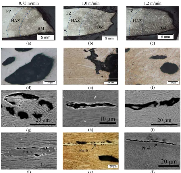
To better understand the tensile deformation, longitudinal sections along the tensile load direction near the failure location were examined for the three welding speeds, as shown in Figure 7. All the tensile specimens failed in the BM but near HAZ5, as observed in Figure 7a-c. A close-up observation in Figure 7d-f demonstrates the presence of some pores near the failure locations which are deformed and/or elongated along the tensile loading direction. The porosity area fractions measured using an image analysis method on the original cast BM and the BM of the weld near the fracture location conducted at a welding speed of 1.0 m/min are, respectively, 0.12 ± 0.04% and 0.73 ± 0.3%, which indicates a noticeable increase in both porosity area and size during the tensile deformation. The observation of larger porosities in a greater number after the tensile failure can be due to (i) the growth of some pre-existing pores in the original cast BM and (ii) formation of new pores during the tensile deformation. The existing pores in the original BM can be gas bubbles and/or shrinkage porosity as shown in Figure 3a and Figure 8, the tensile fracture surface morphologies. Specifically, in Figure 8e, dendrite tips are clearly observed indicating the possible presence of shrinkage porosity in the BM. Clearly, the pre-existing porosity defects in the original cast BM can initiate tensile cracking, accelerate crack propagation, or even change the fracture path.
Generally it was observed that the tensile cracks formed within the martensite matrix, i.e. between the martensite laths (Figure 7g-i) or at the primary delta-ferrite/martensite interfaces (Figure 7j-l). In particular, it was found that at an early stage, multi-cracks form within the martensite matrix (Figure 7g-i) or at the delta-ferrite/martensite interfaces (Figure 7j-k) and propagate, coalesce and link together into longer cracks, as shown in Figure 7h,i,l. The cracking mechanism within the martensite matrix is consistent with the formation of microvoids during tensile loading. The martensite matrix displays dimple features, as shown in Figure 8g-i. The necking appearing near the fracture locations in Figure 7a-c is an indicative of the ductile failure mode, which may involve initiation, growth and coalescence of microvoids during tensile deformation. The same crack generation process has been observed for ferritic-martensitic steels (Avramovic, Saleh, Jain, & Wilkinson, 2009; Kadkhodapour, Butz, Ziaei, & Schmauder, 2011). The differences in the localized deformation between the martensite particles or laths during tensile deformation may lead to separation of the bulk martensite or the martensite laths (Steinbrunner, Matlock, & Krauss, 1988). As for the cracks propagating at the primary delta-ferrite/martensite interfaces, the poor bonding between the two phases may be responsible for the cracking. In addition, incompatibility of the plastic deformation between the primary delta-ferrite and martensite phases may induce local stress concentration, that can further aid interfacial decohesion between the two phases with the crack being aligned along the tensile loading direction. Due to limited quantity of primary delta-ferrite particles available, microvoid formation and growth inside the bulk martensite was predominately observed. In addition, some martensite softening is possible after tempering, which leads to a more homogeneous carbon content between the two phases (primary delta-ferrite and martensite). In particular, Lee et al. (2004) proved through wavelength-dispersive spectroscopy that during tempering diffusion of carbon from martensite to ferrite occurs, which
UTS (MPa) Failure location during tensile testing
Charpy impact energy (J) Specification values ≥ 755I N/A ≥ 27II; ≥ 34III
Welding speed 0.75 m/min 843.0 BM 40.0
Welding speed 1.0 m/min 838.5 BM 41.0
can increase the strength of the primary delta-ferrite and the interfacial strength between the two phases. Hence the cracks formed at the primary delta-ferrite/martensite interfaces propagate into the martensite matrix, rather than in the delta-ferrite, as evidenced in Figure 7j-l.
Charpy Impact Property
The Charpy V-notch impact energies in the FZ of the welds assembled at the three different welding speeds are listed in Table 3. The impact energy values increased slightly with increasing welding speed from 40.0 J at 0.75 m/min to 45.5 J at 1.2 m/min. The minimum requirement according to ASME Sect. VIII, Div.1 and industrial hydraulic turbine manufacturing specification for Charpy impact tests is 27 J and 34 J, respectively. Therefore, all welds have higher Charpy impact energies than the minimum requirement at -18°C. These results indicate that the recommended tempering conditions selected from ASME sec. IX are suitable for sufficiently reducing the dislocation density and internal stresses in the hybrid laser-arc welds through the tempering of martensite and formation of probably some reversed austenite. As mentioned previously, three possible phases are present in the FZ of the tempered hybrid
0.75 m/min 1.0 m/min 1.2 m/min
(a) (b) (c)
(d) (e) (f)
(g) (h) (i)
(j) (k) (l)
Figure 7 Microstructure along the tensile load direction near the tensile fracture surface of the welds assembled at welding speeds of 0.75 m/min (a,d,g,j), 1.0 m/min (b,e,h,k) and 1.2 m/min (c,f,i,l)
100 µ m
FZ FZ FZ
BM BM BM
HAZ HAZ HAZ
the fracture tip undergoes martensitic transformation and acts as a shock energy absorber during the impact testing. Hence, the transformation of austenite to martensite during plastic deformation (transformed induced plasticity mechanism) absorbs additional energy, thereby improving the toughness (Bilmes et al., 2001). On the other hand, the presence of delta-ferrite in a 13%Cr–4%Ni low carbon martensitic stainless steel can deteriorate the impact properties by decreasing the crack initiation and propagation energy and promote decohesion at delta-ferrite/martensite interfaces during fracture (Wang, Lu, Xiao, Li, & Li, 2010).
0.75 m/min 1.0 m/min 1.2 m/min
(a) (b) (c)
(d) (e) (f)
(g) (h) (i)
Figure 8 Secondary electron images of the tensile fracture surfaces for the welds assembled at welding speeds of 0.75 m/min (a,d,g), 1.0 m/min (b,e,h) and 1.2 m/min (c,f,i)
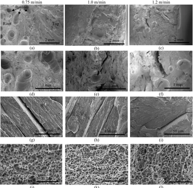
Figure 9 shows the general overviews of the Charpy impact fracture surfaces for the welds assembled at the different welding speeds. The fracture surface topography of the weld assembled at 0.75 m/min exhibits a high amount of porosities in the FZ, especially close to the root (Figure 9a), probably due to the collapse of the unstable keyhole at this low welding speed. At the higher welding speeds (1.0-1.2 m/min), the observed porosity was lower, although some secondary cracks appeared to initiate from the porosity (Figure 9b,c,e,f). The fractographs indicate that the fracture mechanism seems to be a mixture of quasi-cleavage and dimple mode. For instance, the quasi-cleavage facets, as revealed in Figure 9g-i, are associated with tear ridges and suggest that plastic deformation is limited during impact loading of each welding speed condition. In the regions associated with the prior-austenite grains, the quasi-cleavage facets were separated by secondary cracks that exhibited parallel morphologies, which have a similar spacing distance to those observed between two adjacent delta-ferrite stringers in the FZ (Figure 4b). This observation suggests that the secondary cracks most likely propagate along the delta-ferrite stringer/martensite lath interfaces during Charpy impact loading, leading to the formation of quasi-cleavage facets in the FZ. Carrouge et al. (2004) also observed secondary intragranular cracks propagating along the delta-ferrite/lath martensite interfaces during Charpy impact loading of low carbon supermartensitic stainless steel and indicated that, when the dispersed delta-ferrite in the matrix possesses a spheroidised morphology (more analogous to the primary delta-ferrite in the BM), the initiated crack could not link up
20 µm 20 µm 20 µm
Porosity
and propagate as easily. It is noteworthy that the easy crack propagation along the delta-ferrite/martensite interface is consistent with that appearing along primary delta-ferrite plate/martensite interface in the BM during tensile loading of the hybrid laser-arc welds in this study.
By contrast, on the fractographs of each weld, the presence of equiaxed dimples, resulting from the formation and coalescence of microvoids in the matrix, are shown in Figure 9j-l. The fracture surfaces reveal shallower dimple morphologies for the weld assembled at 0.75 m/min as compared to the deeper dimples for the welding speed condition of 1.2 m/min. The deeper dimple morphology represents greater plastic deformation and consequently a higher absorbed energy. As Dieter and Bacon (1986) indicated that the energy absorbed during impact loading increases with decreasing prior-austenite grain size, this can explain the slightly higher impact energy value obtained in the present study at the higher welding speed; in particular, a higher welding speed gives a faster cooling rate that can lead to a finer prior-austenite grain size and consequently finer lath martensite.
0.75 m/min 1.0 m/min 1.2 m/min
(a) (b) (c)
(d) (e) (f)
(g) (h) (i)
(j) (k) (l)
Figure 9 Secondary electron imaging of the Charpy impact fracture surfaces for the welds assembled at welding speeds of 0.75 m/min (a,d,g,j), 1.0 m/min (b,e,h,k) and 1.2 m/min (c,f,I,l)
CONCLUSIONS
Hybrid laser-arc welding (HLAW) of low carbon 13% Cr-4% Ni martensitic cast stainless steel CA6NM was performed at different welding speeds in butt joint configuration. The microstructures and mechanical properties were characterized after post-weld tempering at 600°C for 1 hour.
• The fusion zone in the welded CA6NM alloy in the post-weld tempered condition mainly consisted of a tempered lath martensite matrix with residual delta-ferrite formed at the prior-austenite grain and sub-grain boundaries.
• Four different heat affected zones (HAZs) were distinguishable, each exhibiting a tempered martensite microstructure after post-weld tempering. Coarse tempered lath martensite was observed in HAZ2 as compared to HAZ3, due to the higher temperatures experienced in HAZ2 (i.e. into the single phase delta-ferrite region) on heating during welding. The tempered martensite in HAZ4 and HAZ5 were similar in appearance to that in the base metal under optical and scanning electron microscopy. Reversed austenite and chromium carbides also possibly formed in the HAZ during the post-weld tempering process, though not resolved using optical and scanning electron microscopy in this work. • The average hardness in the tempered fusion zone increased slightly with increasing welding speed
from 291 ± 7 HV at 0.75 m/min to 304 ± 7 HV at 1.2 m/min, due to the refinement of the prior-austenite grains and increased dislocation density. A hardness maximum appeared in HAZ4 near the HAZ3/HAZ4 boundary while a hardness minimum was observed in HAZ5. Hardening in HAZ4 was attributed to the high temperatures experienced during welding that would lead to carbide dissolution and, in turn, carbon supersaturation of the untempered martensite; this pre-condition would result in a harder martensite on tempering. Maximum softening in HAZ5 after post-weld tempering was due to the transformation of untempered martensite to tempered martensite, the formation of reversed austenite, and the double tempering effect of the tempered martensite already existing in HAZ5. • The ultimate tensile strength of all the welds in the tempered condition ranged between 843 MPa and
896.5 MPa, which sufficiently meets the minimum requirement of 755 MPa according to the ASTM A743 specification. The microstructure near the tensile fracture surface and from fractography indicated dimple mode ductile features and the presence of two types of tensile cracks: (i) within the martensite matrix, i.e. between the martensite laths and (ii) at delta-ferrite/martensite interfaces. The predominant cracking mechanism within the martensite matrix is consistent with the formation, growth and coalescence of microvoids during tensile fracture in the base metal of the welds. By contrast, the delta-ferrite/martensite decohesion is probably due to their poor bonding, although interfacial separation may be further aided by the local stress concentration caused by the differing plastic deformability between the delta-ferrite and martensite phases.
• The Charpy notch impact energy values of the tempered welds increased slightly from 40.5 J to 45.5 J with increasing welding speed from 0.75 m/min to 1.2 m/min; these values are well above the current minimum requirements in ASME and turbine manufacturing industrial specifications. The slightly higher impact energy at higher welding speed was attributed to the refined prior-austenite grains. Mixed dimple-quasi cleavage fracture modes were observed with secondary cracks being present along the delta-ferrite/martensite interface in the fusion zone. With increasing welding speed, the dimples on the fracture surface were observed to be deeper, thereby corroborating the higher impact energy values.
ACKNOWLEDGMENTS
The authors are grateful to Alstom, Hydro-Québec and National Science and Engineering Research Council of Canada (NSERC) for the financial supports. The authors also wish to thank E. Poirier and X. Pelletier of NRC Aerospace for their technical assistance during welding and metallographic preparation.
REFERENCES
Akhiate, A., Braud, E., Thibault, D., & Brochu, M. (2014). Carbon content and heat treatment effects on microstructures and mechanical properties of 13%Cr–4%Ni martensitic stainless steel. Conference of Metallurgist, Vancouver, Canada.
Al Dawood, M., El Mahallawi, I., Abd El Azim, M., & El Koussy, M. (2004). Thermal aging of 16Cr–5Ni– 1Mo stainless steel: Part 2–Mechanical property characterisation. Materials Science and Technology, 20(3), 370-374.
Avramovic-Cingara, G., Saleh, C.A., Jain, M., & Wilkinson, D. (2009). Void nucleation and growth in dual-phase steel 600 during uniaxial tensile testing. Metallurgical and Materials Transactions A, 40(13), 3117-3127.
Bilmes, P., Solari, M., & Llorente, C. (2001). Characteristics and effects of austenite resulting from tempering of 13Cr–NiMo martensitic steel weld metals. Materials Characterization, 46(4), 285-296. Candelaria, A., & Pinedo, C. (2003). Influence of the heat treatment on the corrosion resistance of the martensitic stainless steel type AISI 420. Journal of Materials Science Letters, 22(16), 1151-1153.
Caron, R., & Krauss, G. (1972). The tempering of Fe-C lath martensite. Metallurgical Transactions, 3(9), 2381-2389.
Carrouge, D., Bhadeshia, H., & Woollin, P. (2004). Effect of δ-ferrite on impact properties of supermartensitic stainless steel heat affected zones. Science and Technology of Welding & Joining, 9(5), 377-389.
De Sanctis, M., Valentini, R., Lovicu, G., Dimatteo, A., Ishak, R., Migliaccio, U., & Pietrangeli, E. (2013). Microstructural evolution during tempering of 16Cr-5Ni stainless steel: effects on final mechanical properties. Materials Science Forum, 762, 176-182
Dieter, G. E., & Bacon, D. (1986). Mechanical metallurgy (vol.3). New York :McGraw-Hill.
Folkhard, E., Rabensteiner, G., & Perteneder, E. (1988). Welding metallurgy of stainless steels, 98, Springer-Verlag: Vienna.
Hanamura, T., Torizuka, S., Tamura, S., Enokida, S., & Takechi, H. (2013). Effect of austenite grain size on transformation behavior, microstructure and mechanical properties of 0.1 c–5mn martensitic steel. ISIJ International, 53(12), 2218-2225.
Iwabuchi, Y. (2003). Factors affecting on mechanical properties of soft martensitic stainless steel castings. JSME International Journal Series A, 46(3), 441-446.
Kadkhodapour, J., Butz, A., Ziaei-Rad, S., & Schmauder, S. (2011). A micro mechanical study on failure initiation of dual phase steels under tension using single crystal plasticity model. International Journal of Plasticity, 27(7), 1103-1125.
Kimmins, S., & Gooch, D. (1983). Austenite memory effect in 1 Cr–1 Mo–0· 75V (Ti, B) steel. Metal science, 17(11), 519-532.
Krauss, G. (2012). 5 - Tempering of martensite in carbon steels. In E. Pereloma & D. V. Edmonds (Eds.), Phase Transformations in Steels (Vol. 2, pp. 126-150): Woodhead Publishing.
Lee, H. S., Hwang, B., Lee, S., Lee, C.G., & Kim, S.-J. (2004). Effects of martensite morphology and tempering on dynamic deformation behavior of dual-phase steels. Metallurgical and Materials Transactions A, 35(8), 2371-2382.
Lippold, J.C., & Kotecki, D.J. (2005). Welding metallurgy and weldability of stainless steels. John Wiley & Sons : New Jersey.
Mahrle, A., & Beyer, E. (2006). Hybrid laser beam welding—Classification, characteristics, and Applications. Journal of Laser Applications, 18, 169.
Mirakhorli, F., Cao, X., Pham, X.T., Wanjara, P., & Fihey, J.-L. (2014). Hybrid fiber laser–arc welding of 10-mm thick CA6NM stainless steel. Materials Science & Technology 2014 Pittsburgh, PA, USA, 1891-1900.
Morito, S., Huang, X., Furuhara, T., Maki, T., & Hansen, N. (2006). The morphology and crystallography of lath martensite in alloy steels. Acta Materialia, 54(19), 5323-5331.
Porter, D. A., & Easterling, K. E. (1992). Phase transformations in metals and alloys. United Kingdom: CRC press.
Qin, B., Wang, Z., & Sun, Q. (2008). Effect of tempering temperature on properties of 00Cr16Ni5Mo stainless steel. Materials Characterization, 59(8), 1096-1100.
Santella, M., Swindeman, R., Reed, R., & Tanzosh, J. (2001). Martensite formation in 9Cr-1Mo steel weld metal and its effect on creep behavior. EPRI Conference on 9Cr Materials Fabrication and Joining Technologies.
Sarafan, S., Wanjara, P., Champliaud, H., & Thibault, D. (2015). Characteristics of an autogenous single pass electron beam weld in thick gage CA6NM steel. The International Journal of Advanced Manufacturing Technology, 1-13.
Song, Y., Li, X., Rong, L., & Li, Y. (2011). The influence of tempering temperature on the reversed austenite formation and tensile properties in Fe–13% Cr–4% Ni–Mo low carbon martensite stainless steels. Materials Science and Engineering: A, 528(12), 4075-4079.
Song, Y., Li, X., Rong, L., Ping, D., Yin, F., & Li, Y. (2010). Formation of the reversed austenite during intercritical tempering in a Fe–13% Cr–4% Ni–Mo martensitic stainless steel. Materials Letters, 64(13), 1411-1414.
Song, Y.Y., Ping, D.H., Yin, F.X., Li, X.Y., & Li, Y.Y. (2010). Microstructural evolution and low temperature impact toughness of a Fe–13%Cr–4%Ni–Mo martensitic stainless steel. Materials Science and Engineering: A, 527(3), 614-618.
Steinbrunner, D. L., Matlock, D., & Krauss, G. (1988). Void formation during tensile testing of dual phase steels. Metallurgical Transactions A, 19(3), 579-589.
Thibault, D., Bocher, P., & Thomas, M. (2009). Residual stress and microstructure in welds of 13% Cr–4% Ni martensitic stainless steel. Journal of Materials Processing Technology, 209(4), 2195-2202.
Trudel, A., Sabourin, M., Lévesque, M., & Brochu, M. (2014). Fatigue crack growth in the heat affected zone of a hydraulic turbine runner weld. International Journal of Fatigue, 66(0), 39-46.
Vander, V., & George, F., (1984). Metallography, Principles and Practice. New York: ASM International. Wang, P., Lu, S., Xiao, N., Li, D., & Li, Y. (2010). Effect of delta-ferrite on impact properties of low carbon 13Cr–4Ni martensitic stainless steel. Materials Science and Engineering A, 527(13), 3210-3216. Zappa, S., Svoboda, H., & Surian, E. (2013). Supermartensitic stainless steel deposits: effects of shielding gas and postweld heat treatment. Welding Journal, 91(3), 83-90.