VIII. ATOMIC BEAMS
Prof. J. R. Zacharias B. B. Aubrey C. L. Searle Prof. J. G. King D. S. Edmonds, Jr. G. W. Stroke Dr. C. L. Schwartz R. D. Haun, Jr. R. Weiss
J. H. Holloway
RESEARCH OBJECTIVES
For the past ten years this group has devoted its time to observing the physical shapes of atomic nuclei and the motions of their constituent particles. As a first approximation an atomic nucleus can be regarded as a point charge containing most of the atomic mass. The interaction between this point charge and the circumambient electrons involves an energy range from a few volts for the loosely bound electrons to many kilovolts for the electrons in the heavy elements. Higher orders of approximation show that the nucleus
1. spins on its axis and is composed of particles spinning on their own axes; 2. has a finite, small volume in which the neutrons and protons composing it are nonuniformly distributed;
3. has a magnetic moment arising from the translational motion of the protons and from the intrinsic magnetic moments of the neutrons and protons within it;
4. has a nonspherical distribution of electric charge; 5. has a nonspherical distribution of magnetism.
In measurements made in this laboratory, all of these effects appear to be energy differences between energy states so close together that the frequencies of transition (hv) are in the range of contemporary radiofrequency technique. In order to observe some of these effects it is necessary to measure the transition frequencies with very high precision. It has been possible to use one of these transition frequencies as the standard of frequency (in the atomic clock), and the resulting precision has stimulated us to measure other things with great precision. The next step is to measure the veloc-ity of light with improved precision, and this experiment leads to the observation that standards of length are not as precise as they could be and that they certainly do not possess the excellence of frequency measurements. Improvement is hoped for; again, molecular beam techniques will be used. Once length measurements are more precise, it is expected that these same techniques can be used to observe shapes of atomic nuclei that are not otherwise observable.
There are other paths along which precision frequency measurement leads us. We are trying to observe the gravitational red shift, an effect of two parts in 1013. We may also try to observe the epochal dependence of the relation between the three kinds of time - atomic, nuclear, and gravitational.
Associated with all of this work in order to accomplish the objectives listed above are vacuum, frequency generation, mass spectroscopy, surface 'chemistry, molecular beam detection, electron multiplication, and electromagnetic wave propagation tech-niques.
J. R. Zacharias, J. G. King
A. PROPOSED MEASUREMENT OF THE VELOCITY OF LIGHT IN TERMS OF TWO PRIMARY STANDARDS, CESIUM (Cs1 3 3
) AND MERCURY (Hg1 9 8)
This proposal grew out of discussions between Dean George R. Harrison and Pro-fessor Jerrold R. Zacharias, when the interferometrically controlled ruling (1, 2, 3) engine at M.I.T. had been perfected, under the direction of the former, to the point at
198
which measurements of length in terms of the green line of isotope Hg could be rapidly made with a precision of a few ten-millionths of an inch (1 or 2 x 10- 7 inch)
(VIII. ATOMIC BEAMS)
over distances as great as ten inches. Professor Zacharias has designed and perfected a cesium atomic frequency standard (4, 5), using the hyperfine structure line of Cs 1 3 3 at approximately 9, 192, 632 Mc/sec to stabilize the frequency of a microwave signal generator. The accuracy of this frequency standard is known to be about 1 part in
10
10 . By measuring the separation of the end plates of a resonant cavity to a few parts in 108 it should be possible to determine the velocity of light with equal precision.
(See Fig. VIII-1.)
It is difficult to estimate the precision of measurements of the velocity of light that have been reported (6, 7), but we believe that with the new, precise equipment available at M.I.T. it should be possible to improve on the best present values by a factor of at least 100. We believe it possible to measure the velocity of light c to a precision of
1 part in 108
At present there is no coherent source of microwave radiation that will give a satis-factory diffraction pattern or substantially plane waves parallel to the motion of a plate at the accuracy required in measurements of the desired precision. If it were possible to measure length by microwave interferometric methods alone, the microwave wave-length could be used both as a standard of wave-length and as a unit of comparison of wave-length and then optical observations would be unnecessary. The velocity of light could be defined as unity, because frequency measurements can be made easily to an accuracy
12
of 1 part in 10 . Therefore the essence of the proposed method consists in comparing the wavelength of microwaves in a microwave resonator with the wavelength of the green
198
mercury line Hg (5460.7532 A approximately).
Since longitudinal wavelengths in a cavity resonator are dependent on the lateral dimensions of the resonator, it would seem at first sight that precision would be limited by the accuracy of measurement of both length L and diameter D of the resonator. This is not the case, however. For the TE01n modes in a circular cavity (for example, in circular E modes), modes in which the diameter is considerably greater than the length, the effect of the diameter can easily be reduced by a factor of 10 to 100, and therefore the diameter need only be measured with a precision of from 10 to 10
Equation 1 that is fundamental in the present method (8, 9) is
1 + 1
V
( L)-1/2 'Imn 2Q (1)[ 2
+(
1/2
(r
) n+in which v is the velocity of propagation in centimeters per second in the medium; f'lmn is the frequency in cycles per second of the mode, designated by the suffix, at which the cavity is in resonance; D and L are the internal diameter and length, respectively; r is a constant for a particular mode of resonance; n is the number
W, IOp
T
ICE
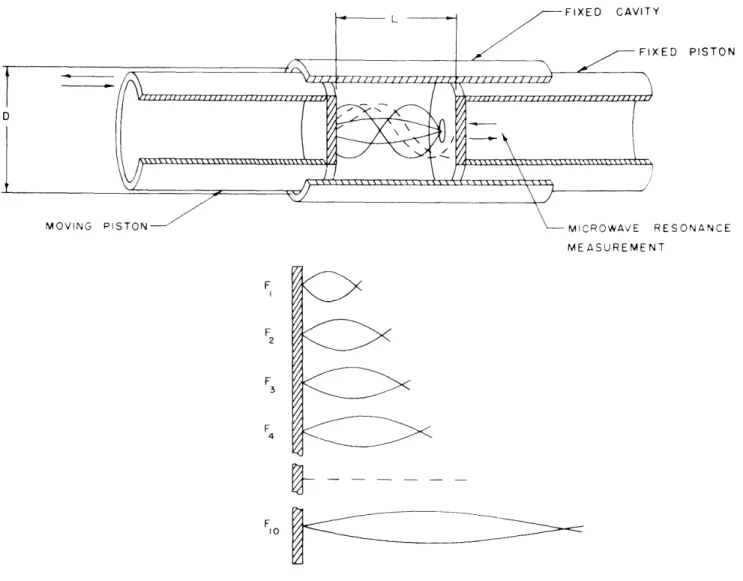
Fig. VIII-1. Schematic diagram of apparatus.
-(VIII. ATOMIC BEAMS)
of half-wavelengths in the resonator,
Q
is
the quality factor; and
sL
and
Eare the
per-meability and the dielectric constant, respectively, of the medium inside the resonator.
Equation 1 shows that the diameter D and length L terms add as the square root of
the sum of the squares and that the larger term predominates. Determination with two
separate frequencies and two measurements of the length L should yield both the
veloc-ity of light c and the diameter D in an ideal case.
The electrical length differs from the mechanical length by skin-depth corrections.
By making the measurements of length between successive electrical nodes so that the
skin-depth correction is the same in all parts of the microwave resonator in both
posi-tions, we can overcome this difficulty.
Therefore, in principle, with a cavity that is a
perfect right circular cylinder having uniform skin depth throughout the wall surface,
two observations should suffice, and one would never have to observe skin depth
at all.
However, the best estimate of precision in the making of a right circular cylindrical
cavity of optical accuracy, made by Dr. James G. Baker of Harvard University,
indi-cates that a fused quartz tube of 6 inches bore and more than 8 inches long can be
obtained cylindrical and straight to a precision of 25 millimicrons. This precision is
somewhat better than that theoretically required for the precision of c that is desired.
The cylinder wall will be uniformly coated with a film of evaporated silver about
3 microns thick, which might be protected by another thin film. The theoretical skin
depth in silver at a free-space wavelength of 3 cm is about 1.65 microns. In order to
obtain this high optical precision, three cylinders must be made at the same time; the
grinding and polishing pistons will be temperature-controlled in order to ensure stable
pressure against the cylinder wall.
End plates will be made flat of Heraeus optical
fused quartz.
If the cylindrical cavity turns out as it is hoped it will, the two measurements
referred to above would just about suffice for the desired precision. But this is too
much to expect.
Therefore, the effective diameter D will be overdetermined by means
of a multiplicity of measurements carried out in two ways.
Method 1.
a. A frequency spectrum of different microwave frequencies
fl, f2P f3,
and so forth,
will be gone through, up to the bandwidth of the microwave bridge used to pick up the
maximum "points".
(See Figs. VIII-2 and VIII-3.)
b.
These measurements will be repeated for a change in frequency of at least a
factor of 2, and if possible of a factor of 10.
It is observed that for a basic central
fre-quency, let us say 9000 Mc/sec, approximately one hundred observations could be
obtained in one run, and that the estimated precision is based on the effectiveness of
one run only.
Repetitive runs at other microwave frequencies will be undertaken to gain
improvement.
Only experiment will decide when this process should be stopped.
ED PISTON ESONANCE MEASUREMENT F F 2 F 3 F 4 7, F
Fig. VIII-2. Diagram showing that during the continuous observation of the motion of one end plate, the microwave frequency will be varied in stages.
Standing-wave pattern for one frequency.
END PISTON
Fig. VIII-4.
Diagram showing how to examine the effect of the cylinder
diameter for a fixed distance between the end plates.
Fig. VIII-3.(VIII. ATOMIC BEAMS)
Method 2.
Note in Fig. VIII-1 that the end plates are supported independently of the outer cyl-inder and are not in contact with it. Therefore, the outer cylinder can be moved longi-tudinally past the end plates. (See Fig. VIII-4.) In other words, the cavity will be moved
with respect to the fixed, cylindrical end piston. This process is designed to give a measure of the irregularities in the cylindrical cavity, by measuring microwave-frequency resonance as a function of distance along the axis of the cylinder. Measure-ments of this sort can be made with modes that emphasize the diameter effect itself. They provide another set of equations for D.
It would seem that with this powerful method of making determinations and correc-tions of diameter D, a crude cylinder is all that is needed, but only experimenting with the contemplated good cylinder will show the effects of lack of precision in the dimen-sions of the cavity.
The nature of the contemplated apparatus, as well as of the parts already in exist-ence, is such that automatic operation, with its inherent advantages of controllable and reproducible procedures, is possible.
It is expected that the apparatus will be run occasionally over a long period of time to determine the dependence of the velocity of light on epoch.
1. Q Corrections (9)
As indicated above, first-order dissipation effects are obviated by the method of measurement itself. There are, however, two dissipation corrections that vary as
I/Q
2One is the effect that shifts the peak of any resonance curve away from the natural reso-ance by the square of the dissipation term. The other is a more subtle correction that arises because the modes of oscillation of the cavity are computed by superposition of plane waves of uniform amplitude moving obliquely in it. Since energy is being drained off into the wall, the amplitudes of these plane waves are not uniform. It can be shown that this correction also varies as I/Q . A detailed correction of this effect has not
been made, but it is expected that it can be calculated.
Q
is likely to be about 105 10 Therefore, these inverse-square corrections should be only a few parts in 10102. Spurious Modes
It is hoped that the microwave resonances can be excited in such a pure way that effects of neighboring modes will be minimized. The possibilities of exciting pure circular E modes without exciting any other modes are limited by the bandwidth to be used in the observations. A compromise on this point has not been struck. The pres-ence of spurious, long-tailed modes may tend to shift the observed maxima of the reso-ance in question, but with a Q of 105 the line splitting need be only 1 part in 103 to achieve an accuracy of 10-8.
(VIII. ATOMIC BEAMS)
3. Length Measurements
The use of light waves for dynamic length measurement with an interferometrically controlled uniform motion has been successfully demonstrated with the M.I.T. ruling engine (1, 2, 3).
Precisions of 1/200 of a wavelength at 5460.7532 A, or about 1 x 10- 7
inch in 10 inches, will lead to the precisions of 1 part in 108, which we hope for in this experi-ment. The use of the green Hg 1 9 8 wavelength for the measurements avoids numerous steps involved in all other length measurements in which reference has to be made to the standard meter bar. It is well known that the meter bar itself cannot be used for com-parison with any wavelength to precision greater than 1 in 3 x 10⁶
The length L of the microwave cavity will therefore be measured automatically on the controlled ruling engine by means of an interferometer system. One of the end plates of the cavity will be mounted on a carriage that moves continuously at a uniform rate which is measured by an interferometric servo control. A precision of 1/40 wave-length, or 2.5 x 10- 7 inch, has already been demonstrated; by cooling the Hg 1 9 8
light source, excited by means of a high-frequency electrodeless discharge, it should be possible to exceed this precision by the time the cylindrical cavity is ready for use. The position of the end plates will thus be determined by an interferometric optical contact, directly at the plate surface used as an element in the interferometer if
pos-sible, rather than by a mechanical contact, such as the one used with a micrometer screw, for example (8).
The position of the end plate will be determined while the plate is in a state of uni-form motion (3), in order to avoid elastic deuni-formation on stopping and starting. The measuring speed near the resonance maxima might be the present one used for ruling gratings, which is about 0. 1 inch per hour. Between measuring regions the possibility of speeding up the carriage, up to 4 inches per hour, without loss of the fringe count, integral and fractional, through vibration, has been demonstrated. The continuous uni-form motion of the carriage and end plate is an important factor in the elimination of the uncertainties found in static measurements and accelerated displacements, when precisions of fractions of a micro-inch are sought. The static measurements that will be avoided in the present experiment are known to have led to appreciable losses in precision in previous resonant-cavity length measurements.
It is important that the length measurements be obtained for a pure translatory motion. This can be achieved by obtaining interferometric information about the rota-tion of the carriage to a precision of 1/500 second of arc with a double interferometer
(VIII. ATOMIC BEAMS)
4. Index of Refraction of Gas in the Interferometric System
At first sight, it might seem desirable to perform the experiment with electromag-netic radiations in vacuo. The index of refraction of air at 00C and 760 mm Hg is approximately 1.000293; for helium, with which we plan to fill the cavity, it is approxi-mately 1.000034.
In the contemplated measurements, however, we need to know the ratio of the refrac-tive index of the gas for microwaves to that for visible light. With inert molecules like helium these refractive indices for visible and microwave frequencies are almost
the same, and a direct observation of their ratio can be made in a subsidiary appa-ratus to a precision much greater than this experiment calls for. This can be done by observing a microwave-frequency shift and a visible light fringe shift obtained by changing the ambient pressure in a static cavity. An electronic servo system for measuring shifts in slowly moving interference fringes to a precision of perhaps 1/200 wavelength at X 5460 has been designed at M.I.T. by J. Peters and G. W. Stroke (10)
-9 and the microwave-frequency shift can be measured to the high accuracy of 1 x 10 referred to above. There should be no difficulty from this source.
5. Choice of Microwave Frequency
The choice of the particular microwave-frequency range at about 9000 Mc/sec is governed by two factors. One is that of practicability. Electronic equipment operates reliably at these frequencies within the needed precision. The other is the decrease of skin-depth corrections with the increase in frequency. Purity of mode and the actual dimensions of the contemplated cavity seem theoretically favorable for this frequency band. However, we plan to give further theoretical consideration to the central-frequency band, in order to ensure optimum separation of neighboring modes from the one for which resonance is being measured.
6. Choice of Optical Wavelength
The choice of the green mercury line of the isotope Hg198 at 5460.7532 A excited in an electrodeless high-frequency discharge is governed by interferometric considerations. Because of the sensitivity curves of the photomultiplier tubes and filters available at the present time, an intense monochromatic wavelength in the visible range from 3200 A to
6500 A must be used. The interference-fringe contrast or modulation obtainable with a monochromatic, single isotope source is a function of the line half-width that is inversely proportional to the square root of the atomic weight. For this reason the Hg1 9 8 source
is superior to both the krypton (Kr 8 4 and Kr 8 6) and the cadmium (Cd 1 4
)
sources. Furthermore, the mercury spectrum is much simpler than the krypton spectrum, the only neighboring lines at approximately 5770 A and 5790 A leaving, even when used with(VIII. ATOMIC BEAMS)
a simple absorption filter, a residual modulation the effect of which is only of the order
of 1/200 wavelength (at 5461 A) when used in a photoelectric interferometric system (3).
This effect might easily be reduced still more by means of an improved interference
filter, if the need arises.
J. R. Zacharias, G. R. Harrison, G. W. Stroke,
S. J. Mason, C. L. Searle
References
1.
G. R. Harrison and J. E. Archer, J. Opt. Soc. Am. 41, 495 (1951).
2.
G. R. Harrison, G. W. Stroke, and E. Klippenberg, J. Opt. Soc. Am. 44, 347
(1954).
3. G. R. Harrison and G. W. Stroke, J. Opt. Soc. Am. 45, 112 (1955).
4.
J. R. Zacharias, J. G. Yates, V. Jaccarino, J. G. King and associates, Quarterly
Progress Report, Research Laboratory of Electronics, M.I.T., Oct. 15, 1954,
pp. 30-37
5.
J. R. Zacharias, J. G. Yates, and R. D. Haun, Jr., Proc. IRE 43, No. 3, 364
(1955).
6.
L. Essen, Proc. Roy. Soc. (London) A 204, 260 (1950).
7.
E. F. Florman, J. Research NBS 54, 335 (1955).
8.
L. Essen and A. C. Gordon-Smith, Proc. Roy. Soc. (London) A 194, 348 (1948).
9.
J. Bernier, Onde Elect. 26, 305 (1946).
10.
J. Peters and G. W. Stroke, J. Opt. Soc. Am. 43, 668 (1953).
11.
Unpublished results.
B.
MEASUREMENTS OF LENGTH
It may turn out in the measurement of the velocity of light described in section A
that the limit of precision may be the length measurements rather than the frequency
measurements.
In order to improve length measurements and thereby the standard of
length, it is necessary to improve the sharpness of the spectral line at which the
obser-vations are made.
There are three causes of spectral-line broadening in the visible
and in the near-visible regions: Doppler effect, collision broadening, and natural
radi-ation damping. The third cause is inherent in the energy levels of the spectral line
chosen; the first and the second can be reduced by a large factor with the aid of a
molecular beam.
The precision of measurement is limited by the linewidth because the observation
of length involves moving one plate of an interferometer system out to extreme path
difference, where the clarity of the fringes is lost because of overlapping orders of the
many wavelengths of light. Thus the sin2(27rx/2) dependence is smeared out just as
fringes of white light of small path difference are smeared out.
Naturally, one method
(VIII. ATOMIC BEAMS)
of alleviating this difficulty is to reduce the linewidth of the source; this is being tried by other groups in the Laboratory. Another method involves observing the light with a narrow filter.
The narrowest filter consists of a beam of atoms passing at right angles to the light. For many years experiments have been performed in which a beam of atoms is used as a light absorber to reduce Doppler and collision broadening. The present
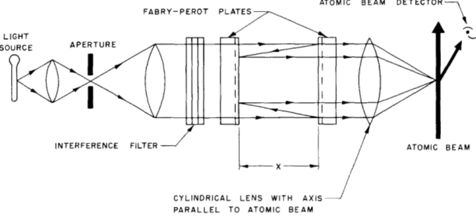
suggestion is to observe the effect of the light on the motion of the atoms. If an atom in the beam absorbs a photon of energy hv it must also absorb its momentum hv/c, which in most cases is enough to project an atom sideways. If, then, the detector of the atoms is placed at the position for receiving the deflected atoms, the presence of radiation can readily be seen. See Fig. VIII-5. Thus the sin2(2wrx/2) dependence of the interferometer light will be observed in spite of the presence of photons of many nearby wavelengths filling up the minima. Any narrow-band filter would be as useful, but the beam of atoms is the narrow-band filter with good signal-to-noise ratio.
The 2537 A line of mercury in absorption arises from the ground state. It may be possible to use it to improve length measurements by two orders of magnitude. The
spectra of other elements look even better, and a choice will be made before starting preliminary experiments.
There are many other mechanisms for making the motion of the atoms sensitive to the absorption of photons from the incident light. If the ground state of the atom has a magnetic moment it is easy to arrange a magnetic-state selector to refocus atoms only when their magnetic state is altered, as it would be by the absorption of a photon. A simple extension of this method would be to turn the whole idea around and measure properties of the energy levels of the atoms of the beam by observing how their motion is affected by the light through the interferometer.
J. R. Zacharias
FABRY-PEROT PLATES
LIGHT
SOURCE APERTURE
I
INTERFERENCE FILTE ATOMIC BEAM
PARALLEL TO ATOMIC BEAM
Fig. VIII-5.
Schematic diagram of apparatus for crossing
a light beam with a molecular beam.
(VIII. ATOMIC BEAMS)
C.
THEORY OF HYPERFINE STRUCTURE
The program of machine calculations described in the Quarterly Progress Report
of October 15, 1955, pages 38-40, has been completed, having used approximately
twenty-three hours of machine time. The nraw" numerical results are presented in
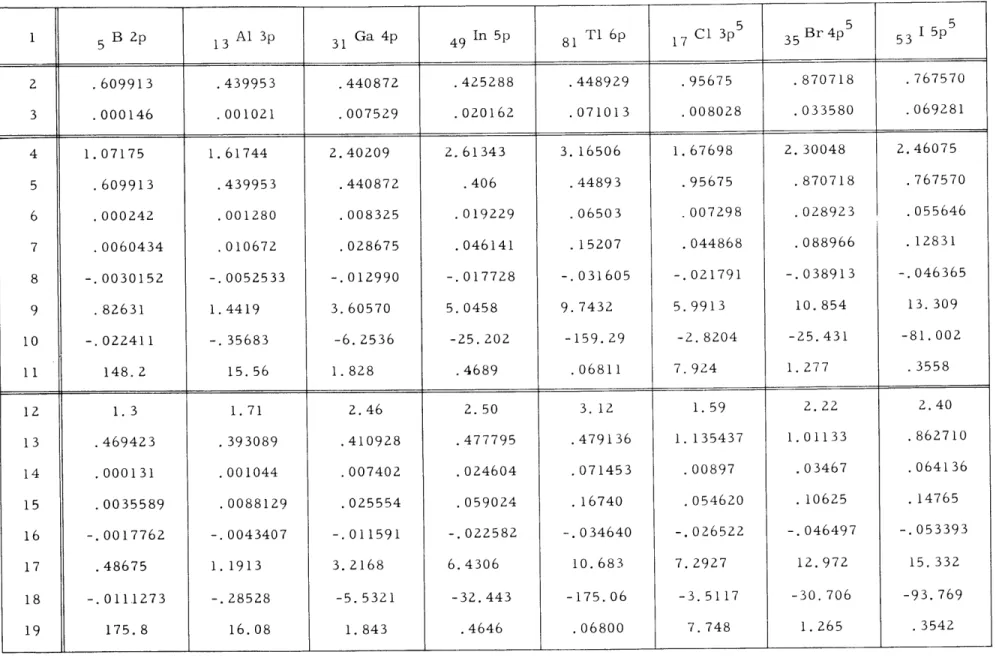
tabular form, and the following discussion refers to lines and columns in Table VIII- 1.
Atomic number, element, and the electronic p-doublet studied are given in line 1.
Line 2 contains
E1/2'
the experimental term value of the pl/
2
state measured in
Rydbergs; and line 3 gives 6, the experimental fine-structure splitting of the
dou-blet, measured in Rydbergs. Lines 4-11 and 12-19 contain, respectively, the results
of the complete calculation for two different values of the atomic potential in the
order:
p
(the potential parameter),
E1/2' 6,
N
- 1fg r
- 2dr (pl/
2),
N
- 1fg r
- 2dr (P3/2)'
0 0 00 fg r 2 dr (Pl/2)0
(for the initial amplitude g(0.0001) = 0.01). N is the normalization integral
00
(f2 + g2) dr
0
and all lengths are in units of the Bohr radius. The value of the fine-structure constant
used was 1/137.
All of the hyperfine-structure integrals do, of course, depend upon the potential
and we must first decide on the correct potential to be used and then take the final
results by interpolation. But before doing this some information can be obtained
imme-diately in the form of ratios of the calculated quantities which are found to be only
slightly dependent on the atomic potential. The ratios of interest are
Table VIII- 1 5 5 5 1 5 B p 13 Al 3p 31 Ga 4p 4 9 In 5p 81 T1 6p 1 7 C1 3p 3 5 Br4p 5 3 I5p 2 .609913 .439953 .440872 .425288 .448929 .95675 .870718 .767570 3 .000146 .001021 .007529 .020162 .071013 .008028 .033580 .069281 4 1.07175 1.61744 2.40209 2.61343 3.16506 1.67698 2.30048 2.46075 5 .609913 .439953 .440872 .406 .44893 .95675 .870718 .767570 6 .000242 .001280 .008325 .019229 .06503 .007298 .028923 .055646 7 .0060434 .010672 .028675 .046141 .15207 .044868 .088966 .12831 8 -.0030152 -.0052533 -.012990 -.017728 -. 031605 -. 021791 -. 038913 -.046365 9 .82631 1.4419 3.60570 5.0458 9.7432 5.9913 10.854 13.309 10 -. 022411 -. 35683 -6.2536 -25.202 -159.29 -2.8204 -25.431 -81.002 11 148.2 15.56 1.828 .4689 .06811 7.924 1.277 .3558 12 1.3 1.71 2.46 2.50 3.12 1.59 2.22 2.40 13 .469423 .393089 .410928 .477795 .479136 1.135437 1.01133 .862710 14 .000131 .001044 .007402 .024604 .071453 .00897 .03467 .064136 15 .0035589 .0088129 .025554 .059024 .16740 .054620 .10625 .14765 16 -.0017762 -.0043407 -.011591 -.022582 -.034640 -. 026522 -.046497 -.053393 17 .48675 1.1913 3.2168 6.4306 10.683 7.2927 12.972 15.332 18 -. 0111273 -.28528 -5.5321 -32.443 -175.06 -3.5117 -30.706 -93.769 19 175.8 16.08 1.843 .4646 .06800 7.748 1.265 .3542
(VIII. ATOMIC BEAMS) 0c N fg r dr (pl/2) 2 o - 00
F
1 (Casimir notation) -1 -2 2N I fg r 2 dr (P3/2) 00 S-If
(f2 + g2) r-3 dr (p32F'
274 00f0
fg
r
-2dr (p
3/
2 00 -4 T' 3~'
fg r-4 dr (p3 / 2) F' 2 00 2Z2J
fg r 2 dr (p3/2 HZ H 45.69 6 F N fg r2 dr (3/2Values for these ratios (relativistic correction factors) based on approximate analytic wavefunctions have been given earlier (1). The greatest difference between our present work and the earlier work is in the factor T'/F', which is used for the octopole study. As a consequence of these new results, the octopole moments of nuclei already meas-ured are now seen to be 25-30 per cent larger than earlier values indicated.
Another quantity roughly independent of the potential is the dipole integral in the P1
/
2 state for a given amplitude of the wavefunction at r - 0 (lines 11, 19). This is related to the "b" coefficient needed in the analysis of hfs anomalies (2). These b coefficients were calculated earlier, using again the approximate analytic wavefunctions that completely neglect the shielding of all other electrons, and we found that these earlier values had to be reduced (for the Pl/ 2 states) by the factors: 1.68 Al; 1.49 Cl; 1.38 Ga; 1.30 Br; 1.22 In; 1.19 I; and 1.10 T1.To get the precise values of the single electron hfs integrals, and not just ratios, we fix the potential for each atomic state at that value which gives a calculated fine-structure 5 which corresponds to the experimentally measured splitting. According to Sternheimer (3) there are polarization contributions to the single-electron fine-structure similar to those he calculated for magnetic dipole and electric quadripole hyperfine structure. However, we have shown (4) that this correction to the
fine-structure is identically zero in the lowest order, so we shall neglect it.
What we do have to make correction for are the exchange matrix elements of the mutual magnetic interactions between the electrons (5) which are not taken into account
(VIII. ATOMIC BEAMS)
in our model of one electron moving in a fixed central field. The relative importance of this correction is as I/Z; therefore, we shall undertake a detailed calculation of Hartree-Fock wavefunctions for the light boron atom in order to check this theory (6). For the heavier atoms a calculation using the simplest analytic form of wavefunction gives a correction to the fine-structure of -11 r-3> cm with an estimated theoreti-cal uncertainty of 15-20 per cent.
With the corrected single-electron fine-structure as our criterion we can now inter-polate from the calculations the best one-electron values of the various hfs integrals. By comparing calculations with measurements we can deduce the values of the magnetic polarization correction factor Rm of Sternheimer (3):
(measured dipole hfs)
(measured nuclear moment) (calculated one-electron dipole hfs) x (1 + Rm) (measured nuclear moment)
The calculation of R includes contributions from several modes of excitation of m
electrons in perturbation theory. Since, for most of the atoms studied, we have two values (7) of Rm (for the P1
/2
and P3/ 2 states), we can make them describe two dif-ferent modes of excitation. We choose the two which, from Sternheimer's work, seem to be the most important, namely, (s - s'), for which the contribution to Rm is -50 times stronger in the P3/ 2 state than in the pl/ 2 state, and (p -* p', P ), for which the contribution is the same in both states.The alternative excitation of s-electrons (s - d) is apparently important in boron (3) (this will also be checked in the aforementioned detailed calculations (6) on this atom) but we shall ignore it in heavier atoms. Verification of this assumption comes from the excellent quantitative agreement between predictions of this form of the theory (2) and experiments (8) on the hfs anomalies in p-states. These anomalies depend on the amount of (s -- s') admixture; and the calculation of the (s - s') admixture would be affected if there were appreciable amounts of (s- d), although it is not affected by the (p - p', P ) mode.
The formulas for calculating the amount of (s - s') contribution to Rm have already been given (1) and they are not changed by the present calculations. This depends only on the experimental ratio a1/2/a3/ 2; by making similar comparisons Sternheimer found that his calculated correction factors were too large (by about a factor of 6 in boron and chlorine).
Our results for the radial mode (p - p', P ) contributions to Rm are (in percentages): (-4 + 4) Al; (-2 + 3) Cl; (+-2 1) Ga; (+3.5 ± 0.5) In; and (+5.2 ± 0.1) TI, where finite nuclear size effects may somewhat alter the value for thallium. The only comparable values calculated by Sternheimer are +17 for Al and +47 for Cl. The comparison leads us to suggest that the wavefunctions used by Sternheimer were too inaccurate for his calculations, and that polarization corrections to magnetic hyperfine structure, except
(VIII. ATOMIC BEAMS)
for the famous s - s' terms, are generally negligible (Z 5 per cent). However, the extension of this negligibility to polarization corrections for quadripoles and higher moments cannot safely be made without a considerable amount of further work.
C. L. Schwartz
References 1. C. L. Schwartz, Phys. Rev. 97, 380 (1955). 2. C. L. Schwartz, Phys. Rev. 99, 1035 (1955).
3. R. Sternheimer, Phys. Rev. 86, 316 (1952); 95, 736 (1954).
4. The details of this and of other theoretical discussions are being prepared for publication.
5. G. Araki and S. Noma, Proc. Phys. Math. Soc. Japan 20, 746 (1938).
6. This work is being carried out by R. K. Nesbet and R. Watson of the Solid State and Molecular Theory Group at M.I.T.
7. Measurements in the P1/2 states are lacking for all the halogens except chlorine, where the ratio a1/2/a 3/2 shows that there is almost no effect from the (s - s') excitation. In order to see how this effect may increase with Z, a measurement of the hyperfine structure Av of Pl/ 2 in iodine is being attempted by R. Onaka of the M.I.T. Spectroscopy Laboratory.
8. In addition to the results on gallium discussed in ref. 2, recent work has been done on thallium by A. Lurio, A. Prodell, and G. Gould at Columbia University. The author is grateful to them and to Prof. P. Kusch for informing him of their unpub-lished experimental results.