A Configurable 3-Phase Machine for Laboratory Instruction
byEric Gregory Tung
Submitted to the Department of Electrical Engineering and Computer Science in partial fulfillment of the requirements for the degree of
Master of Science in Electrical Engineering and Computer Science at the
MASSACHUSETTS INSTITUTE OF TECHNOLOGY
June 2006
@
Eric Gregory Tung, MMVI. All rights reserved.The author hereby grants to MIT permission to reproduce and distribute publicly paper and electronic copies of this thesis document in whole or in part.
Author...
De ent of Electrical Engineering and Computer Science June 2, 2006
Certified by. ...
Steven B. Leeb Professor of Electrical Engineering Thesis Supervisor Certified by... (1-1 Accepted by...K ... James L. Kirtley, Jr. Professor of Electrical Engineering Thesis Supervisor
... Arthur C. Smith Chairman, Department Committee on Graduate Students
MASSACHUSETTS INSMTUTE, OF TECHNOLOGY
A Configurable 3-Phase Machine for Laboratory Instruction by
Eric Gregory Tung
Submitted to the Department of Electrical Engineering and Computer Science on June 2, 2006, in partial fulfillment of the
requirements for the degree of
Master of Science in Electrical Engineering and Computer Science
Abstract
In order to learn about and work effectively with electromechanical systems, many stu-dents need exposure to these systems before completing their education. This thesis work introduces two novel teaching aids for laboratory classes. The first is a 3-phase axial-flux machine which can be configured as a permanent-magnet or induction machine with moder-ate effort for teaching about power electronics. The second is an introductory robot which demonstrates and controls electromagnetic actuators for teaching an introductory freshman class.
Thesis Supervisor: Steven B. Leeb Title: Professor of Electrical Engineering Thesis Supervisor: James L. Kirtley, Jr. Title: Professor of Electrical Engineering
Acknowledgments
I would like to thank Professors Leeb and Kirtley for their assistance, advice, patience, and guidance over the course of this thesis. This thesis was made possible by essential funding from the Cambridge-MIT Institute and the Grainger Foundation. The material herein would not have been possible without the prior work of fellow graduate students Andrew Thomas and Mariano Alvira. Warit Wichakool, Greg Belote, and Clinton Buie helped design important subsystems, and along with Alex Crumlin and Candace Wilson, helped with construction. Finally, I'd like to thank all my family and friends for their support.
Contents
1 Introduction
1.1 3-Phase Machine . . . . 1.2 Robot . . . . ... ... .. . . . .
2 3-Phase Machine Mechanical Description 2.1 Introduction ...
2.2 Preliminary Calculations ... 2.3 The Design Process ... 2.4 Peripherals .... ... 2.4.1 Torque Arm ... 2.4.2 Position Encoder . . . . 2.4.3 Motor controller . . . . 2.4.4 Drive Motor . . . . 2.4.5 Tri-Totem Board . . . . 2.5 U sage . . . . 2.5.1 Permanent Magnet . . . . 2.5.2 Induction . . . . 2.5.3 Generator . . . . 2.5.4 M otor . . . . 2.6 Future Improvements . . . . 2.6.1 2.6.2 2.6.3 2.6.4
Radial Wall Compliance Mounting Grid . . . . . Standardized Screw Size Fully Symmetric Rotors
15 35 . . . . . . . . . . . . . . . .
3 3-Phase Induction Machine Electrical Description 3.1 Introduction. ... ...
3.2 3-phase Induction Model . . . . 3.3 Improved Single Phase Model . . . . 3.4 Analytical Analysis . . . . 3.4.1 Armature winding resistance . . . . 3.4.2 Distributed Winding . . . . 3.4.3 Magnetizing Inductance . . . . 3.4.4 Leakage Inductance . . . . 3.4.5 Rotor Resistance . . . . 3.5 Measurement and Comparison . . . .
4 3-Phase Permanent Magnet Machine 4.1 Introduction . . . . 4.2 3-phase Permanent Magnet Model . 4.3 Sinusoid vs. Tri-totem . . . . 4.4 Measurement . . . .
5 Robot Mechanical Description
5.1 Introduction . . . . 5.2 The Design Process . . . . 5.2.1 Card Rack . . . . 5.2.2 Wheel Base . . . . 5.3 Peripherals . . . . 5.3.1 Circuit Prototyping: Green Bc 5.3.2 Microcontroller: Basic ATOM 5.3.3 Movement: Top Board . . . .
5.3.4 Navigation: LC-resonant wire 5.3.5 Data Collection: Hobo . . . . 5.3.6 Data Collection: Current Sens 5.4 Future Improvements . . . . 5.4.1 Wheel Traction . . . . Electrical Description 65 . . . . 6 5 . . . . 6 5 . . . . 6 9 . . . . 7 0 75 . . . . 7 5 . . . . 7 5 . . . . 7 5 . . . . 7 7 . . . . 7 9 )a rd . . . . 7 9 . . . . 8 0 . . . . 8 1 . . . . 8 3 . . . . 8 4 o rs . . . . 8 5 . . . . 8 5 . . . . 8 5 37 37 . . . 37 . . . 39 40 41 42 43 48 53 56
6 Assessment and Conclusion 87
6.1 3-Phase Induction Machine Objectives ... ... 87
6.2 3-Phase Permanent Magnet Machine Objectives . . . . 88
6.3 Robot Objectives . . . . 88
6.4 Checkoff Sheets . . . . 88
A 3-Phase Machine Mechanical Drawings 93 B Datasheets 107 C Controller Parts and Schematics 113 C.1 Position Encoder . . . . 113
C .1.1 B ase . . . . 114
C.1.2 Sensor Board . . . . 114
C.1.3 Encoder W heel . . . . 115
C.2 M otor Controller . . . . 117
D Vendor Contact Information 121 E Armature Construction Instructions 125 E. 1 Preparation . . . . 125
E.2 W ind Segm ents . . . . 126
E.3 Connect Segments . . . . 128
E.4 3-phase Connection . . . . 128
E .5 Flux Check . . . . 129
F Permanent Magnet Machine Assembly Instructions 131 G Induction Machine Assembly Instructions 137 H Induction Machine Analysis Scripts 143 H.1 Amplitude and Phase Extraction: fa3.m . . . . 143
H.2 Error From Sinusoid: err.m . . . . 144
H.3 Deriving Parameters From Data: fanal.m . . . . 144
H.4 Error From Data: derr.m ... ... 145
H.6 Comparing: fresp.m . . . . 149
I Permanent Magnet Machine Analysis Scripts 151
I.1 Motor Constant Identification Via Speed-Voltage:
speed-voltage.m ... ... 151 1.2 Error From Speed-Voltage Line:
speed-voltage.err.m . . . . 152 1.3 Motor Constant Identification Via Torque-Current:
torque.current.m . . . . 152 1.4 Error From Torque-Current Line:
torque-current.err.m . . . . 152 1.5 Motor Constant Identification Via Voltage-speed:
gen.voltage-speed.m . . . . 153 1.6 Error From Generator Voltage-Speed Line:
gen-voltage-speed-err.m . . . . 153
J Robot Mechanical Drawings 155
K Robot Controller Parts and Schematics 169
K .1 Top Board . . . . 170 K .2 2 kHz Generator . . . . 173 K .3 LC Sensor Board . . . . 175
List of Figures
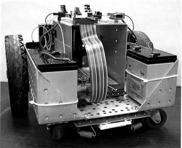
1-1 Photograph of the 3-phase teaching machine . . . . 16
1-2 Photograph of the robot . . . . 17
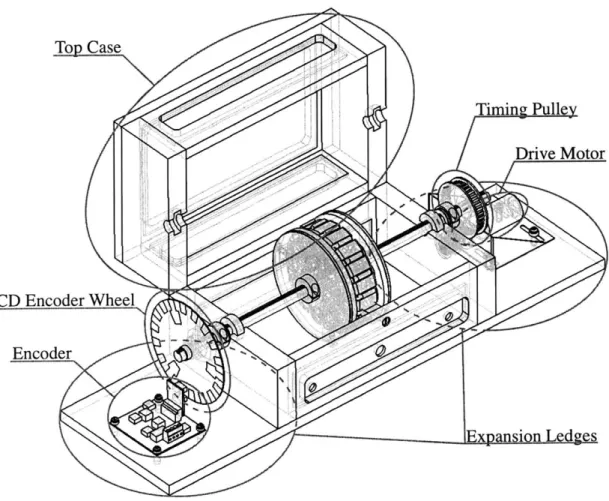
2-1 Wireframe view of the final motor design showing various features . . . . . 20
2-2 Important dimensions of the stator . . . . 22
2-3 Unrolled section of stator showing armature winding pattern . . . . 23
2-4 Shaded detail view showing features of stator/rotors in the permanent mag-net configuration . . . . 25
2-5 Combination guide for winding segments and stator support . . . . 26
2-6 Detail view of bearings . . . . 27
2-7 Torque Arm. Holes allow attachment of a spring scale. . . . . 27
2-8 Encoder wheel: outer track is CLOCK, inner track is RESET . . . . 28
2-9 Schematic of encoder circuit, designed by Warit Wichakool . . . . 28
2-10 Motor controller schematic . . . . 29
2-11 Example waveforms generated at various points in the motor controller . . 30
2-12 Detail view of drive motor peripheral. Timing belt not shown . . . . 31
2-13 3-phase totem controller, based on design by Mariano Alvira . . . . 32
2-14 Axial misalignment of the top and bottom cases . . . . 34
2-15 Complementary rotors: (a) asymmetric; (b): fully symmetric . . . . 36
3-1 Simple model of a 3-phase locked induction machine . . . . 38
3-2 Physical arrangement of a single phase inductor vs. balanced 3-phase inductors 38 3-3 Improved 3-phase model for the locked induction machine . . . . 39 3-4 Single phase of the improved model from the viewpoint of the voltage source 40 3-5 Cross section of stator, showing two turns of armature winding decomposed 41
3-6 Progression from single wire to distributed winding . . . . 42
3-7 Electrical winding angle . . . . 43
3-8 Typical solenoid . . . . 44
3-9 Simplified cross-sectional sketch of magnetic field . . . . 45
3-10 Simplified cross-sectional sketch of rotor and stator . . . . 45
3-11 Sketch of flattened, simplified rotor and stator, part of one phase . . . . 47
3-12 Sketch of flattened coordinate system of interest, only currents on top face are show n . . . . 48
3-13 Dimensions of interest, one phase highlighted . . . . 49
3-14 Contour for flux due to rotor current . . . . 54
3-15 Sample data resulting from f a3. m showing voltage and current for a single phase at 300 H z . . . .
57
3-16 Sample best-fit model generated by f anal. m and data from locked medium rotors ... ... ... ... ... . 59
3-17 Sample predicted 5A-limited torque-speed curve generated by tmot.m . . 61
3-18 Sample predicted 12V-limited torque-speed curve generated by tmot .m . . 62
3-19 Sample comparison between measured data and calculated parameters gen-erated by
fresp.m
. . . . 634-1 3-phase model for the permanent magnet machine . . . . 66
4-2 Model for a single phase of the permanent magnet machine . . . . 66
4-3 Simplified cross-sectional sketch of magnetic field with magnets added . . . 67
4-4 Model of the brushless 3-phase PM machine . . . . 69
4-5 Sketch of 3-phase current from tri-totem vs. rotational angle . . . . 70
4-6 Generated Voltage vs. Drive Speed [rad/sec] . . . . 71
4-7 Maximum torque vs. DC current . . . . 72
4-8 Rotational speed vs. DC voltage . . . . 73
5-1 Wireframe view of the final robot design . . . . 76
5-2 Sketch of final card rack design . . . . 77
5-3 Sketch of wheel lock . . . . 78
5-4 Two motor configurations, configuration (a) also shows a possible battery placem ent . . . . 79
5-5 Picture of green board, designed by Mariano Alvira . . . . 80
5-6 Schematic of top board . . . . 82
5-7 Schematic of 2 kHz generator . . . . 84
5-8 Schematic of LC sensor . . . . 84
5-9 Picture of current sensor . . . . 85
6-1 Sample evaluation sheet for the 3-phase induction machine . . . . 89
6-2 Sample evaluation sheet for the 3-phase permanent magnet machine . . . . 90
6-3 Sample evaluation sheet for the robot . . . . 91
E-1 Winding guide; one side marked for winding direction consistency . . . . 126
E-2 Half-wound segment showing direction of winding . . . . 126
E-3 Tape keeps the segment from shifting as you wind other segments . . . . 127
E-4 Two finished, taped segments . . . . 127
Chapter 1
Introduction
People are increasingly dependent on a web of electrical and electronic devices. One end of this web is the initial power generation from various mechanical sources. Electrical energy is also used to power essential electromechanical actuators. In order to learn about and work effectively with these systems, many students need exposure to electromechanical systems before completing their education. This thesis work introduces two novel teaching aids for laboratory classes, one focusing on 3-phase power electronics, the other focusing on an introductory robotics application for demonstrating and controlling electromagnetic actuators.
1.1
3-Phase Machine
In applications where power density is important, such as power generation or industrial machinery, 3-phase machines are preferred over single-phase machines. Students rarely have experience with 3-phase devices. In Chapter 2 we describe the design of a 3-phase axial-flux machine for laboratory instruction. The machine is configurable as a motor or generator and as an induction or permanent magnet synchronous machine. Chapter 3 describes the electrical characteristics of the 3-phase machine when configured as an induction motor. Chapter 4 describes the electrical characteristics of the 3-phase machine when configured as a permanent magnet synchronous motor. This teaching machine was successfully used in a power electronics class at MIT to teach about 3-phase power and power electronic motor drivers.
Figure 1-1: Photograph of the 3-phase teaching machine
1.2
Robot
Robotics is a rapidly growing field. From small vacuum cleaners to large autonomous vehicles, robots are an increasingly visible application of technology. At the same time, robots can be excellent, fun vehicles for education as shown by the success of classes such as 2.007, 6.270, and MASLab at MIT and national competitions such as FIRST and RoboCup. Robotic products excite students and are terrific platforms for understanding the use of elec-tromagnetic actuators. In Chapter 5 we describe the design of an expandable robot suitable as a platform for an introductory-level class. This robot was successfully used in a freshman seminar at MIT to teach about simple circuits with the motivation of environmental data collection.
Finally, Chapter 6 concludes with assessment techniques used in class with the 3-phase machine and the robot.
Chapter 2
3-Phase Machine Mechanical
Description
2.1
Introduction
This chapter describes the mechanical design of a 3-phase electric machine for teaching about motors and generators, including both induction and permanent magnet synchronous machines. This chapter also includes details about peripherals that are to be used in conjunction with the teaching machine in Section 2.4. Section 2.5 provides an overview of use of the machine, and finally, overall performance is discussed in Section 2.6.
The teaching machine was intended to be used as a teaching aid in a large class on power electronics, so we wished to construct on the order of 100 machines. This is a large number from the perspective of an individual constructing machines, so we also wished the design to be manufacturable by local shops. A design goal was to make the machine able to be assembled in a variety of configurations using only simple tools. Cost was a concern because of the number of machines desired and because educational budgets are limited. All of these factors influenced the design process, which is described in more detail in Sections 2.2 and 2.3.
Top Case
Drive Motor
CD Encoder Wheel
Encoder
Figure 2-1: Wireframe view of the final motor design showing various features
2.2
Preliminary Calculations
We decided to aim for a machine capable of electromechanically converting 100W and powered by a 24V peak source. These parameters were determined based on constraints of existing lab kits (which are capable of 24V and about 100W) and safety (by choosing a low voltage, students would not be at risk of shock injury). The machine will be a 3-pole pair, 3-phase machine and operate around 60Hz.
To calculate the current the machine would have to handle, divide the peak voltage by x72 to get RMS voltage and by another v3 to get the line-to-neutral voltage because this is a 3-phase machine. Then the RMS line-to-neutral is
24V~ = 9.798V
Each phase must handle a third of the power in the machine. Thus the current in each phase averages
100W
3 9.798V = 3.402A
Thin wire is preferred for armature windings because it permits a smaller air gap, which is especially important for the induction machine. Both wire resistance and heat dissipation influence the minimum wire size; heat is initially assumed the limiting factor and the resulting resistance will be checked to ensure it is an acceptable value from the perspective of machine performance.
To check that heat dissipation is not a problem, use the rule of thumb that if the current density is less than 2. 106A, the wire will remain an acceptable temperature. The necessary cross-sectional area is then
3.402A
3.402A = 1.70 .10 6m 2
2 .106A
This cross-sectional area corresponds to AWG 15 (dia = 1.45 mm, area = 1.65 mm2). Knowing that the performance of an induction machine is highly dependent on the air gap between rotor and stator, this wire size seemed larger than comfortable. Since the 2. 1064 was a rule of thumb and some warming is acceptable, AWG 18 (dia = 1.024 mm, area = 0.823 mm2) was used instead. This results in a current density of 4.13 - 106k.
For reasons of cost and availability, the T107/65/25-3F3, a toroidal ferrite core from Ferroxcube (see Appendx B for datasheets), was chosen for the stator. From the materials datasheet, the core saturates at a field of
0.4T
around the machine operating conditions. By Faraday's law, the number of turns over an entire phase necessary to generate this field can be calculated. V 9.798V N -=123.75 BoAcrossw 0.4T .525mm2 .377a sec whereBo Magnetic flux density 0.4T
Acros s Cross-sectional area of stator 525 mm 2
W
Ri R~o
Figure 2-2: Important dimensions of the stator
Ri
Inner radius of stator 3.175 cmR, Outer radius of stator 5.398 cm w Width of stator 2.54 cm
p Number of pole-pairs 3
Since a loop around the stator takes approximately 10 cm, the windings require about 12 m of wire per phase. Since there are 3-pole pairs per phase, and each pole pair requires two winding segments, there are 6 segments per phase. The number of turns per segment,
Na, is then
N
Na - 20.6 6
Finally, resistance in the wire must be verified to ensure it is not a major power sink. In the worst case, all power is dissipated in the windings and none is left to couple the rotor and stator.
V _ 9.798V
-R=2.880=
I 3.402A
Thus the wire resistance must be much less than 2.88Q. Assuming the winding is made of copper wire, and remembering that the DC resistance of a wire is
pL -1.68 -10-8Qm*.12m
R = =3.84 -10-4Q
The resistance of the wire is likely not a problem for developing a machine with acceptable performance.
2.3
The Design Process
One early decision that had to be made was if the machine should use an axial or radial flux pattern. A desire for easy re-configurability suggested an axial flux pattern, since the gap between rotor and stator could be easily varied by adjusting the axial position of the rotors. A similar exercise with a radial flux pattern machine would require either a variable-diameter armature or variable-diameter stator, both of which seemed too complex to be worthwhile or which would require many parts which differed in only small aspects.
The stator was wound in a pattern like that indicated in Figure 2-3. In the figure, one phase is highlighted while the other two are faded out for clarity. Bold arrows represent the direction of the magnetic field, light arrows show the direction of current in the windings.
Connections are exaggerated for clarity.
Winding Segment
.Phase
A
Pase B
- -
~Phase
CFigure 2-3: Unrolled section of stator showing armature winding pattern
For a permanent magnet machine, the rotors should consist of strong magnets backed by a magnetically conductive material such as steel. For an induction machine, the rotors should consist of a conductive yet magnetically transparent material such as copper backed by a magnetically conductive material such as steel. To save on materials and storage space the rotors can be combined by noting, approximately, it does not matter what is on the side facing away from the stator because the rotor steel will guide the magnetic field. Therefore
it is possible to have a single magnet-steel-copper rotor that is flipped depending on the intended machine type. Other rotor types are possible, such as for a doubly-fed induction machine, but we will not discuss them.
The rotors must be supported as they turn, and must also have some way of transferring mechanical energy out (in the case of a motor) or in (as with a generator). This is easily solved with the use of a keyed shaft; the shaft supports the rotors while the key links torque on the rotors and torque on the shafts. The dimensions of the rotors and desired magnets were derived from the stator; the outer diameter of the rotor was selected to be slightly larger than the outer diameter of the stator. The magnets were to be placed in a circle approximately the same size as the stator, limiting the maximum width to 27r(R02+Ri)/2
2p
The magnets were sourced from a surplus site, and were chosen to be a reasonable form factor that was available in both ceramic and rare-earth (NdFeB) materials. This allows for experiments with differing-strength magnets. More details about the magnets may be found in Appendix A.
A case is necessary to contain and support the machine. One design idea consisted of a base plate with two walls for support of the keyed shaft, but this was rejected on the basis of inadequate (mechanical) safety. Another potential design was a cylinder with removable endcaps; this would be much safer during operation but reconfiguration would be difficult. The final design is a mix of these ideas - a case that easily opens for access to the stator and rotors, but is closed during operation. For simplicity of construction, a rectilinear case design was chosen instead of a cylindrical case design. For simplicity of operation, the top case is hinged instead of being completely removable so that the top cannot be lost. For future expansion, the case is longer than it needed to be so that additional rotors or devices could be placed inside the case; expansion ledges were also added so that additional devices could be mounted outside the case. Large windows on the case permit students to see the machine while it is working, and small holes in the windows enable wires (such as for the stator windings) could exit or enter the case.
Winding the stators is a significant labor because of the number of machines to be built. Construction can be simplified by using some sort of guide to keep winding segments in place. The guides do not have to be removable as long as the winding guides are cheap, simple to produce, and will not interfere with the normal operation of the machine. A simple guide is a circumferentially ridged ring around the stator. Given that the ring would
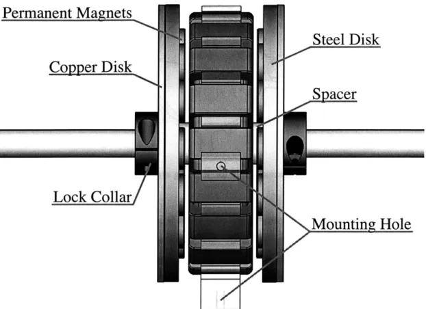
Permanent Magnets
Steel Disk
_Spacer
Cop er Disk
Lock Collar
Mountin Hole
LII'
Figure 2-4: Shaded detail view showing features of stator/rotors in the permanent magnet configuration
already be secured relative to the stator in order to hold windings in place, the utility of the ring can be extended to support the stator by securing the ring relative to the case. Figure 2-5 shows a front view of the final winding guide. The winding guide has spaces for 18 winding segments because this is a 3-phase machine, and each phase has 3 pole-pairs and thus requires 6 winding segments. The relatively complex shape of the winding guide would be tedious to conventionally make on a mill, so instead it was shaped by laser cutting. For aesthetic reasons and manufacturing speed, the guide material was chosen to be transparent acrylic. Instructions for the construction of wound stators can be found in Appendix E.
The shaft must be supported and kept it in place. With the permanent magnet machine, there can be large axial forces on the rotors if they become too close to the stator, so there must be some way of ensuring the rotors are axially stationary. The keyed rotors are secured to the shaft using shaft collars and a spacer between them. This axially links the rotors to the shaft. The shaft itself then rests on a pair of ball bearings, allowing the shaft to
0-
1
Guide Stator
Rid e SUpports
Figure 2-5: Combination guide for winding segments and stator support
easily rotate, and on the outside of the case there is a thrust bearing and a shaft collar. The outside shaft collars keep the shaft (and therefore the rotors) from moving axially, while the thrust bearing enables rotation. Theoretically only the outside shaft collar and thrust bearing on one side of the machine is needed, but for simplicity of operation, they are included on both sides since the user will probably not know without testing which side requires them. Figure 2-6 shows a detail view of the final bearing mechanism. More details
about the bearings may be found in Appendix A.
2.4
Peripherals
Several peripheral devices were designed to be used in conjunction with the machine. These peripherals enable the machine to be used in a variety of ways and a variety of experiments.
2.4.1 Torque Arm
The torque arm, shown in Figure 2-7 enables the student to measure the stall torque of the machine, or quantify the torque applied to the machine. The torque arm fastens to the shaft by a screw that compresses the "gripping fingers". A spring scale can then be attached to one of the holes along the arm. The torque arm is only intended for use while the shaft is not moving; safety concerns about a potentially rapidly rotating arm caused us to make the arm long enough to prevent a full rotation of the shaft while properly attached. Figure 2-7 shows a picture of the torque arm. A mechanical drawing may be found in Appendix A.
Thrust Bearin Ball Bearing
Lock Collar
Figure 2-6: Detail view of bearings
Urimizginug
E
2
0
0Z1
10 cm
2.5
cm
Figure 2-7: Torque Arm. Holes allow attachment of a spring scale.
2.4.2 Position Encoder
The position encoder, designed by Warit Wichakool, enables the machine user to determine the relative position, and thus velocity or acceleration, of the shaft. While a permanent magnet motor can be run open-loop, it is unstable and so the loop must be closed. Knowing the frequency of rotation is also important for other calculations, such as determining slip in an induction machine.
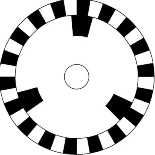
Position sensing is accomplished by an encoder wheel (Figure 2-8) attached to the shaft which which is read by an encoder board (Figure 2-9). The encoder wheel consists of
two rings of alternating white and black regions; one ring alternates every time the phase advances one winding; the other ring acts as a marker for the phase. The encoder board simply reads the brightness of the wheel and buffers the sensor signal to solid logic levels. Layouts and a part list may be found in Appendix C.1.
Figure 2-8: Encoder wheel: outer track is CLOCK, inner track is RESET
+5v 25v iCypsi d + c '5k 4+5. A38 14 8k 33k 158k3.k 5V+ U 7 Out 74HC14 k 6 k .8 lo Phctodicde/transistor 10 0k ' ?4HCk 3.3k 18047kCbypass V 15k 4+5v L4358 I >nl -D 686k 3.3k 15 - 4 . +5V I t 74HC14 U 1ek 689k , 108k Photodiode/transistr P t I k . r----3.3k
2.4.3 Motor controller
The motor controller generates a 3-phase control signal for use by the totem board from a set of square waves. The input may come from the position encoder (in the case of a permanent magnet motor) or from an onboard generator (in the case of an induction motor) and may be selected by S1. The onboard generation of square waves can be accomplished in a variety of ways. The controller shown in Figure 2-10 uses a Schmitt trigger. Board layout and a parts list can be found in Appendix C.2.
3.3k 3 - R2 10k IC5D Z5 74HCI, OND -R1 i C2 4.3k
S
VCC 74HC14 CVA 74ALSW0N R7 IC7 VC1B 2k R4 4 LM1N510 AL0NE
GND GNO11 ICC 2k GND PWM 7 4ALS0 1D IC3A J2 :1 N48~O8
OIC2A 74LSOBN 6A:r
1C2B 74LSOON N JP1 VCC Si GNO -[i To Encoder CLOCK VCTRDIV16 RSTs S5CT=0 M1 G33CT=15 14 A COUNT BCUNT [2 8 1 [41 COUN GND 74S-138N
Figure 2-10: Motor controller schematic
Figure 2-11 shows some sample waveforms generated by the controller based on input from the position encoder described in Section 2.4.2. The 74163 converts the CLOCK and !RESET signals into a binary count on the COUNT lines, with A COUNT being the least significant bit and C COUNT being the most significant. The 74LS138 then demultiplexes the COUNT signals into 6 different control lines, which are taken pairwise and put through a 74LS00 to generate the preliminary control signals. At this point, the low-side control signals are correct, but one more stage of processing is needed for the high side. As noted in Section 2.4.5, the high side control signals must not have a duty cycle of 1 for the tritotem board to function properly. In Figure 2-10, a relatively high frequency PWM signal is
generated, with the duty cycle controllable by potentiometer R5. This PWM signal is then ANDed with the preliminary high side control signals via a 74LS08 to form the final high side control signals.
Res et Clock In A Count B Count C Count Low A Low B Low C PWM High A High B High C
Figure 2-11: Example waveforms generated at various points in the motor controller
2.4.4 Drive Motor
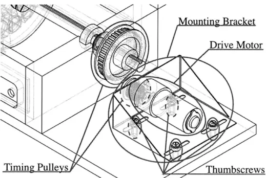
The drive motor, shown in Figure 2-12, enables the student to use the machine as a generator by providing motive power, or to control the slip rate of the induction machine. The motor is attached to the base via a mounting bracket; the motor is coupled to the shaft via timing pulleys and a timing belt. A mechanical drawing of the mounting bracket may be found in
Appendix A.
M
jutig Bracket
Drive Motor
Timing Pulleys
Thumbscrews
Figure 2-12: Detail view of drive motor peripheral. Timing belt not shown.
2.4.5 Tri-Totem Board
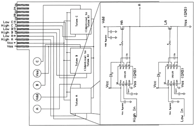
The totem board, designed by Mariano Alvira [1], enables the student to provides 3-phase power to excite the armature windings. It receives a 3-phase control signal from the finger connectors, then amplifies the signals via a IR2125 gate driver and a 40N10 NFET. The 3-phase control signal may originate from the motor controller or any other source. Note that the totem board does not have any safety interlocks on the control signals; for example, it is possible for both high and low switches in the same totem to be active at the same time, thus shorting Vdd and ground. It is up to the user to ensure such undesirable states do not occur. If correctly built, the motor controller mentioned in Section 2.4.3 ensures proper operation. Also note that the IR2125 cannot maintain a duty cycle of 1 when used as a high side gate driver; a path to ground must be present with a minimum frequency of approximately 400 Hz when the high side is active.
%C-Low C High C Low B2 High B
2
Low Am High A e VC% Its MEEMFigure 2-13: 3-phase totem controller, based on design by Mariano Alvira
2.5
Usage
This section briefly describes how to configure the teaching machine as a motor or a gener-ator and as a induction machine or a permanent magnet machine.
2.5.1 Permanent Magnet
When used as a permanent magnet machine, the rotors should be oriented such that the magnets are facing the stator. In this configuration, the copper disk serves no purpose and may be omitted if desired.
There is a large attractive force between permanent magnets and the stator; a temporary spacing material, such as cardboard, should be used when assembling the PM machine. If this spacing material is not used, the rotors will attach themselves to the stator; separation is not easy and risks damaging the armature. The insulation on the windings may be abraded, leading to reduced performance if the windings short. More detailed instructions for PM machine assembly can be found in Appendix F.
r .a E 0 43 C 0 4113 V
-I
Gi
M0 0 o c~ 0 z: 0 rr Cn 3 -4 0 I_ <r Iw U Q 012.5.2 Induction
When used as an induction machine, the rotors should be oriented such that the copper side is facing the stator. In this configuration, the magnets serve no purpose and may be omitted if desired.
The torque produced by the induction motor depends heavily on the gap between the rotor and the armature. While this should be as small as possible to maximize power transfer to the rotor, contact between rotor and armature could lead to the insulation on the windings being damaged and possibly shorting segments or phases across the rotor. Thus it is especially important to make sure the gap is large enough and the lock collars snug enough that this does not happen. More detailed instructions for induction machine assembly can be found in Appendix G.
2.5.3 Generator
When used as a generator, some prime mover must be connected to the shaft. We use the drive motor from Section 2.4.4. Assemble the the induction machine or permanent magnet machine as detailed above, then attach the large timing pulley to the right side of the shaft via the set screw. Next, loosely attach the motor bracket to the base via thumbscrews (but do not yet tighten). Figure 2-12 shows a partially connected drive motor at this stage of construction. Loop the timing belt over the two timing pulleys, then tighten the belt by
moving the motor bracket. Finally, tighten the thumbscrews.
2.5.4 Motor
When used as a motor, there must be a source of 3-phase excitation to the stator. For class experiments, the motor controller described in Section 2.4.3 and the tri-totem board described in Section 2.4.5 are used, optionally using the position encoder from Section 2.4.2 if operating as a permanent magnet motor. An alternate choice is a 3-phase generator such as the HP-6834B.
2.6
Future Improvements
There are some improvements that could be made to the machine that could be addressed for future revisions. These include additional compliance for radial walls, finished expansion
ledges, and fully symmetric rotors.
2.6.1
Radial Wall Compliance
The most important change is to include additional compliance on the radial walls. Due to imprecision in assembly of the wooden frame, the top and bottom cases do not always align, as in Figure 2-14. This misalignment causes the ball bearing to try to tilt in order to fit into the cavity, thus increasing friction on the shaft. Similarly, if the cases are misaligned in the other axes, the ball bearing may be compressed and unable to rotate freely. If the frame is misaligned, there will be resistance to closing the case. This problem has proven to be a minor one in the first run of prototype machines. Tolerances on the machining of the walls generally permits good machine operation.
Figure 2-14: Axial misalignment of the top and bottom cases
A solution that we successfully used was to expand the top cavity in both the axial and the radial dimensions, thus accepting some misalignment. If the cavity in the bottom case were expanded instead, the ball bearing would be able to shift and would not provide stable support. Other solutions which would have to be done at the time of initial construction include making the case out of a more uniform material such as metal or the addition of alignment pins.
2.6.2 Mounting Grid
Another important change is adding additional mounting holes on the base during construc-tion. Our machines were intended to have a smooth finish, with mounting holes being added as needed. While a smooth surface is visually appealing, we found it was time-consuming to add mounting holes. However, the necessary mounting holes are complete and are likely suf-ficient for foreseeable tasks. A regular hole pattern on both the expansion ledges and inside the case would be easier to add during construction; properly designed mounting brackets would then allow the use of currently unimagined devices. Note the mechanical drawing of the base in Appendix A reflects the additional holes added after initial construction.
2.6.3 Standardized Screw Size
An improvement that goes along with the mounting grid is the standardization of mounting screw size. The position encoder (Section 2.4.2) and motor bracket (Section 2.4.4) do not use the same size screws because of a lack of foresight. Redesigning one or both of these in concert with implementing a mounting grid would reduce the number of different parts necessary to use the teaching machine.
2.6.4 Fully Symmetric Rotors
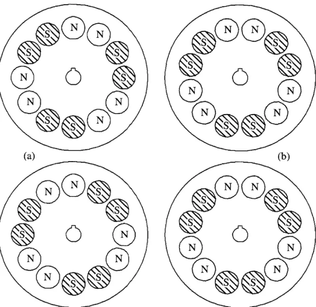
The final change we recommend regards the magnet pattern on the rotors. We intended the rotors to be symmetric to reduce the variety of parts; however, as originally designed, the rotors are not fully symmetric. Note from Figure 2-3 that the direction of the magnetic field on one side of the stator is opposite the direction of the field on the other side. Thus the magnets on the rotors should oppose each other, i.e. north opposite north and south opposite south. We might arrange the magnets for the PM machine as in the top part of Figure 2-15a. When the rotor is flipped for the other side of the stator, half of the magnets oppose their own direction and are as desired, but the other half are across from the other direction, and so the interaction of those magnets and the stator cancel instead of doing useful work. We did not discover this problem until the disks had been ordered, and so we worked around the problem by using two different patterns such that the magnets present the same pole to the corresponding magnet on the opposite disk as in Figure 2-15a. The magnet arrangement in Figure 2-15b would have enabled the use of only one type of rotor.
S
S
S
S
N
N
(a)
S
S
S
0
S
N
N
Figure 2-15: Complementary rotors: (a) asymmetric; (b): fully symmetric
(b)
Chapter 3
3-Phase Induction Machine
Electrical Description
3.1
Introduction
This chapter describes the electrical performance of the teaching machine when configured as an induction motor. An important measure of a motor's performance is the torque-speed characteristic. In order to predict this characteristic, the induction machine must be modeled. Sections 3.2 and 3.3 propose a model for the 3-phase induction machine. Section 3.4 derives model parameters from physical parameters and electromagnetic theory. Finally, the model is verified with measurements of the system and a torque-speed curve for the model is calculated in Section 3.5.
3.2
3-phase Induction Model
A high-level model of the 3-phase induction motor can be thought of as in Figure 3-1. A 3-phase source drives the stator. The stator presents a 3-phase inductor, in parallel with an ideal 3-phase transformer whose secondary links a rotor resistance. The ideal transformer is actually the interaction between the stator and the rotor via magnetic fields, the 3-phase inductor is the magnetizing inductance, and the rotor resistance is a function of slip, i.e. the difference between the shaft rotational frequency and electrical frequency.
This model should be verified with measurements of the physical machine, but a single phase of the motor cannot always be isolated when taking measurements. However, it is
Rotor -'
-3-phase source Stator Rotor Resistance
Vb(t) = Re{vote e } V(t) Re{vewte"3 }
Figure 3-1: Simple model of a 3-phase locked induction machine
sometimes convenient to analyze a single phase machine. In order to reconcile measurement with analysis, the difference between a 3-phase system and a single-phase system must be considered.
+
+ia
La
V
(t)
vs.
L
1
Lt
60 -:
Sck
Figure 3-2: Physical arrangement of a single phase inductor vs. balanced 3-phase inductors
Suppose there is a balanced Y-arrangement of inductors as in Figure 3-2 and the resulting magnetic flux in the coils during sinusoidal steady state is to be determined. The 3-phase case is similar to a single-phase case, but there is additional flux contribution from the other phases. Call these Lab for the mutual inductance of the A and B phases, and Lac for the mutual inductance of the A and C phases. Because the arrangement is balanced, by symmetry Lab = Lac. Again by symmetry, flux components not in the direction of
the flux due to phase A from phases B and C cancel. From the geometry of the setup, Lab ~ - cos(600)ILbI = - cos(600)La. By Kirchoff's current law, Ia = -(Ib+Ic). Assuming
described in terms of the current phasors (Ia, Ib, I,) and winding reactances (Xa, Xb, Xc):
Xa = wLa Xab = W Lab Xac = W Lac
and
Va = jXa - Ia + jXab - lb + jXac - Ic = jXa - Ia + jXab - (-1a)
Factoring out Ia,
Va = j(Xa - Xab) - la
Using Xab =
-Xa3
Va =j(Xa+L) a =j(3Xa)-Ia 22
So the field in a stator phase due to a 3-phase arrangement of inductors is approximately 3 that of the field due to a single-phase arrangement given equal inductors and balanced 3-phase excitation in current.
3.3
Improved Single Phase Model
A more accurate model of the machine reflects some resistance in the stator windings, Rarm, and some magnetic flux that fails to couple the stator and rotor, Lleak. When the rotor is
locked, the induction machine can be modeled as in Figure 3-3 [3].
R.a,,
Leaic
~
La|
Rrot
Figure 3-3: Improved 3-phase model for the locked induction machine
single phase of the machine, La acquires an additional factor of 1 as argued in Section 3.2.
3L
Lmag La
A single phase then looks like Figure 3-4. For clarity, the impedance can be broken down
+
R
arm
Lleak
t
_:
-a
- S
Figure 3-4: Single phase of the improved model from the viewpoint of the voltage source
into series and parallel components
Z, (jw) = Rarm + jW Lleak
ZPOW) = jwLmagRrot
jwLmag + Rrot
The impedance of the entire single phase is then
Zphase( UW) = Zs + Zp = Rarm + j(A Lleak + .jc4 Lmag Rrot
jwLmag + Rrot
The variable Rrot now and henceforth will represent the reflected rotor resistance. The following section derives expressions for each parameter based on physical dimensions of the induction machine.
3.4
Analytical Analysis
This section derives analytical expressions for the model parameters Rarm, Lmag, Rrot, and
Lleak using physical dimensions of the induction machine and electromagnetic theory. A
matlab function to evaluate the expressions for these parameters, tmot.m, is included in Appendix H.5. The derivations in this section are largely based on class notes for 6.131 [6].
3.4.1 Armature winding resistance
Ignoring skin effects (which may be important) the resistance of the armature winding Rarm is approximately the resistance of the wire. The windings on the armature vary in depth and position due to individual construction; for simplicity, we assume a uniform two layer winding throughout the armature. We define the following variables
r.
-1- __ _+I
I
4 Rwre
-.4<-Figure 3-5: Cross section of stator, showing two turns of armature winding decomposed
Figure 3-5 shows 2 turns of wire around the stator, which can be thought of a four segments of length w, four segments of length R, - Ri, and the corners. By inspection,
2 1turn = 4w
+ 4(Ro - R ) + 27rrjire + 2lr3rwire
and the total length of the windings is
1 = Na - 2 -(w + RO - Ri + r2rwire) = 120 - 2 - 5.0841 cm = 12.20 m
Rarm Resistance of armature winding, 1 a- Conductivity of copper, 5.9 -107(Q)- 1
A, Cross-sectional area of wire, 8.229 .10- 7m2
rwire Radius of wire, 5.12. 10-4 m
1 Length of armature wire winding, Nalturn
Na Number of turns per phase, 120
lturn
Length of wire per turn around the statorThe resistance of the windings is then
12.20 m
Rarm - - 0.251Q
5.9 -107 1O - 8.229 - 10-7M2
Note this underpredicts wire length (and therefore underpredicts Rarm) since inter-segment wire has been ignored. Skin effect ([4], chapter 10.7) and increased resistance due to any heating, both of which would also increase Rarm, have also been ignored.
3.4.2 Distributed Winding
We will briefly consider the impact of distributed windings. The following sections assume that winding segments consist of a single wire loop; in reality, winding segments are com-posed of about 20 loops which are spread out over some non-negligable distance. This has the effect of "smearing out" the field. The ratio between the 1-conductor case and reality is called the winding factor, k,.
0 Magnetic field ..---.-Wire
T
ifff
Stator ... Sum of field contributions 0/2Figure 3-6: Progression from single wire to distributed winding
Figure 3-6 shows the progression from a single wire to distributed winding. The total
current in each stage remains constant. For simplicity, only the fundamental of the magnetic field is considered. The vectors in the top row represent the contribution of each wire to the sinusoidal magnetic field, the bottom row shows the sum of the contributions. In the limit of an infinite number of wires, the winding factor is the ratio of the chord length to the arc length. The chord length is 2r sin(u), the arc length is r6O, and so the winding
factor is s" )
2
2nt
O=
27c/6
Figure 3-7: Electrical winding angle
As Figure 3-7 shows, the magnetic field due to the armature windings does a complete N-S-N (27r) pattern over 2 segments of the same phase. In between are 4 other winding segments from the other phases, so a single winding segment occupies an electrical angle of 3.. 7r 0, = electrical angle = -3 so sin(-)
km = winding factor for distributed winding = 2 0.954
2
Note this winding factor is for the limit case -i.e., there are an infinite number of wires. This is an approximation, so the true winding factor is in fact somewhere between 0.954 and 1.
3.4.3 Magnetizing Inductance
While some of the electrical power input to the stator is lost in the armature windings due to wire resistance, a (hopefully) larger amount will couple to the rotors and be converted to mechanical force. The force coupling the stator and rotor is due to the interaction of the time-varying magnetic field with the rotors;these distributed fields are represented in a lumped model called magnetizing inductance, or Lmag. This subsection assumes that only the axial sides of the stator couple to the rotors, and that on these sides there is no flux loss due to leakage or end effects.
convenient term derived from various parameters of the inductor which are usually constant, and so are lumped together. A magnetic flux 4D links the elements of the magnetic circuit in the machine:
A(area)
N turns
Ur
(permeability)
Figure 3-8: Typical solenoid
Li = A = N4)= total flux linkage of inductor
L Inductance
i Current through inductor
(D Magnetic flux through inductor, pop,HA
Po permeability of free space, 47r .10-7 Hy/m
Pr relative permeability of core
Hx magnetic field
A Cross-sectional area encompassed by inductor
A value for Lmag can be determined given an expression for the magnetic flux through the inductor, 4. Figure 3-9 shows a simplified sketch of the rotor and stator. For simplicity, instead of being a ring and disc, it is shown flattened into a bar and plate. Additionally, the single coil represents N turns. For now, only one winding segment will be considered, so
Na _total turns in a single phase N = number of turns in a single phase segment = N nur of sgents
~p
number of segments Figure 3-9 shows only part of a single winding phase, and does not show the second rotor; everything is applicable to the second rotor by symmetry. Assuming flux remains in the x-y plane, 4) = A = 5y due to continuity across the indicated control volume and symmetry./
)
I
111)
Figure 3-9: Simplified cross-sectional sketch of magnetic field
Consider Ampere's law around the path indicated in Figure 3-10. The magnetic flux density
/
/
Rotor
Stator
U
Figure 3-10: Simplified cross-sectional sketch of rotor and stator
in the rotor and stator is presumably very small compared to the flux density in the air, so the only contribution to the path integral comes from the two segments of the path in air.
H - dl = 2g|Hy| = Ni Rot. I-A / A 1,F IF IF IF
'Stator
N
N
'%
vp 11 NJ
11 IN 11
X
Ly No X I 1 119 T T T T t T T T T T Q9 I
Rearranging, the magnitude of the axial field is then
J~j-Ni 2g
Note that the air gap given is expected to vary widely between motors, and even between
different assemblies of the same motor. A typical value would be 0.9 cm, which is the
air gap from the measurements in Section 3.5. Since segments of a phase are wound in opposite directions, the direction of the magnetic field in the stator alternates and therefore pushes outward between phase segments as in Figure 2-3. Since the phase segments have some width, the winding correction factor k, as described in the previous section must be included. Only the fundamental of the field is considered, so the magnitude increases by A. Returning to the case of a toroidal stator, the field is sinusoidal in 0 with period 2r . The fundamental of this field is then
Ni 4
Hy = 4k, sin(pO)
2g 7r
Figure 3-11 shows two views of the same flattened, simplified rotor and stator. The dashed line (2D view) and grey region (3D view) represent the same area of interest. Integrating the magnetic field over this area yields the magnetic flux, 4Y. For the corresponding case for the un-flattened rotor and stator, the outer integration and substitution of Hy, yields
D -k 0 Ro 2 - R.2 P Ni 4
Y =k
J
poHyjr - dr -d= kj 2o 2g7ksin(pO)d6fo Ri fo i k
Pulling out constants and carrying out the remaining integral then gives
4 Nk2 i(R02 - R 2) . 4 Nkw2i(R2 - R 2) 2
4
y = -O s4g)d -1p0
7r 4g l 7r 4g p
This is the flux due to a single loop of wire, but the model is in terms of the inductance of an entire phase. Flux was assumed to remain in the x-y plane, so 4D, and 4 y. A factor of two must be introduced because the symmetric second rotor side has thus far been neglected. The flux due to a single phase segment containing N turns is then
4 N2k 2
i(R02 - R 2) 4 N2k 2i(R02 - R 2)
2N4 x = A = 2N y = 2-p10 = 2-p02
2D View
J/7 /~_ _~ R otor
-
/
I7/,(7/
3D View
Figure 3-11: Sketch of flattened, simplified rotor and stator, part of one phase
Remembering that N = E, the inductance due to a single phase is then
A 4 Na2kw2 (Ro2
Ri2
)
L= 2
p-
= -po 22
Finally, to compute Lmag from LI, there is a factor of
j
following the argument in Sec-tion 3.2. The magnetizing inductance in the single-phase machine model corresponding to the 3-phase machine operating in balanced conditions is3 34 Na2kw2
(Ro2 - R,2
) Lmag = -22 *-- 2
Lmag is then approximately
3 4 _7 Hy 1202 -0.9542 . (0.0539752 - 0.031752)m2 = 3.855.10- Hy
2 7r m 2- 0.008636m -32
This expression is expected to be higher than reality because all flux was assumed to remain in the x-y plane and all flux was assumed to cross the air gap.
3.4.4 Leakage Inductance
The magnetic field due to the stator currents does not completely couple with the rotors; some of the magnetic fields link only the stator or only the rotor. These distributed fields are represented by the lumped model leakage inductance Lieak. This subsection assumes that the radial faces of the stator are the only components that are of interest in terms of leakage. Fields from the axial faces are ignored because they were previously assumed to completely couple with the rotors. End effects are also ignored, i.e. the fields are treated as if they were generated by a wire of infinite length. Figure 3-12 shows the coordinate system used for this subsection, while Figure 3-13 shows the important dimensions. We define the following variables
RWO Outer radius of windings Ro + 4Rwire
Rw Inner radius of windings Ro - 4Rwire
Rs Shaft radius 0.635 cm
Figure 3-12: Sketch of flattened coordinate system of interest, only currents on top face are shown
noesfo 668 [].Sicet e mer of the ein m e i ifrntebudr
*Stator
Themagnetice ae can 3 alobeitensos interst ofe vae poeilA.epee as .
The mageti fil srltdtocreti h wnig y pr'sla.
V* xF B =4
Temgeifilcaalobwrteintrothvecto pei al A.
Substituting,
V x (V x A) = poJ= V(V -A) - V2A
Using the Coulomb gage
V-A=0
then
V2 A = -poJ
Assuming that current only flows in the y-direction, this becomes 1 8 BA1 a2
(rA + r2 02 Ay = -po J
Assuming AY and J, both have angular dependence eiP0, i.e. vary sinusoidally,
10
(
0A,\ p2I r ) r2AY = -PO J
r Or Or) r2AY JY
and the general solution for the vector potential is
AY = A+rP + A-r-P - Po0Jr2
4 - p The regions of interest are
0 RWO < r < oo
wo Ro r < Rwo
wi Rwi r < Ri c Rshaft r < Rwi
Note that region "o" interacts only with region "wo"; similarly, region "wi" interacts only with region "c". Also note the constants A+ and A_ are different for each region. Finally note there is no current in regions "o" or "c", so in those regions the solution for the vector potential is just
AY = A+rP + Ar~P
From B = V x A,
1 0A
and
OA~ B0 =- Or
ar
First consider the outer regions, which compose the vector potential AY0. As r -+
oo,
BO -+ 0 since from very far away, the stator looks like a point. Therefore
lim BO = 0 = lim -pA o+rP1 + pAO-r-P-1
r-*oo r-.oo
which implies Ao+ = 0. Another boundary condition is that at r = R, BO 0, so
-pAwo+RoP~ 1 + pAwo-Ro-P-1 + 2poJRo= 0
4 - p2
Solving this for AwO+ in terms of Awo_,
A = Aw0 R- 2 + 21oJy Ro-p+2
p(4 - p2
)
The circumferential component of the magnetic field, BO, must be continuous at r Rw0 .
This implies
+~P-1+ oJRWo = -- +pAo -P-1
Substituting~ p~wo- in4 A - is then - p2
Substituting in for Awo+, A,_ is then
Ao_ = Awo (1 - ROo2
)
RWO- 2 - _2 )Rup+2 RoP-2)w + 21 " (I p(4 - p2)The final boundary condition is that Br must also be continuous, even at r = Rw,. This
implies
Awo+RwoP + AwoRwo-P- 1 - yoJyR2"' = Ao+RwOP- 1 + AoRwo-P~1 = AoRwo-P-1
4 - p2
Substituting in for Awo+ and A_,
A = (1 p(4 - p2)