READ THESE TERMS AND CONDITIONS CAREFULLY BEFORE USING THIS WEBSITE. https://nrc-publications.canada.ca/eng/copyright
Vous avez des questions? Nous pouvons vous aider. Pour communiquer directement avec un auteur, consultez la
première page de la revue dans laquelle son article a été publié afin de trouver ses coordonnées. Si vous n’arrivez pas à les repérer, communiquez avec nous à [email protected].
Questions? Contact the NRC Publications Archive team at
[email protected]. If you wish to email the authors directly, please see the first page of the publication for their contact information.
NRC Publications Archive
Archives des publications du CNRC
This publication could be one of several versions: author’s original, accepted manuscript or the publisher’s version. / La version de cette publication peut être l’une des suivantes : la version prépublication de l’auteur, la version acceptée du manuscrit ou la version de l’éditeur.
Access and use of this website and the material on it are subject to the Terms and Conditions set forth at
An Evaluation guide for performance assessment of air barrier systems Brown, W. C.; Lawton, M.; Poirier, G. F.; Di Lenardo, B.
https://publications-cnrc.canada.ca/fra/droits
L’accès à ce site Web et l’utilisation de son contenu sont assujettis aux conditions présentées dans le site LISEZ CES CONDITIONS ATTENTIVEMENT AVANT D’UTILISER CE SITE WEB.
NRC Publications Record / Notice d'Archives des publications de CNRC:
https://nrc-publications.canada.ca/eng/view/object/?id=f5ff38ea-935f-49aa-aa37-bf251e5f37c5 https://publications-cnrc.canada.ca/fra/voir/objet/?id=f5ff38ea-935f-49aa-aa37-bf251e5f37c5
An Evaluation guide for performance assessment of air barrier systems
Brown, M.C., Poirier, G.F.; Lawton, M.; Di Lenardo, B.
NRCC-47670
A version of this document is published in / Une version de ce document se trouve dans: Conference on Thermal Performance of the Exterior Envelopes of Buildings VII,
Dec. 6-10, 1998, Clearwater Beach, Florida, pp. 773-780
An Evaluation Guide for Performance Assessment of Air Barrier Systems
W.C. Brown
Building Envelope and Structure Program Institute for Research in Construction National Research Council of Canada
G.F. Poirier
Canadian Construction Materials Centre Institute for Research in Construction National Research Council of Canada Mark Lawton
Morrison Hershfield Ottawa, Canada
B. Di Lenardo
Canadian Construction Materials Centre Institute for Research in Construction National Research Council of Canada
Abstract: The National Building Code of Canada (NBC) requires that an ‘effective’ air barrier system be incorporated within the building envelope. Although the NBC addresses the
performance characteristics to be considered to demonstrate that an effective air barrier system has been achieved the NBC does not prescribe any specific test protocols with acceptance criteria to verify compliance of proprietary air barrier systems. This paper outlines the developmental aspects of producing an Evaluation Guide for use by the Canadian
Construction Materials Centre (CCMC) for the evaluation of proprietary air barrier systems. The development of the protocol and the acceptance criteria focus on the five main features of any air barrier system, specifically an air barrier system must: i) have an acceptable air leakage rate, ii) be continuous throughout the building envelope, iii) withstand structural wind
loading expected during its service life, iv) be durable and v) be buildable or reproducible in the field.
Introduction
The National Building Code of Canada (NBC) contains requirements for air barrier systems that reflect industry’s knowledge, experience and practice. Important changes in the air barrier system requirements have been incorporated into the 1995 NBC to correspond to the evolution of thought since the previous edition. The NBC is acknowledging that air
movement is a dominant factor in the transport of moisture through building envelope assemblies. It is also an important component of heat transfer and as a result, the importance of an air barrier system is also reflected in the Model National Energy Code of Canada for Buildings. Many problems concerning inadequate building envelope performance and deterioration can be attributed to inadequate or failed air barrier systems. This can also be attributed to the fact that no specific test protocols with acceptance criteria was available to verify compliance of air barrier systems.
There was a definite need to develop a process to validate air barrier systems for the marketplace in a fashion akin to window testing. The protocol for validation had to be a universal performance-based approach for evaluating an air barrier system. The NBC
Committee expressed a need for a document that could be referenced to verify compliance to the Code and, at the same time, proponents of proprietary air barrier systems were seeking evaluation by the Canadian Construction Materials Centre (CCMC), Canada’s national evaluation service, to demonstrate compliance to the Code. This led to the development of CCMC’s Evaluation Guide for the assessment of air barrier systems.
NBC Air Barrier System Requirements
Background
The NBC performance requirements are greatly based on research that was initiated some 30 years ago by Neil Hutcheon1 who listed the principal requirements of an exterior wall. From that initiative it is now known that the air barrier system is fundamental to the requirements concerning the control of air, heat and water vapour flows. It also plays an important role in the control of rain penetration and external noise transmission.
To meet these requirements, the air barrier system of an exterior wall must be: • constructed of materials that are adequately airtight;
• continuous through the building envelope;
• strong enough to resist the air pressure loads imposed on it, transfer these loads to the building structure and have enough rigidity or support so that deflection under load is accommodated in the specific wall design;
• durable enough to provide the necessary performance in the service environment anticipated;
• buildable.
1 Hutcheon, N.B., Requirements for Exterior Walls. Canadian Building Digest (CBD) 48, Division of Building Research, national Research Council, Ottawa, 1963.
Material Requirements
Consistent with the first principal requirements listed above, the NBC specifies that the ‘material’ that provides the principal resistance to air leakage within the air barrier system is required to have an average leakage characteristic not greater than 0.02 L/(s•m2) at 75 Pascals (Pa) pressure difference. (This represents the leakage rate, for example, through a 12.7-mm sheet of unpainted gypsum wallboard.) This air leakage rate at 75 Pa is not intended to represent typical leakage of the material in situ, since pressure differences across the building envelope are often much higher than 75 Pa. This reference pressure difference of 75 Pa is merely used to characterize a material property. The NBC allows materials of lower airtightness , i.e., leakage
greater than 0.02 L/(s•m2), if it can be shown that this will not have adverse effects on the health or safety of the users of the building. Again, consistent with the principal requirements the NBC specifies that the air barrier system must also be continuous across construction joints, control and expansion joints, at penetrations through an assembly, and at junctions with other assemblies.
System Requirements
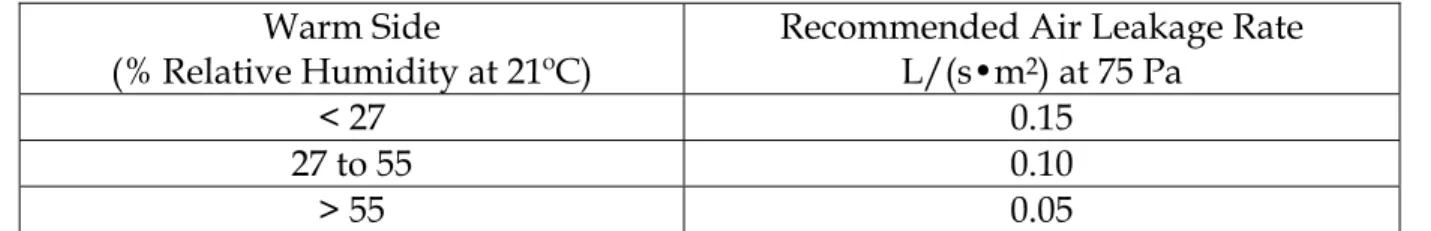
However, the code committee responsible for air barrier system requirements recognized that, ideally, the maximum air leakage rate of the air barrier system (including materials and joints) should be specified. At the time of the writing of the 1995 NBC this was not viewed as a practical approach because there are relatively few published data about leakage of the air barrier system as a whole and there was an absence of a standard evaluation protocol. To assist designers, the Appendix to the NBC provides a list of recommended maximum air leakage rates suitable for most climates in Canada (Table 1 below). These air leakage rates were first suggested in the Institute for Research in Construction (IRC) Building Science Insight 86, “An Air Barrier for the Building Envelope.” They were based on the perceived need to provide higher levels of airtightness than required at the time by the current American Architectural Manufacturers Association (AAMA) for metal & glass curtain walls.. Measured tightness of assemblies performing well at the corresponding humidities has since supported the validity of the recommended rates listed in Table 1.
Table 1. Previously recommended maximum system air leakage rates. Warm Side
(% Relative Humidity at 21ºC)
Recommended Air Leakage Rate L/(s•m2) at 75 Pa
< 27 0.15
27 to 55 0.10
> 55 0.05
This system air leakage rate is the leakage through the opaque insulated portion of the envelope and is not to be confused with the overall air leakage rate of a building as is measured by whole-building air leakage tests. These air leakage rates do not take into
consideration the location of the air barrier system within the wall assembly, its water vapour permeance or the water vapour permeance of materials outboard of the system.
Evaluation Guide for Performance Assessment of Air Barrier Systems
Objective
In the development the Evaluation Guide for air barrier systems a research team was charged to identify the necessary test procedures, protocols and to determine acceptance criteria. First, the air leakage rates that were previously published as proposed values (i.e. Table 1) had to be verified for various locations in Canada and for various wall configurations. The wall
the wall assembly, varying the properties of the air barrier material and varying the properties of other components within the wall system.
Once permissible air leakage rates would be set as the definitive criteria, a consistent approach for the measurement of the air leakage rate of air barrier systems had to be formalized in a test procedure. This test procedure would be used to establish the air leakage ‘rating’ of the
system at the standard reference pressure of 75 Pa.
For structural assessment, the air barrier system would have to resist the wind loads that it may be exposed to during its service life. A research team needed to characterize the anticipated wind loads within a test procedure and deflection measurements were also necessary as prescribed by the NBC.
Once an air barrier system was deemed acceptable, by surviving the prescribed structural wind loading and maintaining an acceptable air leakage rating, it had to be confirmed that the materials of the system were durable. A protocol had to be established to account for UV degradation during construction and aging mechanisms that occur within the wall assembly during the life of the building. The air barrier system components and accessories had to maintain their strength properties as well as the air permeance properties.
Finally, since the air barrier system is a site-built system it had to be buildable in the field, it was determined that the test specimens had to be representative of the field situation. The test specimens would have to be constructed in accordance with the field delivery system intended by the proponent of the system. Air barrier systems that would be sold as ‘commodity-type’ components to be erected by any third-party would have test specimens constructed by a third-party with no prior knowledge of the system. While systems conceived and developed to be delivered by trained and licensed installers would have these trained personnel
construction the specimen. This approach was intended to capture as much system variability as possible within a laboratory environment.
To accomplish the task of developing this Evaluation Guide, CCMC relied on a network of experts within the Institute for Research in Construction that had a demonstrated expertise in this field of evaluation. The research team involved experts in heat and mass transfer and computer modeling. Experts in structural wind loading to produce a wind-loading schedule that would be representative of the Canadian climate, as well as, polymer chemists to help assess the durability of the materials proposed as components of the air barrier system.
Permissible Air Leakage Rates
It is now generally accepted that the leakage of moist, heated interior air into cold spaces of building envelope assemblies is a far more significant cause of problems resulting from condensation than the diffusion of water vapour. The most important function of a wall air barrier system is to control the flow of air into and through a wall, so that:
• drying is rapid enough to avoid the deterioration of materials or the growth of molds and fungi, which are not only health concerns but also agents of deterioration.
Determining the relationship between air leakage and moisture accumulation requires complex mathematical analysis. One of the key research projects carried out during the development of the Evaluation Guide investigated this relationship by computer simulation. A study was carried out by IRC and the Technical Research Centre (VTT) in Finland, using a jointly developed computer model, to evaluate the effect of various parameters (air leakage, water vapour permeability, weather, insulation levels, and location) on the amount of condensation that is likely to occur inside a typical wood-frame wall assembly.
In deciding what modelling assumptions it should work with, the project team relied on previous research findings to define common construction features that would make a wall system more susceptible to condensation. These features included the following:
• The wall would be well insulated. High insulation levels keep the outer portions of the wall cooler.
• The most airtight surface would be at the outer sheathing layer. (This situation could easily occur when low-permeability sheathings are used in conjunction with penetrations of the interior sheathing or when the air barrier system is located on the cold side.)
• The entry of exfiltrating air into a particular wall cavity would be at a single leakage point. • The wall would operate under a slight exfiltrating pressure. (This pressure is commonly
created by stack forces or mechanical ventilation. In addition, there are exfiltrating and infiltrating pressures that are created by wind.)
The composition of the simulated stud cavity is illustrated in Figure 1. An air barrier system is located on the exterior of the assembly. Air leakage is simulated through a hole such as an electrical outlet in the interior finish. Air leakage through this single hole then exfiltrates through the exterior air barrier system in a uniformly distributed fashion. The climates of Edmonton, Halifax and Ottawa were simulated for temperature, wind pressure, wind
direction, and vapour pressure while a positive baseline air-pressure difference of 10 Pa was simulated across the wall.
The mathematical modelling included the following:
• temperature • air pressure
• water vapour pressure • thermal insulation
• leakage rate of air barrier system
• water vapour permeance of air barrier system • added insulation outside air barrier system
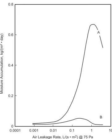
• water vapour permeance of the vapour barrier Figure 1. Mathematical modelling of moisture accumulation in a stud cavity The modelling of the relationship between air leakage rates and moisture accumulation showed the complexity of the hygrothermal mechanism. Curve A in Figure 2 shows how moisture accumulation varies with leakage rate for one set of assumptions related to temperatures, humidity, insulation, and air barrier permeability. Note how moisture
accumulation increases with leakage up to a certain point and then decreases as the increased heat from the leaking air warms the interior surfaces to a temperature above condensing. Very airtight or very leaky walls will not have a problem, whereas one with an intermediate level of airtightness may. The location of the crest for this moisture accumulation varies with the assumed temperature, humidity and insulation level. The accumulation rate and location of the “hump” changes dramatically, for example, if the air barrier is kept warmer by placing some insulation outside the air barrier. Curve B in Figure 2 shows the effect of adding
insulation with a thermal resistance of 0.75 K•m2•W-1 (R4.3) outside the air barrier modelled in Curve A.
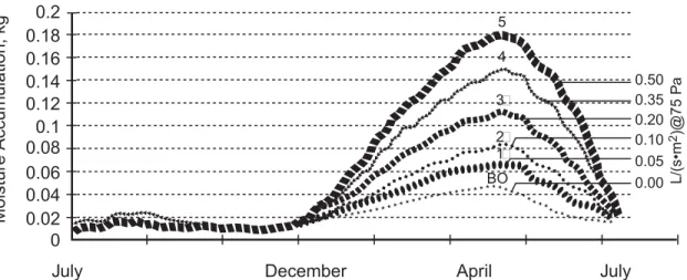
The simulation also indicated whether water would condense and be retained until the arrival of warm periods of the year, when mold and fungi are likely to grow. Figure 3 shows an example of a yearly moisture collection curve from the study. The largest accumulation of moisture occurred when:
• the air barrier system was outside the insulation,
• the assembly outside the insulation had a low water vapour permeance, and • the indoor relative humidity level was high.
Figure 3. Total mass of moisture in the exterior 15 mm of insulation at the condensing surface with different air permeances of the air barrier layer and 60 ng/(Pa•s•m2) vapour permeance. For more information on the modelling conducted, see “Effect of
Exfiltration on the Hygrothermal Behaviour of a Residential Wall Assembly,” Tuomo Ojanen (VTT) & Kumar Kumaran (NRC), Journal of Thermal Insulation and Building Envelopes, Volume 19, January 1996.
Small differences were noted in moisture accumulation for the buildings modelled in the three cities at the end of the one-year cycle. The Halifax simulation indicated only a slightly lower moisture accumulation than that of Edmonton. This stems from the fact that, although the Edmonton winter is colder than that in Halifax, the drying potential to reduce cavity moisture is more limited in the Maritimes than in the Prairies.
Even if the arrangement of materials is such that air leakage does not result in moisture
accumulation, a maximum air leakage rate for air barrier systems should be defined to control energy flow through the wall. The study showed that at an air leakage rate of 0.2 L/(s•m2) at 75 Pa, the heat loss due to air leakage was approximately 15 percent of the conductive heat transfer through a simulated RSI 3.6 (R20) wall system. This rate of heat loss was accepted to be commensurate with the maximum allowable air leakage rate. The CCMC evaluation criteria
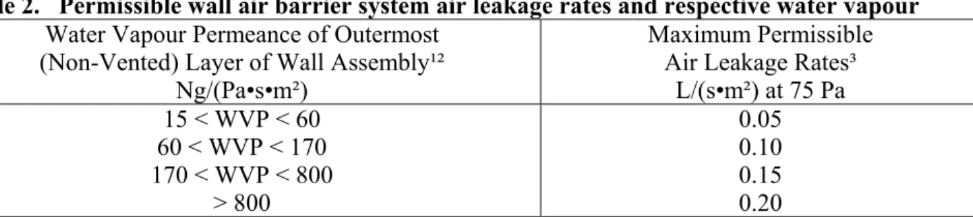
consider both moisture collection potential and energy conservation to define the maximum allowable air leakage rate. Modelling with an external air barrier system and typical indoor humidity levels of up to 35 percent at 21°C resulted in the maximum system air leakage rates shown in Table 2.
Table 2. Permissible wall air barrier system air leakage rates and respective water vapour
Water Vapour Permeance of Outermost (Non-Vented) Layer of Wall Assembly¹²
Ng/(Pa•s•m²)
Maximum Permissible Air Leakage Rates³
L/(s•m²) at 75 Pa 15 < WVP < 60 60 < WVP < 170 170 < WVP < 800 > 800 0.05 0.10 0.15 0.20 Notes:
1. For an air barrier system installed on the cold side, adjacent to a vented space, this value would be the WVP of the most water vapour impermeable material of the air barrier system. For air barrier systems located within the wall assembly (i.e., toward the warm side within the insulation), this value would apply to the material with the lowest WVP outboard of the air barrier system and inboard of any vented space.
2. The CCMC evaluation report will state that where the designated air barrier system is located within the wall assembly there must be no material installed outboard of the air barrier system that has a lower WVP for the respective air leakage rating.
3. The maximum permissible air leakage rate for an air barrier system within any of the first three categories of WVP ranges may be increased by 0.05 L/(s•m²) at 75 Pa, to a maximum of 0.2 L (s•m²) at 75 Pa, if the air barrier system is insulated in accordance with Table 3 for the respective geographical locations. The maximum permissible air leakage rate of 0.2 l/(s•m²) at 75 Pa is cut-off point based on acceptable heat loss into the wall assembly.
4. For proponents of an air barrier system in buildings operating at relative humidities greater than 35%, CCMC will establish the permissible air leakage rate case by case.
The assessment of the maximum air leakage rate is based on total system leakage, including anticipated joints, connections and penetrations. Table 2, developed for the Evaluation Guide, lists the maximum allowable leakage rates for a building with indoor relative humidity levels up to 35% at 21°C. Note that the allowable leakage depends on the water vapour permeance (WVP) of the outermost (non-vented) layer of the wall assembly.
As indicated in the notes to Table 2, where insulation has been placed outside the air barrier system, a higher air leakage rate is possible without condensation. The CCMC evaluation criteria increase the allowable air leakage rate by 0.05 L/(s•m2) at 75 Pa when the ratio of the insulation value of the wall outside the inner surface of the air barrier system is adequate. This ratio varies with geographic location. The permissible air leakage rates were developed based
on the wall assembly having a vapour barrier of at least 60 ng/(Pa•s•m2) on the warm side of the insulation.
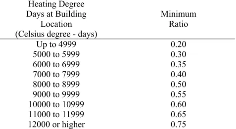
Table 3. Ratio of outboard to inboard thermal resistance*
Heating Degree Days at Building
Location (Celsius degree - days)
Minimum Ratio Up to 4999 5000 to 5999 6000 to 6999 7000 to 7999 8000 to 8999 9000 to 9999 10000 to 10999 11000 to 11999 12000 or higher 0.20 0.30 0.35 0.40 0.50 0.55 0.60 0.65 0.75
*Note: The ratio is the total thermal resistance outboard of a
material’s inner surface to the total thermal resistance inboard of the material’s inner surface.
Air Leakage Test Procedure
The air leakage rates reported for full-scale test assemblies under the evaluation procedure are not merely those rates recorded during a single test at 75-Pa pressure difference. A particular test sequence is specified for three test specimens. The air leakage tests are conducted over a spectrum of loadings up to 500 Pa. Air leakage data derived from the opaque wall tests (see Figure 4), conducted after structural loading tests as discussed below, are then shown in a graph plotting air leakage versus pressure, and the value at 75 Pa is only accepted if the air barrier assembly has also provided good performance at higher pressures. This means that during the tests the air leakage rate of the specimen would perform linearly across the range of pressures. This is established by the testing agency using standard mathematical data fitting procedures. In addition, the air leakage of those test specimens with penetrations through or connections to other elements (see Figures 5 and 6) must not exceed the air leakage of the opaque wall by more than 10 percent. Thus, appropriate air leakage behaviour for all three specimens with no more than 10% variability constitutes the CCMC acceptance criteria if the air leakage rate falls within the permissible rates of Table 2.
In addition, as air barrier systems are site-built systems, specimens 4 to 6 must be constructed in a fashion that is representative of how they will be constructed in the field. Proponents of a proprietary air barriers system intending to specify certified installers may have their
specimens constructed by said certified installers. While proponents of a system that is marketed as a ‘commodity-type’ system to be constructed by any third-party shall have their
specimens fabricated by a third-party with no special knowledge of the system. Thus
attempting to capture the variability that may occur as part of the delivery system to the field.
Figure 4. Opaque wall specimen used to obtain base air leakage data.
Figure 5. Test specimen(s) with penetrations through the air barrier system.
(Note: window, duct, outlets and pipe are sealed, only interface with penetrations and opaque portion of factor into the air leakage measurement)
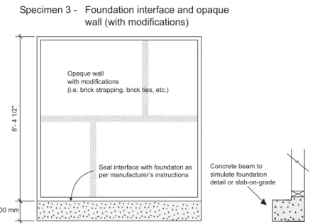
Figure 6. Test specimen(s) with connections to other elements through air barrier system.
Structural Capacity
The structural capacity of the air barrier system is determined by using procedures that test the air barrier system to the design wind pressure experienced by low-rise wall systems in most climates in Canada. In addition, the deflection at 150 percent of the wind pressure is measured and reported because the information is important to designers.
A wall system is subjected to lateral air pressure loads created by stack forces, mechanical forces, and wind. Stack forces and mechanical forces can be characterized as being relatively low in magnitude but long in duration; whereas wind forces, and particularly those associated with gusts, may be temporary but are much higher in magnitude.
Because the air barrier system is by definition the most airtight plane in the wall, it will carry most of the air pressure loads. The designer has to assume that the air barrier system must be able to resist and transfer the full wind pressure to the building structure without damage to the air barrier system or other components of the wall system.
Structural Loading Requirements
To evaluate the structural capacity of the air barrier system specimens in relation to expected wind loads, the specimens are tested for sustained, cyclic and gust loadings. The pressures for these tests shown in Table 4 are established in accordance with the 1-in-10-year return wind pressure for the geographical area in which the wall will be situated. These design load levels are consistent with wind loading for the structural design of glass for windows in the NBC, since windows are part of the air barrier system for the building. The 1-in-10-year return wind
was also considered more appropriate when considering the specified wind loads on a
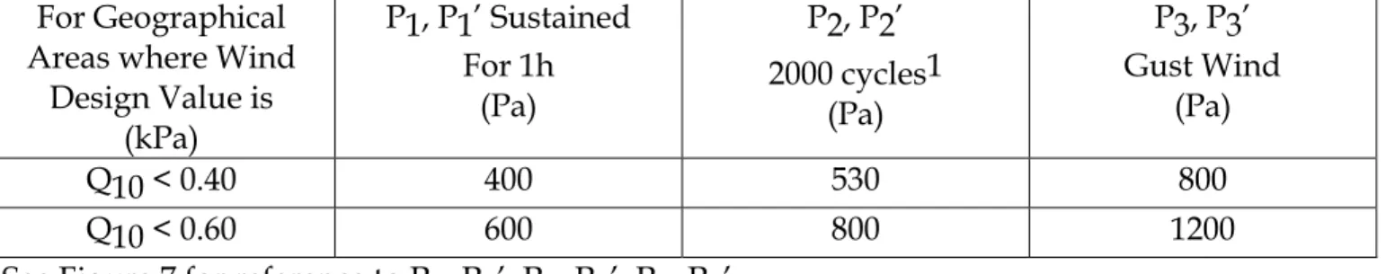
building as per the structural requirements of Part 4 of the NBC. The 1-in-10-year return wind is specified for cladding with a gust factor of 2.5 while the design of structural members is based on the 1-in-30-year return wind with a gust factor of 2.0. Since the air barrier system is within the wall assembly it was rationalized that it should be subjected to the wind design value of the cladding with a gust factor representative of what the structure may experience. Table 4. Wind pressures established in accordance with the 1-in-10 year return wind load for the geographical area
For Geographical Areas where Wind
Design Value is (kPa) P1, P1’ Sustained For 1h (Pa) P2, P2’ 2000 cycles1 (Pa) P3, P3’ Gust Wind (Pa) Q10 < 0.40 400 530 800 Q10 < 0.60 600 800 1200
See Figure 7 for reference to P1, P1’, P2, P2’, P3, P3’.
1The 2000 cyclic loads could be applied in four stages of 500 cycles, reversing from positive to negative pressures; or in two stages of 1000 cycles, reversing from positive to negative.
The wind loads are applied according to Figure 7 and the test pressures and cycles are thought to be representative of the wind pressures and fatigue on the air barrier associated with two or three major storms which any building would likely experience during a 10-year period.
Figure 7. Structural (wind) loading schedule
The material providing the principal plane of airtightness of the air barrier system need not rely on its own strength to resist these structural loads. A flexible membrane can be supported by another material or a framing system that is more air permeable but has the necessary structural strength and rigidity. Any proprietary air barrier system must identify both the plane of airtightness component and its structural components, such as substrates and fastenings, which are part of the ‘system.’
Deflection Requirements
Deflection of the air barrier system is measured at the loads shown in Table 5 and are considered important because deflection of the air barrier system under load can: • place wind loads on surfaces that were not designed to support them,
• displace other materials in the wall system, and
• result in tension loads in the membrane (or joints) and affect its long-term service life.
The wall design must accommodate the deflection of the air barrier under full load and it must also allow some margin for construction tolerance. The CCMC evaluation criteria and Part 5 of the NBC are based on the premise that the design should accommodate the degree of air barrier system deflection that would occur if 1.5 times the design wind load were placed on it. With the CCMC evaluation procedure, this level of deflection is measured and reported.
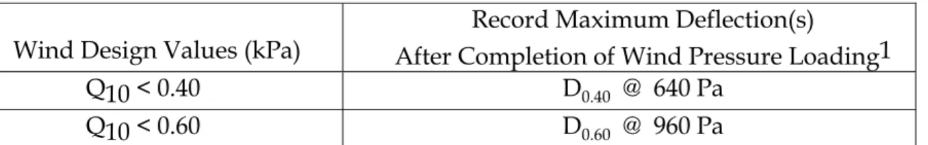
Table 5. Deflection of the air barrier system at specified loads
Wind Design Values (kPa)
Record Maximum Deflection(s)
After Completion of Wind Pressure Loading1 Q10 < 0.40 D0.40 @ 640 Pa
Q10 < 0.60 D0.60 @ 960 Pa
1 The wind pressure loading shall be maintained for a minimum of 10s and the maximum deflection, at any point on the specimen, from the supporting member of the air barrier system shall be determined for both positive and negative pressures. The loadings are 1.6 times Q10 from adjustments for exposure in urban areas.
It should be noted that with a flexible membrane supported on a framing system the ability to resist lateral loads depends on the ability of the membrane and joints to resist tensile forces. This requires that joints in the membrane and to adjacent construction be detailed to provide the required strength. This is usually done by clamping the joints between rigid members.
Air barrier system rigidity also affects the performance of rainscreen walls. If the air barrier deflects, it allows more of the dynamic pressure load to be borne by the exterior cladding. This can increase the level of rain penetration
Continuity of the Air Barrier System
The continuity within the air barrier system is addressed by requiring testing of specimens that contain fasteners, joints and connectors to adjacent construction as shown in Figures 4 to 6. It is also addressed by determining the air leakage rate of the specimens after they been exposed to the structural loading test. The air leakage test results on these specimens after structural loading must not vary by more than 10 percent from the opaque wall system air barrier to meet the requirements for continuity.
The test specimens have to be constructed in accordance with the field delivery system intended by the proponent of the system. Air barrier systems that would be sold as
‘commodity-type’ components to be erected by any third-party would have test specimens constructed by a third-party with no prior knowledge of the system. While systems conceived and developed to be delivered by trained and licensed installers would have these trained personnel construct the specimen.
The continuity within the air barrier system is also addressed by the requirement of an installation manual with detailed drawings. The construction process, the material
requirements and how the continuity of the plane of airtightness is maintained within the system must be clearly identified in the manual. The installation requirements must also be coupled with the identification of a quality assurance plan.
Durability
Durability can be defined as the ability of a building component to perform its required functions over a period of time in the environment to which it is exposed.
The durability of an air barrier system depends on compatibility with adjacent materials and the loads to which it is subjected over its service life. The factors in the local environment that can play a role include temperature, moisture, solar radiation, electrochemical factors, and biologically active material. The required durability of any material or system depends on how long it is intended to perform and whether it can be maintained or economically repaired. Some air barrier systems are accessible for maintenance, but many are not because they are incorporated within the wall construction. The NBC implies that inaccessible air barrier systems be considerably more durable than accessible and repairable ones.
The Evaluation Guide has defined durability criteria based on the accessibility of the air barrier system and the specific materials used. Currently, criteria have been developed for spray-in-place foam plastic insulation, rigid insulation, exterior non-paper-faced gypsum board, polyethylene- and polypropylene-based membranes, flexible PVC sheets, and modified-bitumen membranes.
The evaluation criteria address durability by evaluating each material according to standard tests that simulate aging, climate and repeated use. (The tests were developed by ASTM, CGSB, and other standards-writing organizations.) In addition, accelerated-aging protocols
for UV and heat-aging have been produced for the Evaluation Guide, and acceptance criteria have been set based on 85% residual strength for the strength parameters and no more than 10% increase in air permeance after accelerated aging for the materials forming the principal plane of airtightness.
Conclusion
There was a definite need in the building product approval process for a method to verify and validate air barrier systems. The CCMC Evaluation Guide along with the CCMC staff review contained within their published CCMC Evaluation Reports have accomplished this objective. The CCMC Evaluation Guide is now an in-house CCMC document used as a basis for
evaluation of air barrier systems and becomes available upon submission to CCMC for product evaluation.
CCMC’s Evaluation Guide was developed to assess the entire air barrier system as a product that can be composed of a number of materials, accessories or assemblies. Air barrier systems that have been evaluated by CCMC in accordance with the requirements of the Guide can be deemed to meet the requirements of the NBC if all materials used in the system have been installed properly in the field so that they perform as evaluated. The system is to be installed in accordance with the evaluated installation manual, and the application must be within any limitations defined by the CCMC evaluation. For example a site inspection of installations over the first year after evaluation may be required in some cases. The field delivery system of the air barrier system, a site-built system, is addressed within the CCMC Evaluation Report for each proprietary air barrier system.