HAL Id: hal-01295281
https://hal.archives-ouvertes.fr/hal-01295281
Submitted on 21 May 2019
HAL is a multi-disciplinary open access
archive for the deposit and dissemination of
sci-entific research documents, whether they are
pub-lished or not. The documents may come from
teaching and research institutions in France or
abroad, or from public or private research centers.
L’archive ouverte pluridisciplinaire HAL, est
destinée au dépôt et à la diffusion de documents
scientifiques de niveau recherche, publiés ou non,
émanant des établissements d’enseignement et de
recherche français ou étrangers, des laboratoires
publics ou privés.
RayPortals: a light transport editing framework
Thomas Subileau, Nicolas Mellado, David Vanderhaeghe, Mathias Paulin
To cite this version:
Thomas Subileau, Nicolas Mellado, David Vanderhaeghe, Mathias Paulin. RayPortals: a light
trans-port editing framework. Visual Computer, Springer Verlag, 2017, 33 (2), pp.129–138.
�10.1007/s00371-015-1163-2�. �hal-01295281�
The final publication is available atlink.springer.comDOI 10.1007/s00371-015-1163-2
RayPortals: A Light Transport Editing Framework
Thomas Subileau · Nicolas Mellado · David Vanderhaeghe · Mathias Paulin
Abstract Physically based rendering, using path-space for-mulation of global illumination, has become a standard tech-nique for high-quality computer generated imagery. Nonethe-less, being able to control and edit the resulting picture so that it corresponds to the artist vision is still a tedious trial-and-error process. We show how the manipulation of light transport translates into the path-space integral formulation of the rendering equation. We introduce portals as a path-space manipulation tool to edit and control renderings and show how our editing tool unifies and extends previous work on lighting editing. Portals allow the artist to precisely con-trol the final aspect of the image without modifying neither scene geometry nor lighting setup. According to the setup of two geometric handles and a simple path selection filter, portals capture specific lightpaths and teleport them through 3D space. We implement portals in major path based algo-rithms (Photon Mapping, Progressive Photon Mapping and Bi-directional Path Tracing) and demonstrate the wide range of control this technique allows on various lighting effects, from low frequency color bleeding to high frequency caus-tics as well as view-dependent reflections.
Keywords rendering · global illumination · editing · manipulation · physically-based
1 Introduction
High-quality digital contents, such as movies, rely on the ability and creativity of the artist to fully exploit the capa-bilities offered by content creation and rendering software. In the current content creation workflow, setups of the scene parameters (e.g. geometry, material, camera) and light pa-rameters are separated. Once the scene papa-rameters are en-Authors’ affiliation
IRIT, Universit´e de Toulouse, CNRS, INPT, UPS, UT1C, UT2J, France.
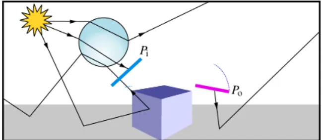
Fig. 1 Portals allow the manipulation of lighting effects in a scene. Here, the caustic created by the sphere is captured (blue portal) and moved (pink portal) under the cube, revealing the shiny Suzanne mon-key. The edit is smoothly integrated in the rendering of the scene.
tirely fixed, lighting designers add and tune light sources one by one [2].
Even though lighting parameters are perfectly set, the physically-based rendering does not necessarily match the artistic goal. In other words, the artistic freedom is limited to the physical simulation of light transport. As a consequence, methods have been developed to either modify the renderer input (scene configuration) or output (layered images) to ob-tain a desired result.
Even if widely used, post-processing techniques are lim-ited to image-based processing and cannot provide the full set of changes the artists would need. On the other hand, the lighting design is also tweaked and tricked, adding for in-stance lights not casting shadows [4], only giving specular lighting or lights that only affect a given object (i.e. light linking). The involved trial-and-error process is tedious,
re-2 Thomas Subileau et al.
quires a lot of experience and several time-consuming re-computations of physically-based renderings.
Following the pioneer methods exploring the editing and control of direct illumination, recent results propose to mod-ify the global illumination of a scene in order to add artis-tic control through the process. However, despite their ef-ficiency, these approaches are limited to a restrained set of effects.
In order to tackle these limitations, we propose to edit lighting effects directly in path-space, i.e. by changing how light propagates in the scene. These changes affect only the rendering stage and do not require to edit either the geometry or the lighting setup.
Our key idea is to allow artists to directly manipulate the light propagation (e.g. geometrical optics) of user-selected lightpaths through the use of portals that capture and tele-portlightpaths through 3D-space (Figure1and2). We de-fine portals as a manipulator composed of an input surface, a selection filter and an output surface. Every path that hits the input surface and corresponds to the user-defined path filter is teleported to the output surface.
While modifications might not be physically correct, we still rely on physically-based renderers and edits thus re-main visually coherent in the resulting rendering. Also, if not intentionally modified by the user, the light energy is conserved and sampling functions are not modified. This en-sures the conservation of consistence and convergence prop-erties of the original rendering technique.
We present in this paper two main contributions: a re-formulation of the path-space integral enabling light propa-gation editing (Section3.2), and a mechanism to alter light transport which we call portals (Section3.3). Our formula-tion is versatile and allows a wide range of manipulaformula-tions. For instance, we show that existing related techniques can be defined as specific portal configurations. By definition, por-tals are totally decorrelated from the scene description. They can be easily tuned and animated with keyframing. The tech-nique correctly handles shadow rays (Section4) and could be integrated in any path-based renderer.
Finally, we show how our approach can be used for ad-vanced modifications of complex lighting effects resulting from global illumination (Section5).
Pi
Po
Fig. 2 Portals alter the light propagation. When a ray intersects Pi(in
blue) and matches the selection filter, it is teleported to Po(in pink).
2 Previous work
In the context of digital content creation, artists have to man-ually setup materials and lights parameters of a 3D scene to obtain at the end the expected rendering effects. This work can be tedious and requires to estimate correctly how light interacts and propagates in the scene.
Previous work on intuitive editing allows user to paint an expected lighting effect in the scene, and optimizes its configuration to produce an as-correct-as-possible render-ing output [17,15,16,19]. These approaches provide effi-cient design interfaces but remain limited to the impact of scene parameters on the final rendering. This impact can be hard to control, especially in a global illumination con-text. Our work is orthogonal to these methods as we choose not to modify the lights and materials description but only edit light propagation during the rendering process. Several editing methods [18,14,12] focus on shadow manipulation. These methods provide different means to control shadows shape, position and smoothness. We focus on the editing of light transport, shadows shape cannot be directly manipu-lated in our approach.
Seminal works in lighting editing algorithms, limited to either direct lighting or specular reflection have inspired our work. Extending early work of Barzel [1], BendyLights [9] offers a direct lighting manipulation by bending the light propagation for spotlights and hence facilitates the control of direct illumination effects. Ritschel et al. [21] allow the user to change the reflected direction of purely specular surfaces. Ritschel et al. [22] define on-surface signal deformation to manipulate the appearance of any signal over the surface of 3D objects. The manipulation itself stays on surface and is prone to sliding artifacts when applied on animated sur-faces. As our approach is totally defined in 3D-space, we do not have these kinds of drawbacks. Using a robust vi-sualization tool, Reiner et al. [20] show that light propaga-tion can be well comprehended and particle flows creating specific lighting effects can be spatially and semantically clustered. Following this approach, Schmidt et al. [23] pro-pose a path retargeting technique: the user manipulation of a shading effect (referred as lighting effect in our paper) af-fects the outgoing tangent frame of the previous interaction surface. While allowing various edits, there are some lim-itations in the freedom of the manipulation. For instance moving a lighting effect below or through an object is not achievable as the object will intersect the edited paths. To overcome this limitation, the authors choose to add a spe-cific proxy-object approach to specify that an object does not interact with the edited paths.
We define a general theoretical framework for path space editing. We also formulate previous approaches [22,23] in this framework. We propose a manipulator which provides a flexible mechanism to edit path space. This mechnanism
allows artists to position the manipulator anywhere between the source surface (as in Schmidt et al. [23]) and the des-tination surface (as in Ritschel et al. [22]) of an effect and handles all sort of situations inbetween. This editing free-dom tackles the previous works limitations stated above.
3 Editing light propagation in path-space 3.1 Path-space formulation
As introduced by Veach [24], the light transport problem can be expressed as an integral over space. This path-integral defines the color of a pixel on the computed image as the integral of the flux transported by each lightpath from sources to this pixel. The measurement Ijfor each pixel j of
an image is written as Ij=
Z
Ω
fj(x)dµ(x), (1)
with Ω the set of all transport paths also called path-space, and dµ the area-product measure of a path x. Paths are of the form x = x0x1. . . xk, with 1 < k < ∞ and xi∈S , S being
the union of all surfaces. The ithsegment hxi, xi+1i of a path
is a straight line between the two consecutive positions xi
and xi+1. The contribution of a lightpath is measured as
fj(x) =L(x0→ x1)G(x0↔ x1) k−1
∏
i=1
fs(xi−1→ xi→ xi+1)G(xi↔ xi+1)
!
W(xk−1→ xk),
with L the emitted light, G the geometric or propagation term, fs the scattering function (e.g. the bsdf ) and W the
importance of the path for the pixel j.
If we ignore participating media, the propagation of the light between two surfaces along a path segment is influ-enced only by the relative incoming and outgoing light di-rections, the length of the segment, and the surfaces visibil-ity V at the interaction points:
G(xi↔ xj) = V (xi↔ xj)
(ni· |xj− xi|) (nj· |xi− xj|) ||xi− xj||2
, with · the dot product, |x| =||x||x , nithe normal vector of the
surface at xi, and V (xi↔ xj) the visibility function.
3.2 Path-based propagation editing
As seen in Section2, lighting can be edited by changing the light properties L, the scattering functions fs or the
propa-gation G. Artists usually tune lights and materials properties to obtain a desired lighting effect while propagation is left untouched. In this work, we propose a new formalism en-abling the definition of a large panel of transformations to
modify how light propagates in the scene, independently of the lighting and material configuration. The general idea is to capture light flux somewhere in the scene and release it somewhere else, this idea is translated in the path-integral as a modification of the propagation function.
Changing how light is transmitted without changing ma-terials and lights is equivalent to move a light contribution from a point xj to another point xe∈S . This can be done
by modifying the propagation function G(xi↔ xj) to a new
editable propagation function G(xi↔ xj, xe), where the
con-tribution reaching xj is moved to xe. As shown in Figure3,
modifications of the light propagation can be applied from any point pe= xi+ t|xj− xi| on the segment hxi, xji.
Let now assume that we know the edited receiver posi-tion xe and the editing position pe. To edit the propagation
of the initial lightpath, we remove its contribution at the po-sition xjand add it at the new receiver position xe. As a
con-sequence, the propagation between xi and xj is cancelled,
hence G(xi ↔ xj) = 0. The light is now transmitted to xe
and combined to other incoming paths. We now present how this concept translates to the lightpath contribution measure fj(x), and then focus on the definition of G.
Edited ligthpath propagation – We want to modify only how the light is received, so the scattering function fs is
eval-uated at xi with the initial incoming and outgoing
direc-tions, even for edited segments. Thus, in the path contribu-tion measurement of a lightpath (see §3.1), we replace the term fs(xi−1→ xi→ xi+1)G(xi↔ xi+1) with
fs(xi−1→ xi→ xi+1)G(xi↔ xi+1) + mi
∑
n=1
fs(xi−1→ xi→ xi↔i+1n )G(xi↔ xni↔i+1, xi+1)
where mi is the number of segments starting from xi and
edited to xi+1. G is the editing propagation function
describ-ing how the light propagation from xi to the nth original
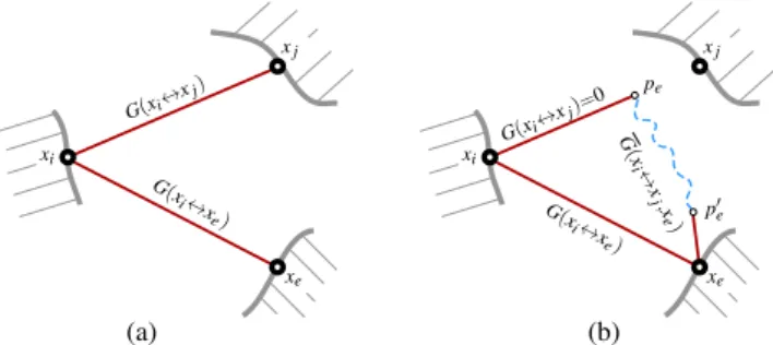
G(xi↔ xe) G(xi↔x j) xi xe xj (a) (b) G(xi↔ xe) G(xi↔x j)=0 xi xe xj G (x i↔ x j,x e) pe p0e
Fig. 3 (a) Non-edited scene, where the light propagation along seg-ments hxi, xji and hxi, xei is computed using G. (b) Edited scene:
prop-agation along hxi, xji is cancelled at pe, and transformed to p0ein order
to finally fall on xe. This whole process is defined by the edited
prop-agation term G . Red lines represent propprop-agation segments, potentially shared between multiple lightpaths.
4 Thomas Subileau et al.
Input
(b)
(a)
(c)
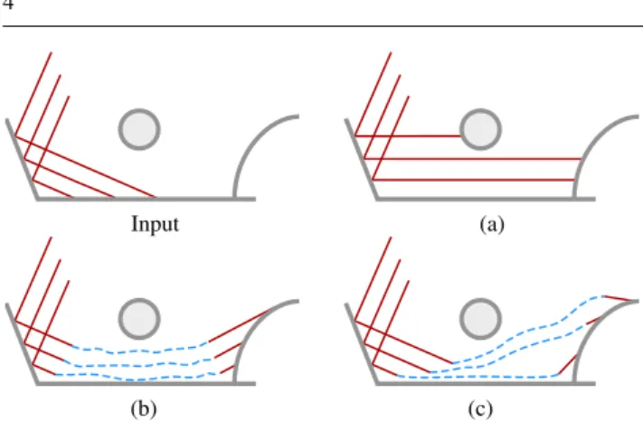
Fig. 4 Several path-space modifications configuration. An input scene is modified by changing how light is transmitted to a target surface. Red segments are actual lightpaths. Blue dashed lines correspond to lightpath transformations. By increasing complexity: (a) Light rays are re-oriented. (b) Light field is sliced and teleported. (c) Each ray is tele-portedand locally re-oriented according to the geometry.
unedited position xni↔i+1 is modified to reach xi+1, as
de-picted by the dashed blue line in Figure 3. We apply an analogous modification to the first segment x0↔ x1and note
fj(x) the resulting contribution measure (see full definition in Appendix).
Editable transmission function – One could define G(xi↔
xj, xe) as G(xi, xe), but as shown in Figure4a, this covers
only a subset of the possible modifications. As already stated, we want to modify only how the light is received, so we need to keep |xj− xi| as outgoing direction to evaluate the
propa-gation from xi. We note nethe normal vector at xe, and define
the editable propagation function as
G(xi↔ xj, xe) =V (xi↔ pe)V (p0e↔ xe) (2) (ni· |xj− xi|) (ne· |de|)
(||xi− pe|| + ||p0e− xe||)2
where de is the edited incoming light direction at xe. We
define p0eand deas
p0e=Mxj,xe(pe) (3)
de=Mxj,xe(pe) − xe,
whereMxj,xe transforms the light segment initially coming in xj to xe.Mxj,xe is what we call a portal, and can be con-figured to obtain a wide range of modifications of the light propagation, described in the next section. By construction, the non-edited scenario can be retrieved by settingMxj,xeas the identity function and xeas xj.
3.3 Portal-based propagation editing
According to Reiner et al. [20], humans are good at identify-ing and groupidentify-ing lightpaths correspondidentify-ing to lightidentify-ing effects (e.g. caustics) in the 3D scene. Assuming a path selection
mechanism, portals can be applied in two ways on groups of lightpaths.
In a general setting, one can defineMxj,xeper-pathin or-der to locally adapt the transformation to the scene, e.g. the geometry surrounding xjand xe. Here the artistic freedom is
maximal, however care must be taken to define a practica-ble transformation according to path-based rendering algo-rithms. For instance, Ritschel et al. [22] evaluate lighting at xe as if it is physically located at xj (see Figure4c). Hence
pe= xjand dehas the same angle with nethan |xi− xj| with
nj. As a result,Mxj,xedefines a mapping of the shading con-figuration from xjto xe. This function is not trivial to define,
and is computed by optimization in Ritschel’s approach. In a simplified setting, the propagation of the light can be edited uniformly within a group of paths, in that case we noteM the functional transformation applied to a group of paths. According to Reiner et al. [20], grouped paths usually share common properties (e.g. geometry), and can thus be edited uniformly to transform the resulting lighting effect. For instance, Schmidt et al. [23] propose to rotate the output direction from xito reach xe(see Figure4a). In other words,
M is defined as the identity function and pe= xi, thus
p0e=M (pe) = xi (4)
de=M (pe) − xe= xi− xe
Using our formalism one can see that both aforementioned existing techniques represent very specific edits and do not span a wide range of modifications of the light propagation. We propose to edit the light propagation with a more ex-pressive portal definition, according to the following con-straints. First, portals must be compatible with any path-based rendering algorithm, so we need to ensure thatMxj,xe is invertible. This allows bi-directional path traversal, a step usually required to compute shadow rays. Second, we want to include the path selection mechanism in our definition, to provide a unified path-based selection and editing metaphor. Third, we want to combine both geometric and photometric effects at once.
Geometrically, we define portals as a pair of surfaces parametrized over the same domain, the former Pigrabbing
incoming light segments and the latter Po releasing them
somewhere else in the scene. Selecting a group of paths is achieved by intersecting them with Pi. The resulting
inter-section points define the editing positions peused in
Equa-tion2. We noteGxj,xe the invertible geometric transforma-tion moving a segment from xj to xethrough Piand Po. We
also defineRxj,xean arbitrary photometric transformation of the incoming light segment, leading to
Mxj,xe(pe) =Gxj,xe(pe)Rxj,xe(p).
In practice, the complexity ofGxj,xe can be adapted ac-cording to the surfaces geometric properties. For instance,
x1 x2 G(x1↔ x2) G(x1↔ xj, x2) xj pe p0e
Fig. 5 When evaluating the propagation between two points, we need to take portals into account. Here, G(x1↔ x2) is nil but going through
the portals, a shadow ray lands on x2and transmits light from x1to x2.
uniformly parameterized planar surfaces define Gxj,xe as a linear transformation matrix encoding the rotation, transla-tion and scale between multiple surfaces, noted M in the fol-lowing. We can attach to portals additional embedded func-tions to easily supplement the definition of Mxj,xe. These transformations may be used to modify both the geometric termGxj,xeand the photometric termRxj,xe(Section5).
Finally, spatial path selection can be extended with a se-mantic path selection using path regular expressions. This notion has been introduced by Heckbert [6] and extended by Veach [24]. Each path is characterized by a set of symbols, each symbol represents the interaction that occurs at a ver-tex of the path. Regular expressions based on these symbols can then be attached to any portal and used to filter indepen-dently each incoming paths. We use the syntax proposed by Schmidt et al. [23] that adds light and object identifiers to each interaction, plus a specific symbol to represent portal traversal. Since paths sharing similar scattering events and similar trajectory in 3D-space produce a coherent variation of shading in the 3D scene, we formally define a lighting ef-fect by the set of lightpaths going through a given region in 3D-space, i.e. intersecting Pi, and matching a given regular
expression.
4 Implementation
We have implemented portals in Mitsuba software [7] for three rendering algorithms: Photon mapping [8], Progres-sive photon mapping [5] and Bi-directional path tracing [10]. We have interfaced portals with Blender [3] and Mitsuba ex-port addon to allow an interactive setup and manipulation of portals. For each portal, we add a manipulator in the 3D scene defined as a pair of planar surfaces Pi, Po
parameter-ized over the same domain, typically [0, 1]2. We note Pi(u, v)
a point defined by the parametric coordinates (u, v) on Pi.
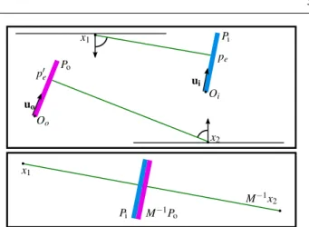
Theoretically, the path-integral formulation of light trans-port considers the path-space Ω to be entirely known. In practice, it is partially evaluated by sampling. The imple-mented algorithms construct samples of Ω with a two-step routine: x1 x2 x1 Po Pi Pi M−1Po Oo uo Oi ui M−1x2 pe p0e
Fig. 6 We are searching the ray leaving x1, intersecting Piand
trans-formed by the portal such that, when leaving Po, it lands on x2. It is
defined by the intersection between the segment hx1, M−1x2i and Pi.
– During the first step, paths are built by casting rays from a source (light or camera) toward the scene and bouncing iteratively on the geometry. The correct evaluation of G dur-ing this step is direct. When a ray intersects Pi at position
pe= Pi(u, v), it is recast from edited position p0ein the same
direction relatively to the local tangent frame.
– During the second step, a shadow ray is cast between each couple of vertices x1and x2to evaluate if the segment hx1, x2i
transports energy. In Photon mapping, this corresponds to final gathering whereas in Bi-directional path tracing, this corresponds to the connection step between the camera sub-path and the light subsub-path.
When using portals, we need to correctly evaluate the propagation between x1and x2. As shown in Figure3, we
need to evaluate G(x1↔ x2) and G(x1↔ xj, x2) for every
edits. Evaluating G is done as usual by casting a ray from x1toward x2. Evaluating G corresponds to finding rays that
leave x1toward unknown points xjand intersect Pisuch that,
when leaving Po, they land on x2. Figure5 represents the
geometric setup of this case. Finding all the shadow rays that connect the two vertices ensures the correct evaluation of the rendering equation.
To solve this problem, we define g(u, v) → R+a function that returns the distance between a position along the ray r(u, v) and the vertex x2, with r(u, v) = Po(u, v)+t M(Pi(u, v)−
x1) and t ∈ R+. The set of rays possibly connecting x1and x2
are defined by (u, v) ∈ ker(g), i.e. (u, v) such that g(u, v) = 0. We have implemented the solution for our planar portal objects. Considering the points peand p0edefined as:
pe= Pi(u, v) = Oi+ u ui+ v vi
p0e= Po(u, v) = Oo+ u uo+ v vo
with Oi the origin of portal Pi and ui, vi the
parameteriza-tion vectors, respectively Oo, uoand vofor portal Po, we are
searching for u, v and t such that: x2= p0e+ tM(pe− x1)
6 Thomas Subileau et al.
Fig. 7 The same portal is used in a scene with three different objects projecting a caustic. The modification applies consistently and shows that portals are highly independent from the scene.
Multiplying both sides by M−1:
M−1x2= pe+ t(pe− x1)
Developing and factorizing by pe:
1 1 + tM −1x 2+ t 1 + tx1= pe
This corresponds to the intersection between the segment hx1, M−1x2i and the surface of Pi, as shown in Figure6. We
solve this equation using the algorithm presented by Lagae and Dutr´e [11]. After finding the (u, v) coordinates, we need to evaluate V (x1↔ pe) and V (p0e↔ x2) to verify that no
geometry blocks the visibility.
5 Results
In this section, we will present several results showing how portals can reproduce previous work (Section 5.1) as well as other various geometric (Section 5.2) and photometric (Section 5.3) transformations. In any example, portals are freely positioned in 3D-space and are thus highly indepen-dent from the scene. This is shown in Figure7 where the same portal is applied to different geometries.
5.1 Implementation of previous work
Ritschel et al. [21] allow the user to define what part of the scene is seen through mirror reflections. This translates into editing the propagation term G(xk−1↔ xk) in a path
of length k and only if the interaction at xk−1is a specular
reflection. Such edits are handled with portals filtering ES paths. Examples are shown in the supplemental video.
As shown in Section3, Schmidt et al. [23] translates smoothly in our formulation. We show an example of light retargeting using portals in Figure8b. Here, M is defined as the identity matrix and the edited rays are rotated using a constant function embedded in the portal. Light retargeting does not conserve the geometric terms in the computation of G, i.e. either the distance or the relative directions to the sur-faces are preserved (see Eq.2). Therefore, after retargeting, the illuminance of the lighting effect is not conserved and the resulting caustic is visually different from the original.
(b) (a)
(c)
Fig. 8 Application of Figure4. (a) Original rendering. (b) Light retar-geting with portals. (c) Light field teleportation with portals.
(b)
(a) (c)
Fig. 9 A portal captures the caustic and replicates it with multiple out-put surfaces, disposed around the glass egg. (a) Original scene. (b) Du-plication. (c) Duplication and shifting spectrum hue.
In Figure8c, we move the output portal in order to conserve all terms for one point xi. For other points, terms will vary
depending on the curvature of the surfaces. We can see that after teleportation, the caustic illuminance remains visually similar to the original.
5.2 Geometric transformation
A typical editing of the propagation using portals is illus-trated Figure1. Caustic paths are teleported onto the Suzanne model. We can see that, after transformation, paths continue to interact with the geometry, hence creating caustic sparkles on the walls due to the facetted model. As we evaluate the propagation toward the original position, the blue cube does not block the propagation. The setup of this portal is shown in the supplemental video.
Portals also allow to replicate a lighting effect. To do this, we associate in a portal one input surface to multi-ple output surfaces, each resending captured rays. Figure9b
(a) (b) (c)
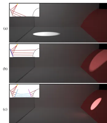
Fig. 10 Using a stochastic map allows to progressively select and transform the paths. (a) Original result. (b) Raw editing. (c) Smooth editing.
shows how a lighting effect is copy/pasted in the scene. Du-plicated output surfaces act as new lights and thus do not conserve overall energy.
Portals are finite surfaces and may create sharp disconti-nuities when overlapping lighting effect boundaries. For in-stance, if the input portal covers only one part of the caustic (Figure10a), it will create a sharp visual discontinuity after editing, as shown in Figure10b. A soft selection can be done using a stochastic function defining the probability for a ray to be edited or not. In practice, this function is defined using a grayscale texture. Figure10c shows how such a probability map allows to smoothly apply the editing when overlapping a lighting effect.
A normal map can also be used to modify the outgoing local tangent frame and thus tilt rays directions as shown in Figure11d. In this case, M is modified ununiformly and is not a linear transformation anymore, hence shadow rays are not edited by portals in this result.
5.3 Photometric transformation
Textures can also be used to transform the intensity (Fig-ure11b) or the hue (Figure11c) of lightpaths. An example of duplication coupled with different photometric transforma-tions is shown in Figure9c. The statue example (Figure12) shows how a color bleeding is colored. Portal input and out-put surfaces are placed in front of the statue head and a tex-ture is used to transform the color bleeding hue from the green wall. Other examples of photometric transformations are shown in Figure7and in the supplemental video.
5.4 Performance
In our experimental implementation, using portals adds two types of computational overhead:
1. a selection cost depending on the number of rays inter-secting the portals, and due to the regular expressions matching evaluation,
2. an editing cost depending only on the number of edited rays, caused by the modification of the rays during their interaction with the portal.
(b)
(d) (c)
(a)
Fig. 11 Using textures to control lighting effect. (a) Unmodified scene. (b) Using a texture to control the intensity. (c) Using a texture to control the hue. (d) Using a normal map to modify outgoing directions.
For the edited rendering shown in Fig.1, the combination of the constant and varying overheads represents around 12% of the non-edited timings, as shown in Table1. It remains the same when using more samples (e.g. 1024 or 8100 sam-ples per pixels), since both For the same scene rendered us-ing Photon Mappus-ing, the overhead is slightly more impor-tant and raise to 20%, as shown in Table2. We can see that for both techniques, the overhead is relatively constant for a given scene, and not impacted by the number of samples.
In a second experiment we measured the variation of overhead according to the number of edited rays. For a fixed geometry and light setups, we applied a stochastic function on the portal in order to vary the amount of selected rays, as done in Figure10for smooth caustic selection. Tables3and
1024 spp 8100 spp Original Edited Original Edited Rendering time (m) 15.79 17.64 125.26 141.64
Overhead (%) - 11.74 - 13.07
Table 1 Performance table for Fig.1in Bi-directional Path Tracing for two levels of samples per pixels (spp). Original is top left figure, edited is bottom left figure.
~270M photons ~500M photons Original Edited Original Edited Rendering time (sec) 264.61 319.46 431.22 516.00
Overhead (%) - 20.73 - 19.66
Table 2 Performance table for Fig.1in Photon Mapping for two dif-ferent quantities of caustic photons. Original is top left figure, edited is bottom left figure.
8 Thomas Subileau et al.
Fig. 12 Color bleeding is edited through a spectral transformation. The regular expression filter is LD. There is a color shift to transform the greenish bleeding to a reddish one. From left to right: unmodified scene, portal surfaces (in red), result.
BDPT (81 spp) Unedited selecting 100% selecting 85% selecting 40% selecting 6%
Rendering time (sec) 74.23 82.44 82.10 81.40 80.83
Regexp overhead (%) - 8.81 8.61 6.96 6.47
Editing overhead (%) - 1.95 1.75 0.79 0.12
Overhead (%) - 11.06 10.60 9.66 8.89
Table 3 Detailed execution time, with various selection setting (Bi-directional Path Tracing)
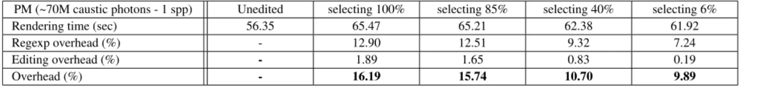
PM (~70M caustic photons - 1 spp) Unedited selecting 100% selecting 85% selecting 40% selecting 6%
Rendering time (sec) 56.35 65.47 65.21 62.38 61.92
Regexp overhead (%) - 12.90 12.51 9.32 7.24
Editing overhead (%) - 1.89 1.65 0.83 0.19
Overhead (%) - 16.19 15.74 10.70 9.89
Table 4 Detailed execution time, with various selection setting (Photon Mapping)
4report the cost of rays selection and editing, and the total overhead for probability of selection ranging from 100% to 6%, respectively for Bi-directional Path Tracing and Photon Mapping. The bottleneck of our technique remains in the evaluation of the regular expression. This is understandable as regular expression matching tests are knowingly compu-tationally expensive and need to be evaluated for every rays intersecting the surface, in order to know wheter or not the ray needs to be edited.
5.5 Discussion
User control – In the current implementation, portals are manipulated directly through the use of two geometric han-dles, similarly to the positioning of objects in 3D model-ing software (as shown usmodel-ing Blender in the supplemen-tal video). The regular expression filter can be defined us-ing presets (e.g. mirror-reflections are ES+, purely specu-lar caustics are LS+) or manually. A more intuitive auto-matic user-interface could be envisioned. First, the user se-lects an area on the 3D surface, for instance, with a sketch in image-space. Second, the portal is extracted from paths going through this area : the regular expression from the paths prevailing syntax and the surface from the paths foot-print. Third, the drag-and-drop of the area in the scene de-fines the transformationGxj,xeassociated to the portal. Such process is similar to the interface proposed and validated by Schmidt et al. [23].
Prefixed regular expression – When a ray hits an input por-tal, we compare the expression of the path from its starting point to the last known vertex to decide if the path is to be transformed. The regular expression thus represents the path interactions before intersecting the portal and not the full path within the scene. A back-tracking mechanism would allow to compute light scattering events occurring after the portal surface and decide to filter the path afterward based on its full definition. However, we found in our experiments that capturing lighting effects with a prefix regular expres-sion is effectively done.
Bi-directional traversal – Consequently, portals apply ei-ther on light subpaths (filter starting with L) or camera sub-paths (filter starting with E). It is possible for subsub-paths to intersect opposite-type filtering input portals backwards and then be linked with opposite-type subpaths, potentially mak-ing the full path eligible to the portal transformation. To ad-dress this problem, segments that cross opposite-type input portals backwards are tagged. After the linking step, tagged segments are reevaluated both ways and, if they match the filter, visibility is recomputed as explained Section4.
6 Conclusion and Future work
We have analyzed the problem of editing light transport and have shown how it can be uniformly defined within the path-integral formulation of the rendering equation. According to this definition, we have proposed a method called ray
por-talsthat allows the capture and modification of lightpaths both in 3D-space and path-space.
In the current implementation, portals do not handle par-ticipating media. However, the proposed formulation could be adapted by ensuring that the editing function Mxj,xe is continuous and calculable for any point p0ebetween peand
xe. Following an approach similar to light beams
manipula-tion [13] could be envisioned to do such extension.
Another interesting direction for future work is extend-ing portals to more various geometries. Especially, non-planar geometries would allow the definition of complex editing functionMxj,xeas the one used in Ritschel et al. [22], fitted to match the target surface. It would allow edits as shown in Figure4c that locally conserve illuminance of a lighting effect through editing. It would also ease the capture and ma-nipulation of multidirectional effects, such as low-frequency ambient lighting. However, to fully integrate within a path-based rendering framework, portal transformations need to be inverted which can be challenging for complexMxj,xe.
Ray portalspropose a unified and efficient solution which allows complex editing of light transport phenomena through the manipulation of simple geometric portals and user-defined controls. The proposed method complements and extends previous state of the art techniques, especially as it is largely scene independent and ensures a correct evaluation of light propagation.
Acknowledgments We especially thank the Observatory of Systems Information Retrieval and Indexing of Multime-dia contents (OSIRIM) platform of the Toulouse Institute of Computer Science Research (IRIT).
Appendix
The edited path contribution measure is defined as
fj(x) = L(x0→ x1)G(x0↔ x1)+ m0
∑
n=1 L(x0→ xn1)G(x0↔ x1n, x1) k−1∏
i=1 fs(xi−1→ xi→ xi+1)G(xi↔ xi+1)+ mi
∑
n=1
fs(xi−1→ xi→ xi↔i+1n )G(xi↔ xni↔i+1, xi+1)
W(xk−1→ xk).
References
1. Barzel, R.: Lighting controls for computer cinematography. J. Graph. Tools 2(1), 1–20 (1997)2
2. Birn, J.: Digital Lighting and Rendering (2nd Edition). New Rid-ers Publishing, Thousand Oaks, CA, USA (2005)1
3. Blender Online Community: Blender - a 3d modelling and render-ing package (2015). URLhttp://www.blender.org 5
4. Damez, C., Slusallek, P., Walter, B.J., Myszkowski, K., Wald, I., Christensen, P.H.: Global illumination for interactive applications and high-quality animations. In: SIGGRAPH ’03: ACM SIG-GRAPH 2003 Course Notes. ACM (2003)1
5. Hachisuka, T., Ogaki, S., Jensen, H.W.: Progressive photon map-ping. ACM Trans. Graph. 27(5), 130:1–130:8 (2008)5
6. Heckbert, P.S.: Adaptive radiosity textures for bidirectional ray tracing. SIGGRAPH Comput. Graph. 24(4), 145–154 (1990)5
7. Jakob, W.: Mitsuba renderer (2010). Http://www.mitsuba-renderer.org5
8. Jensen, H.W.: A practical guide to global illumination using ray tracing and photon mapping. In: ACM SIGGRAPH 2004 Course Notes, SIGGRAPH ’04. ACM, New York, NY, USA (2004)5
9. Kerr, W.B., Pellacini, F., Denning, J.D.: Bendylights: Artistic con-trol of direct illumination by curving light rays. Computer Graph-ics Forum 29(4), 1451–1459 (2010)2
10. Lafortune, E.P., Willems, Y.D.: Bi-directional path tracing. In: Proceedings Conference on Computational Graphics and Visual-ization Techniques, pp. 145–153 (1993)5
11. Lagae, A., Dutr´e, P.: An efficient ray-quadrilateral intersection test. Journal of Graphics Tools 10(4), 23–32 (2005)6
12. Mattausch, O., Igarashi, T., Wimmer, M.: Freeform shadow boundary editing. Computer Graphics Forum 32, 175–184 (2013)
2
13. Nowrouzezahrai, D., Johnson, J., Selle, A., Lacewell, D., Kaschalk, M., Jarosz, W.: A programmable system for artistic vol-umetric lighting. ACM Trans. Graph. 30(4), 29:1–29:8 (2011)9
14. Obert, J., Pellacini, F., Pattanaik, S.: Visibility editing for all-frequency shadow design. In: Proceedings of the 21st Euro-graphics Conference on Rendering, EGSR’10, pp. 1441–1449. Eurographics Association, Aire-la-Ville, Switzerland, Switzerland (2010)2
15. Okabe, M., Matsushita, Y., Shen, L., Igarashi, T.: Illumination brush: Interactive design of all-frequency lighting. In: Proceedings of the 15th Pacific Conference on Computer Graphics and Appli-cations, PG ’07, pp. 171–180. IEEE Computer Society (2007)2
16. Pellacini, F.: envylight: An interface for editing natural illumina-tion. ACM Trans. Graph. 29(4), 34:1–34:8 (2010)2
17. Pellacini, F., Battaglia, F., Morley, R.K., Finkelstein, A.: Lighting with paint. ACM Trans. Graph. 26(2) (2007)2
18. Pellacini, F., Tole, P., Greenberg, D.P.: A user interface for inter-active cinematic shadow design. ACM Trans. Graph. 21, 563–566 (2002)2
19. Raymond, B., Guennebaud, G., Barla, P., Pacanowski, R., Granier, X.: Optimizing BRDF Orientations for the Manipulation of Anisotropic Highlights. Computer Graphics Forum (2014)2
20. Reiner, T., Kaplanyan, A., Reinhard, M., Dachsbacher, C.: Selec-tive inspection and interacSelec-tive visualization of light transport in virtual scenes. Comp. Graph. Forum 31(2pt4), 711–718 (2012)2,
4
21. Ritschel, T., Okabe, M., Thorm¨ahlen, T., Seidel, H.P.: Interactive reflection editing. ACM Trans. Graph. 28(5), 129:1–129:7 (2009)
2,6
22. Ritschel, T., Thorm¨ahlen, T., Dachsbacher, C., Kautz, J., Sei-del, H.P.: Interactive on-surface signal deformation. ACM Trans. Graph. 29(4), 36:1–36:8 (2010)2,3,4,9
23. Schmidt, T.W., Nov´ak, J., Meng, J., Kaplanyan, A.S., Reiner, T., Nowrouzezahrai, D., Dachsbacher, C.: Path-space manipulation of physically-based light transport. ACM Trans. Graph. 32 (2013)2,
3,4,5,6,8
24. Veach, E.: Robust monte carlo methods for light transport simu-lation. Ph.D. thesis, Stanford, CA, USA (1998). Chap. 4,8 3,