HAL Id: hal-00930014
https://hal.archives-ouvertes.fr/hal-00930014
Submitted on 14 Jan 2014
HAL is a multi-disciplinary open access
archive for the deposit and dissemination of
sci-entific research documents, whether they are
pub-lished or not. The documents may come from
teaching and research institutions in France or
abroad, or from public or private research centers.
L’archive ouverte pluridisciplinaire HAL, est
destinée au dépôt et à la diffusion de documents
scientifiques de niveau recherche, publiés ou non,
émanant des établissements d’enseignement et de
recherche français ou étrangers, des laboratoires
publics ou privés.
LES and acoustic analysis of thermo-acoustic
instabilities in a partially premixed model combustor
Ignacio Hernández, Gabriel Staffelbach, Thierry Poinsot, Juan C. Román
Casado, Jim B.W. Kok
To cite this version:
Ignacio Hernández, Gabriel Staffelbach, Thierry Poinsot, Juan C. Román Casado, Jim B.W. Kok.
LES and acoustic analysis of thermo-acoustic instabilities in a partially premixed model combustor.
Comptes rendus de l’Académie des sciences. Série IIb, Mécanique, Elsevier, 2013, vol. 341, pp.121-130.
�10.1016/j.crme.2012.11.003�. �hal-00930014�
To link to this article :
DOI:
10.1016/j.crme.2012.11.003
URL : http://dx.doi.org/10.1016/j.crme.2012.11.003
To cite this version :
Hernández, Ignacio and Staffelbach, Gabriel and Poinsot, Thierry
and Román Casado, Juan C. and Kok, Jim B.W.
LES and acoustic
analysis of thermo-acoustic instabilities in a partially premixed
model combustor
. (2013) Comptes Rendus de l'Académie des
Sciences - Séries II, Mécanique, vol. 341 (n° 1-2). pp. 121-130.
ISSN 1631-0721
O
pen
A
rchive
T
OULOUSE
A
rchive
O
uverte (
OATAO
)
OATAO is an open access repository that collects the work of Toulouse researchers and
makes it freely available over the web where possible.
This is an author-deposited version published in :
http://oatao.univ-toulouse.fr/
Eprints ID : 10682
Any correspondance concerning this service should be sent to the repository
administrator:
staff-oatao@listes-diff.inp-toulouse.fr
LES and acoustic analysis of thermo-acoustic instabilities in a
partially premixed model combustor.
I. Hern´
andez
a, T. Poinsot
b, J.C. Rom´
an Casado
c, J.W.B. Kok
c aCERFACS, 42, Avenue Gaspard Coriolis, 31057 Toulouse, France.
b
CNRS, Institut de m´ecanique des fluides, Toulouse, France.
c
University of Twente, Laboratory of Thermal Engineering, P.O. Box 217, 7500 AE Enschede, The Netherlands.
Received *****; accepted after revision +++++ Presented by I. Hern´andez
Abstract
Numerical simulations were performed using Large Eddy Simulation (LES) and acoustic analysis tools to study thermo-acoustic instabilities in an academic burner. The configuration studied corresponds to a methane/air burner installed at the University of Twente (The Netherlands). It operates under fuel-lean partially premixed conditions at atmospheric pressure, and was built to study thermo-acoustic instabilities in conditions representative of gas turbine Lean Premixed systems: gaseous fuel is injected upstream of the combustor and has a limited time to mix with air. Even though the objective is to burn in a premixed mode, the actual regime corresponds to a partially premixed flame where strong equivalence ratio variations are created especially during combustion instabilities. Capturing these modes with LES is a challenge: here, simulations for both stable and unstable regimes are performed. In the unstable case, the limit cycle oscillations (LCO) are characterized and compared to experimental results. Reasonable agreement is found between simulations and experiments.
R´esum´e
Simulations aux grandes ´echelles des instabilit´es thermo-acoustiques dans un brˆuleur partiellement pr´em´elang´e m´ethane/air. Des simulations num´eriques sont effectu´ees avec des outils d’analyse acoustique et de Simulation aux Grandes ´Echelles (SGE) pour ´etudier des instabilit´es thermo-acoustiques dans un brˆuleur acad´emique. La configuration ´etudi´ee correspond `a un brˆuleur install´e `a l’Universit´e de Twente (Pays Bas). Le dispositif fonctionne aux r´egimes pauvres `a pression atmosph´erique et a ´et´e con¸cu pour ˆetre enclin aux instabilit´es thermo-acoustiques. C’est une configuration proche des syst`emes LPP install´es dans les turbines ´a gaz : le fuel est inject´e pur en amont de la chambre mais a peu de temps pour se m´elanger avec l’air. Le syst`eme fonctionne donc avec de grandes variations de richesse, surtout pendant les modes instables. Pr´evoir ces modes avec la LES est un d´efi. Ici, des simulations sont faites pour des r´egimes stables et instables. Dans le cas instable, les oscillations du cycle limite sont caract´eris´ees et compar´ees aux r´esultats exp´erimentaux. Un bon accord est trouv´e entre simulations et exp´eriences.
Key words: Combustion ; Thermo-acoustics ; Limit cycles ; Large Eddy Simulation
Mots-cl´es : Combustion ; Thermo-acoustique ; Cycles limite ; Simulation aux Grandes ´Echelles
Version fran¸caise abr´eg´ee
La combustion turbulente dans un brˆuleur acad´emique m´ethane/air en r´egime pauvre et partiellement pr´em´elang´e est simul´ee `a l’aide d’un code de SGE. Cette installation reprend plusieurs caract´eristiques des syst`emes LPP (Lean Premixed) utilis´es dans les turbines `a gaz : en particulier, le m´elange est suppos´e rapide et le carburant (gazeux ici) est inject´e juste en amont de la chambre de combustion. En pratique, ce m´elange n’est pas parfait et il l’est encore moins lorsque la flamme entre en oscillation. Il faut donc des mod`eles de combustion adapt´es aux r´egimes partiellement pr´em´elang´es et pr´evoir ces r´egimes avec un code LES devient un d´efi. De plus, l’´ecoulement n’est pas swirl´e dans cette exp´erience, ce qui rend les choses plus d´elicates. En effet le swirl est souvent un facteur favorable aux codes LES. Deux points d’op´eration sont ´etudi´es.
Dans l’un d’eux, un r´egime de flamme stable est retrouv´e dans l’exp´erience ainsi que dans la simulation. Dans le deuxi´eme, une instabilit´e thermo-acoustique est observ´ee dans l’exp´erience, et elle est aussi pr´edite dans la simulation. Des oscillations p´eriodiques de pression et de vitesse axiale sont observ´ees, amenant `a des oscillations de d´egagement de chaleur. L’amplitude des oscillations croit dans le temps et arrive `a un plateau, donnant lieu `a un cycle limite. La fr´equence des oscillations observ´ee dans l’exp´erience est de 261 Hz, tandis que celle pr´edite par la simulation est de 305 Hz. La diff´erence est attribu´ee `a la mod´elisation des pertes thermiques, qui ne prend en compte que celles dues `a la conduction et la convection, alors que les pertes thermiques radiatives sont n´eglig´ees.
1. Introduction
Cleaner and more efficient combustion techniques in gas turbines for energy production and aircraft propulsion are needed, due to the the increasingly stringent emission regulations. In particular, lean-premixed combustion stands out as a successful solution to avoid the production of pollutants, such as N Ox, unburned hydrocarbons or soot. However, lean-premixed flames are prone to thermo-acoustic
instabilities [1]. Thermo-acoustic instabilities arise naturally and are self-sustained. It is a phenomenon whereby pressure and heat release rate fluctuations interact in confined domains such as combustion chambers. These two phenomena become strongly coupled, the acoustic oscillations leading to fluctuations in the heat release rate that, in turn, feed energy back to the acoustic field, as a result of an unsteady gas expansion [2]. For this phenomenon to be amplified, acoustic and heat release rate oscillations must be in phase, satisfying the so-called Rayleigh criterion [3], as expressed in Eq. (1).
Z
V
Z
T
p′q′dV dt >0 (1)
where p′ and q′ are the pressure and heat release rate fluctuations respectively, V is the volume of the
domain and T is the period of the oscillations.
This condition being satisfied, the amplitude of the oscillations will grow in time until the driving mechanism (combustion in this case) saturates due to non-linear effects. When acoustic losses match the
Email addresses: hernand@cerfacs.fr (I. Hern´andez), poinsot@imft.fr (T. Poinsot),
energy gain a steady-state oscillatory behaviour is attained, which is referred to as LCO, as sketched in Fig. 1 left. During LCO, large heat release rate and pressure fluctuations are observed, which can severely damage the combustion chamber components. Thermo-acoustic instabilities in lean-premixed combustors constitute then an interesting research topic with direct industrial applications.
Figure 1. Left: schematic driving and damping amplitudes dependence on the instability amplitude and the resulting limit cycle amplitude ALC, from Lieuwen [2]. Right: partially premixed flames in LPP systems. In the mixing tube, no combustion takes place. In the chamber, combustion begins in a partially premixed regime.
Predicting combustion instabilities in LPP systems using LES is the objective of multiple teams at the moment. Interestingly, LPP devices have specificities which make them different from many academic burners. One of them is that while most laboratory scale experiments operate either in fully premixed or in diffusion regimes, LPP systems often work in partially premixed regimes. Fuel is injected at a short distance upstream of the combustion chamber and mixing is assumed to be fast so that a perfectly premixed flow should enter the chamber. In practice, this is never the case and strong equivalence ratio fluctuations are observed in most burners [4]. For LES, this implies that two different regions must be computed in LPPs (Fig. 1 right): a first zone (normally in the mixing tube) where only mixing takes place and a second one (the combustion chamber) where combustion takes place. These two zones are separated by edge flames [5,6], usually triple flames, where combustion begins. The structure of these edge flames differs from classical triple flames however, because the recirculating hot gases participate to the stabilization process [7]. And during combustion oscillations, these zones move: combustion may start in the mixing tube or mixing in the combustion chamber. This makes chemistry modeling complicated: for example tabulated methods for chemistry have difficulties to address pure mixing zones. In the present work, the Thickened Flame model is tested for such flows. A second specificity of the Twente set up is that it is not swirled. Many recent LES of reacting flows have been performed for swirled flows [8,9,10,11] for which the flame position is almost imposed by the recirculation zone. It is not as simple for unswirled flows and it is interesting to check how LES performs for such cases in partially premixed regimes.
2. Experimental setup
The experiment, built within the framework of the european LIMOUSINE project, is devoted to the study of acoustic instabilities in gas turbines (Table 1). It was designed to be prone to thermo-acoustic instabilities. The V3 version of the burner is composed of two rectangular ducts of different width oriented vertically (Fig. 2(a)). The burner is closed at the bottom end and open to the atmosphere at the top outlet. Air is injected through 2 mm holes placed along transverse pipes located in a cavity at the upstream end. Fuel is distributed with a pipe running inside the triangular bluff body and injected through 62 holes (diameter: 1 mm), arranged symmetrically along the bluff body side walls. This wedge
is located at the junction between the upstream and downstream ducts, and serves to anchor the flame (Fig. 2(c)).
Table 1
Burner geometry dimensions indicated in mm.
Part Length Width Diameter Side
Upstream duct 210 25 — — Downstream duct 780 50 — — Air holes — — 2 — Fuel holes — — 1 — Wedge — — — 22 (a) (b) (c)
Figure 2. (a) Full burner geometry and location of pressure probes. (b) Wedge and fuel injection holes. (c). Cut of the burner around the fuel injection and flame stabilization zones.
The burner maximum power is 80 kW. The fuel is methane and air is used as the oxidizer. A campaign of tests was conducted in order to determine the stability range of the combustor. Power (or equivalenty, fuel mass flow rate) was fixed at 20 kW, 40 kW and 60 kW while the air mass flow rate was increased until the flame was blown out. Fig. 3 shows the stable and unstable regions in terms of power and air factor λ (inverse of the equivalence ratio φ). Hysteresis in the burner behaviour was observed as the air factor was increased or decreased. Pressure signals were recorded with pressure probes 1 to 6 located on the burner liner wall at different distances (Fig. 2(a)).
3. Numerical simulations
3.1. Numerical setup
The LES code AVBP [12] was used to solve the compressible, reacting flow equations on unstructured grids. This finite-volumes solver is based on a cell-vertex approach. An adaptation of the centered, second order in space and time Lax-Wendroff [13] numerical scheme to the cell-vertex formulation was employed.
Figure 3. Stability map obtained experimentally showing the stable and unstable operation regions of the burner.
The complete set of filtered mass, momentum, energy and chemical species conservation equations is solved. The Smagorinsky model [14] is used to model the sub-grid scale viscosity, whereas the effect of sub-grid scale turbulence on chemical reactions is modeled using a Dynamic Thickened Flame Model (DTFM) from Charlette et al. [15]. The chemistry is modeled using a reduced mechanism suitable for LES (2 steps and 6 species) for CH4/air flames from Franzelli et al. [16].
Given the periodic nature of the fuel holes arrangement and the fact that longitudinal acoustic modes are the most likely to appear, the computational domain can be reduced to a slice along the vertical axis of the full burner. The slice only comprises a pair of fuel holes and is 4 mm thick, which is the distance between two consecutive holes. A semicircular atmosphere was included in the domain at the burner outlet, see Fig. 4(a). The computational mesh is composed of tetrahedra and has 1M nodes. The mesh was refined in critical regions, where the mesh size was set to 0.18 mm (mixing region) and 0.4 mm (flame region), as shown in Fig. 4(c).
(a) (b) (c)
Figure 4. (a) Global view of the computational domain. (b) Close side view of the slice chosen as computational domain. (c) Detail of the mesh around the fuel injection and flame stabilization zones.
A law of the wall boundary condition was imposed on all solid walls to model the gas friction. All walls are adiabatic, except for the downstream duct and wedge walls, where heat losses were imposed. Thermal resistances were estimated considering conductive and convective heat transfer modes. Characteristic
boundary conditions (Poinsot and Lele [17]) were employed on all inlets and outlets. The fuel and air inlet mass flow rates were imposed in a soft way by means of a relaxation coefficient of κ = 1000, allowing then for mass flow fluctuations. A relaxation coefficient of κ = 10 was used at the atmosphere outlet. This soft acoustic boundary condition allows for pressure fluctuations, yet preventing the pressure within the domain to drift from its reference value (Pref = 101325 Pa). The inclusion of the atmosphere in the
computational domain eliminates the need to impose the correct reflection coefficient at the burner outlet, to be determined experimentally and, in general, frequency-dependent. Acoustic boundary conditions are a key parameter in the computation of thermo-acoustic instabilities. Here, acoustic reflection at the burner outlet is directly resolved by the LES. Periodic boundary conditions were set on the walls parallel to the flow and no interaction between adjacent fuel holes was taken into account.
The AVSP code was used to perform an acoustic analysis of the burner [18,19]. It is a Helmholtz solver for unstructured grids giving the acoustic eigenmodes and their associated eigenfrequencies. For the acoustic calculations, the same computational domain was employed, even though the mesh was a coarser version of the one used for the LES, since the characteristic wave lengths introduced by acoustics are longer than all flame lengths.
Two operating points were simulated corresponding to a power of 60 kW and air factors of λ = 1.25 and λ = 1.8 (Table 2). These points lie in the unstable and stable domains respectively, as seen in Fig. 3. The fuel and air mass flow rates were reduced proportionally to the size of the computational domain. All conditions (mesh, models, boundaries) are exactly the same for both simulations, only the air mass flow rate varies. Simulations ran on 120 processors and the computational cost was about 60000 CPU hours per simulation.
Table 2
Operating points data of the simulations performed.
Simulation 1 Simulation 2
Power 60 kW 60 kW
Air factor λ 1.25 1.8
3.2. LES 1: unstable case
Fig. 5(left) shows the fuel mass fraction field of an instantaneous solution of simulation 1 (which is experimentally unstable) and displays the jet in cross flow created by the methane injection with respect to the air stream (Fig. 2(c)). Mixing between fuel and air is enhanced due to the turbulence generated as the flow is squeezed through the gap between the wedge and the walls. The mixture starts burning immediately after the wedge but the scatter plot of heat release versus mixture fraction (Fig. 5(right)) reveals that combustion takes place over a wide range of mixtures and not only at the mean mixture fraction of the burner (0.045), confirming that partially premixed combustion dominates in this flow.
Fig. 6(a) shows an instantaneous temperature fields and reaction rate contours in the simulation 1. The flame is stabilized by both the central recirculation zone (CRZ) and corners recirculation zones (CORZ) leading to a short flame with respect to one only stabilized by the CRZ. This compact flame favors thermo-acoustic instabilities, because heat release takes place in a short region around the wedge. Energy can be fed to the acoustic field very efficiently, leading to the excitation of an acoustic mode. In the simulation1 such phenomenon was observed. Pressure oscillations grow in amplitude, which induce acoustic velocity oscillations of the order of the mean velocity, resulting in backflow through the gap. As a result of the periodic velocity oscillations, the fresh mixture flows back and forth leading to an oscillating flame. When the mixture is pushed through the gap it burns right away, and when the velocity becomes negative, flashback of the flame occurs. Figs. 6(a) to 6(e) show a sequence of instantaneous solutions
Figure 5. Left: Instantaneous fuel mass fraction field of simulation 1. Right: scatter plot of heat release versus mixture fraction showing the wide range of regimes in this flow.
over a period of the thermo-acoustic instability. This corner flame-trapping process and its impact on combustion stability was reported by Huang [20]. Note also that the two sides of the flame do not flap in phase leading to a non-symmetrical flame shape.
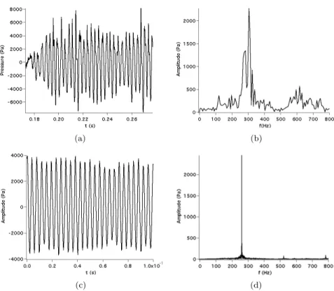
Figs. 7(a) and (c) show pressure time signals recorded during the simulation at the pressure probe 4 and compares these results to measurements obtained at Twente. Figs. 7(b) and (d) show associated Fourier transforms. In the LES data which contains all results including the instability growth and LCO, pressure oscillations grow in time until they saturate. The spectra of the signals show a dominant peak at f = 305 Hz and a secondary peak at f = 617 Hz. Experimental results (Figs. 7(b) and (d)) correspond only to LCO. They exhibit mainly one mode, at 261 Hz with an amplitude (4000 Pa) comparable to the LES results. The frequency difference between experiments (261 Hz) and LES (f = 305 Hz) frequency is due to the fact that the temperatures predicted along the combustor are ∼ 250 K higher than the ones measured experimentally. This is due to the absence of radiation models in the LES and probably to an insufficient convective transfer at the walls. Despite this difference, LES captures both the frequency and the amplitude of the first mode appearing in the LCO. The second mode predicted by LES at f = 617 Hz is very weak in the experimental results.
Having computed and measured experimentally a LCO containing two frequencies (305 and 617 Hz) is a first interesting result. The next question is to know where these modes come from. The combination of spectral analysis of LES results and acoustic computation with AVSP allows to identify the nature of the two unstable modes observed in Fig. 7: they are acoustic modes of the experimental set up. To demonstrate this, a collection of instantaneous solutions was generated and the Power Spectral Density (PSD) of the pressure field was calculated for the two peak frequencies of the limit cycle. Fig. 8 shows longitudinal profiles along the combustor of the mode shapes given by LES. It also compares this structure with the computation of acoustic modes performed with AVSP. AVSP was used to compute the modes of the complete combustor: the sound speed field for this computation was given by the average LES data. No active flame effect was included. AVSP predicts longitudinal modes at 186 Hz (mode 1), 337 Hz (mode 2), 570 Hz (mode 3) (Table 3). The 186 Hz mode is not observed in the LES. The 305 Hz mode observed in the LES has a structure which is very close to the second acoustic mode computed by AVSP. The 617 Hz mode obtained in the LES is close to the third acoustic mode and exhibits a node before the wedge (x = 0.1 m) and a second node in the chamber (x = 0.52 m). The slight discrepancies between the LES and the acoustic modes may be due to the treatment of the burner outlet at x = 1.05 m but the agreement in terms of frequencies and mode shapes confirms that the combustor resonates on the second and third acoustic modes of the whole set up and that LES and acoustic analysis match well.
(a)
(b)
(c)
(d)
(e)
Figure 6. Instantaneous temperature fields and reaction rate isocontours of simulation 1.
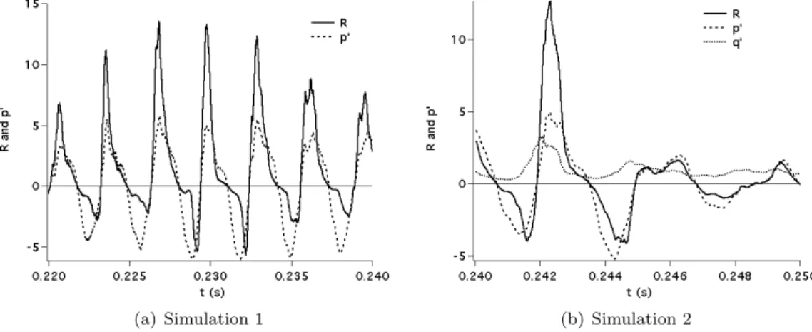
Fig. 9(a) shows pressure fluctuations p′ at probe 4 (expressed as a percentage of the mean pressure)
and a volume-averaged Rayleigh parameter R, calculated as R (t) = RV p′q′dV, where V is the volume
of the domain and q′ is a non-dimensional reaction rate normalized by its mean value. The Rayleigh
criterion is one measurement of the coupling between pressure and heat release oscillations [21,22,23]. It is positive when energy is fed into the acoustic field and viceversa. Here, R is positive most of the time:
(a) (b)
(c) (d)
Figure 7. Pressure signals at probe 4 (Fig. 2(a)). Left (a) and (c) : time signals. Right: (b) and (d): FFT. Top: LES (simulation 1), Bottom: Twente experiment. The LES data contains the initial growth phase from 0.18 to 0.22 ms. The experimental data corresponds only to the limit cycle variations.
Table 3
Acoustic eigenfrequencies of the burner given by acoustic analysis (AVSP).
Order of the mode Frequency (Hz)
1 185.5
2 336.7
3 570.2
there is a net energy transfer from combustion to the acoustic field so that the thermo-acoustic instability is self-sustained.
3.3. LES 2: stable case
Figs. 10(a) and 10(b) show instantaneous temperature fields and reaction rate isocontours corresponding to simulation 2. As the flow rate is increased, the hot gases trapped in the CORZ (corner recirculation zones) are blown away and the flame is not able to stabilize on the single CRZ (central recirculation zone) created by the wedge: fresh gases flow further downstream before burning, increasing the flame length as seen in Fig. 11. Heat release is distributed along a longer region and the energy transfer to the acoustic field is less effective, leading to the suppression of the thermo-acoustic instability.
Fig. 9(b) shows the temporal evolution of the Rayleigh parameter R and normalized pressure fluc-tuations for simulation 2. R is negative during a long time, showing that heat release is still ocurring
(a) (b)
Figure 8. Longitudinal profiles along the combustor of the normalized pressure fluctuations. Dashed line: spectral analysis of the LES data of Simulation 1 during the LCO. Solid line: acoustic code predictions (AVSP).
(a) Simulation 1 (b) Simulation 2
Figure 9. Rayleigh parameter and relative pressure fluctuation time signals of simulations 1 (left) and 2 (right).
(a)
(b)
(a) Simulation 1.
(b) Simulation 2.
Figure 11. Comparison of mean heat release rate fields between simulations 1 and 2 showing the difference in flame length.
when pressure is decreasing. This results in a reverse energy transfer from the acoustic field, so that the thermo-acoustic instability dies out, as mentioned before. As a result, LES predicts that the flow is stable, in agreement with experimental data. No spectra are presented here since only low-amplitude broadband noise was recorded, both in the LES and in the experiment.
4. Conclusions
LES and acoustic analysis of a lean, partially premixed, methane/air burner were performed for two operating points, and results were compared with experimental data obtained at Twente:
– Both stable and unstable behaviours of the burner, depending on its operating point, were successfully predicted by the LES.
– More than one acoustic mode can be excited at the same time. In the present study, the LCO seems to be a combination of the second and third acoustic modes of the complete experimental set up. – The aerodynamics of the gases within the burner control the stability of the combustor. Experimental
and numerical experiments show a transition to stability when the air inlet mass flow rate is increased beyond a certain threshold, because the flame is not stabilized by the corner recirculation zones. – Combustion driven thermo-acoustic instabilities can be predicted using modern LES tools, thereby
predicting and avoiding the appearance of thermo-acoustic instabilities in industrial combustion devices at an early design stage, reducing costs and time to market.
Acknowledgements
The authors gratefully acknowledge the financial support by the European Commission, within the Marie Curie Actions - Initial Training Networks, under call FP7-PEOPLE-2007-1-1-ITN, LIMOUSINE project with number 214905.
References
[1] Ann P. Dowling. The challenges of lean premixed combustion. Proc. International Gas Turbine Congress, 2003. [2] T. Lieuwen and V. Yang. Combustion instabilities in gas turbine engines. operational experience, fundamental
mechanisms and modeling. In Prog. in Astronautics and Aeronautics AIAA, volume 210, 2005. [3] L. Rayleigh. The explanation of certain acoustic phenomena. Nature, July 18:319–321, 1878.
[4] W. Meier, P. Weigand, X.R. Duan, and R. Giezendanner-Thoben. Detailed characterization of the dynamics of thermoacoustic pulsations in a lean premixed swirl flame. Combust. Flame , 150(1-2):2–26, 2007.
[5] J.D. Buckmaster. Edge-flames. Prog. Energy Comb. Sci. , 28(5):435–475, 2002.
[6] S. Ghosal and L. Vervisch. Theoretical and numerical investigation of a symmetrical triple flame using a parabolic flame type approximation. J. Fluid Mech. , 415:227–260, 2000.
[7] C. Jimenez and B. Cuenot. DNS study of stabilisation of turbulent triple flames by hot gases. Proc. of the Combustion
Institute, 31(1):1649–1656, 2007.
[8] S. Roux, G. Lartigue, T. Poinsot, U. Meier, and C. B´erat. Studies of mean and unsteady flow in a swirled combustor using experiments, acoustic analysis and large eddy simulations. Combust. Flame , 141:40–54, 2005.
[9] F. di Mare, W. Jones, and K. Menzies. Large-eddy simulation of a model gas turbine combustor. Combust. Flame , 137:278–294, 2004.
[10] P. Schmitt, T. Poinsot, B. Schuermans, and K. P. Geigle. Large-eddy simulation and experimental study of heat transfer, nitric oxide emissions and combustion instability in a swirled turbulent high-pressure burner. J. Fluid Mech. , 570:17–46, 2007.
[11] V. Moureau, P. Domingo, and L. Vervisch. From large-eddy simulation to direct numerical simulation of a lean premixed swirl flame: Filtered laminar flame-pdf modeling. Combust. Flame , in press, 2011.
[12] CERFACS. AVBP Handbook - http://cerfacs.fr/∼ avbp/AVBP V5.X/HANDBOOK. CERFACS, 2009. [13] P. D. Lax and B. Wendroff. Systems of conservation laws. Commun. Pure Appl. Math. , 13:217–237, 1960.
[14] J. Smagorinsky. General circulation experiments with the primitive equations: 1. the basic experiment. Mon. Weather
Rev. , 91:99–164, 1963.
[15] F. Charlette, D. Veynante, and C. Meneveau. A power-law wrinkling model for LES of premixed turbulent combustion: Part i - non-dynamic formulation and initial tests. Combust. Flame , 131:159–180, 2002.
[16] B. Franzelli, E. Riber, L. Gicquel, and T. Poinsot. Large-eddy simulation of combustion instabilities in a lean partially premixed swirled flame. Accepted for publication with minor revisions in Combustion and Flame, 2011.
[17] T. Poinsot and S. Lele. Boundary conditions for direct simulations of compressible viscous flows. J. Comput. Phys. , 101(1):104–129, 1992.
[18] L. Benoit and F. Nicoud. Numerical assessment of thermo-acoustic instabilities in gas turbines. Int. J. Numer. Meth.
Fluids , 47(8-9):849–855, 2005.
[19] F. Nicoud and K. Wieczorek. About the zero mach number assumption in the calculation of thermoacoustic instabilities.
Int. J. Spray. Comb. Dynamics, 1:67–112, 2009.
[20] Y. Huang and V. Yang. Bifurcation of flame structure in a lean premixed swirl-stabilized combustor: Transition from stable to unstable flame. Combust. Flame , 136:383–389, 2004.
[21] L. Rayleigh. On the theory of resonance. Phil. Trans. R. Soc. Lond., 161:77–118, 1870.
[22] D. Durox, T. Schuller, N. Noiray, A.L. Birbaud, and S. Candel. Rayleigh criterion and acoustic energy balance in unconfined self-sustained oscillating flames. Combust. Flame , 155(3):416–429, 2008.
[23] F. Nicoud and T. Poinsot. Thermoacoustic instabilities: should the rayleigh criterion be extended to include entropy changes ? Combust. Flame , 142:153–159, 2005.
![Figure 1. Left: schematic driving and damping amplitudes dependence on the instability amplitude and the resulting limit cycle amplitude A LC , from Lieuwen [2]](https://thumb-eu.123doks.com/thumbv2/123doknet/14308252.494980/5.892.107.765.230.386/schematic-amplitudes-dependence-instability-amplitude-resulting-amplitude-lieuwen.webp)