HAL Id: hal-02325692
https://hal.archives-ouvertes.fr/hal-02325692
Submitted on 23 Oct 2019HAL is a multi-disciplinary open access archive for the deposit and dissemination of sci-entific research documents, whether they are pub-lished or not. The documents may come from teaching and research institutions in France or abroad, or from public or private research centers.
L’archive ouverte pluridisciplinaire HAL, est destinée au dépôt et à la diffusion de documents scientifiques de niveau recherche, publiés ou non, émanant des établissements d’enseignement et de recherche français ou étrangers, des laboratoires publics ou privés.
Effects of impurities on graphite shape during
solidification of spheroidal graphite cast ions
Jacques Lacaze, Damien Connétable, Manuel Castro de Roman
To cite this version:
Jacques Lacaze, Damien Connétable, Manuel Castro de Roman. Effects of impurities on graphite shape during solidification of spheroidal graphite cast ions. Materialia, Elsevier, 2019, 8, pp.100471. �10.1016/j.mtla.2019.100471�. �hal-02325692�
1 Effects of impurities on graphite shape during solidification of spheroidal graphite cast ions
Jacques Lacaze1, Damien Connétable1, Manuel Jesus Castro de Roman2
Corresponding author : JL, e-mail: jacques.lacaze@ensiacet.fr, tel.: 33-5-34323415
1 - CIRIMAT, Université de Toulouse, ENSIACET, CS 44352, 31030 Toulouse cedex 4, France 2 – CINVESTAV Saltillo, Av. Industria Metalúrgica 1062, Parque Industrial Saltillo-Ramos Arizpe, Ramos Arizpe, Coahuila, Mexico, 25900
Abstract
Since the discovery that magnesium and cerium (and more generally rare earths) added at low level to cast iron melts lead to spherodized graphite, it is known that some other elements are detrimental even when present as traces. In all practicality, it has soon been recognized that adding rare earths to the melt helps counteracting the effect of these
detrimental elements. Accordingly, only few works have been devoted to studying the effect of trace elements in melts without any rare earths. This is the first aim of the present work to review those studies as they contain the material to understand the mechanism for spheroidal graphite degeneracy.
From this review, three type of degeneracies have been defined which show up when the critical level of any particular element is exceeded. These results are then discussed to show that all degeneracies certainly proceed in the same way. To substantiate this discussion, the growth of compacted graphite as obtained by low level treatment of cast iron melt with magnesium is also presented. Finally, a mechanism is suggested for describing the action of trace elements on spheroidal graphite degeneracy. This mechanism is partly substantiated by first-principles calculations which showed that all elements can strongly adsorb on the prismatic planes which are the planes on which carbon atoms add on during graphite growth.
Keywords: cast iron, solidification microstructure, graphite morphology, graphite
2 Introduction
Understanding growth of spheroidal graphite remains a challenge for both geologists [1] and metallurgists [2]. As a matter of fact, graphite spheroids present structural characteristics which are unique and are definitely not tackled by simulation at meso-scale such as phase field approach, see e.g. the extensive work on spherulite growth performed by Granazy et al. [3]. For metallurgists, an even more fascinating curiosity is the capability of low-level and trace elements to affect spheroidal growth and to lead to various shape changes, being them expected or unwanted.
In the world of metallurgy, spheroidal graphite irons is a relatively new foundry material dating back to the patent by Millis et al. in 1949 [4], though various previous historical records have been reported [5]. The negative effect of trace elements on graphite nodularity was already mentioned in the patent but it was very soon realized that adding rare earths (RE) would offset the problem in most cases [6]. In practice, the classical magnesium
treatment for spheroidizing cast iron melts is thus reinforced by addition of RE. Accordingly, many works have been devoted at optimizing the amount of RE to be added to counteract the presence of impurities, and much less have been concerned with the description of the impurity effect without RE addition, i.e. concerned with describing and understanding this effect.
The impurities listed in the patent [4] are As, Bi, Pb, Sb, Se, Sn and Te, and it is worth stressing that most of them are also harmful to non-spheroidized lamellar graphite iron melts as reviewed by Reynaud [7]. In an extensive study aimed at controlling the charges for melt preparation, Thielemann [8] proposed the following quality index Sb for spheroidal
graphite cast irons where Al and Ti appear but not Se and Te which were not considered:
Ti Sn Sb Pb Bi As Al b 1.6 w 2.0 w 370 w 290 w 5.0 w 2.3 w 4.4 w S = ⋅ + ⋅ + ⋅ + ⋅ + ⋅ + ⋅ + ⋅ (1)
in which wi is the weight fraction of i element in the charge used for preparing the melt. This
quality index has been obtained with spheroidal graphite cast irons containing 0.04 to 0.08 wt.% Mg that were cast with wall thickness in between 8 and 45 mm. When Sb is lower than
1 no action is necessary while if it is higher RE should be added to avoid spheroidal graphite degeneracy.
3
What is seen in the Thielemann’s factor and which reflects foundry practice is that bismuth and lead have a much higher coefficient than the other poisoning elements. This would not change if their content was expressed in mole fraction and this difference suggests that the mechanism of their action may differ in some way from that of the other elements. It was the aim of the present work to rationalize experimental observations and characterizations to suggest a mechanism for spheroidal graphite degeneracy appearing during solidification. It was thought of interest to first consider the various "standard" forms of graphite in lamellar, spheroidal and compacted graphite cast irons, including works on synthetic Fe-C-(Si) and Ni-C alloys. Then, a review of metallographic observations of graphite degeneracy induced by impurities and low-level additions in RE-free spheroidal graphite irons is presented. Finally, a number of deductions are made and discussed, and an attempt to rationalize the role of these elements with the help of first principles calculations is carried out.
Lamellar, spheroidal and compacted graphite
Without any special attention, a reasonably clean charge to prepare a cast iron melt consists of a Fe-C-Si alloy with possibly some alloying metallic elements (Cr, Cu, Mn, ..) and low-level amounts of oxygen and sulphur. Upon solidification in the stable system, this will give rise to flake graphite at low cooling rate and to undercooled graphite at high cooling rate. The transition is related to increased branching of the flakes in undercooled graphite as compared to lamellar graphite which can be accomplished by twinning [9, 10].
When studied by directional solidification experiments, the transition has been sometimes reported to be abrupt in terms of characteristic inter-lamellar distance [9], while for others both morphologies can coexist in a range of growth conditions [11]. From cooling curves and microstructure recorded on castings of various sizes, Thorgrimsson [12] found that the transition occurs at an eutectic undercooling ∆T of about 10°C, a value in agreement with later estimate by Park and Verhoeven [10]. In figure 1, the two lower curves illustrate schematically that the eutectic undercooling of these two eutectics increases with growth rate (e.g., as imposed by directional solidification). It is there assumed that the evolving microstructure at given growth rate is the one having the lowest undercooling, or
4
equivalently the highest growth temperature [11]. The micrographs along these curves illustrate that the spacing between graphite flakes is much smaller in undercooled graphite than in lamellar graphite.
Figure 1 – Change of eutectic undercooling ∆T versus growth rate for the four types of lamellar graphite coupled eutectics. Micrographs are from Ruth and Turpin [13] for plate graphite (a), Lux et al. [14] for coral graphite (b), and Day [15] for flake (c) and undercooled (d) graphite.
If the melt is purified, i.e. that oxygen and sulphur are decreased to very low levels, flake graphite is changed to plate-like at low growth rates in Fe-C-(Si) alloys [13, 16, 17] and in Ni-C alloys as well [18, 19, 20]. This graphite shape differs from lamellar graphite by showing little branching, having straight outer boundaries and even thickness see figures 1 and 2. With increased growth rate, the plate-like graphite changes to coral graphite which differs from
5
forms of graphite in cast irons were looked for, Campomanes and Groller [21] found that addition of Zr which is a strong deoxidiser changed lamellar graphite to coral graphite in castings made from cast irons with very low level of sulphur (less than 20 ppm). At a slightly higher level of S of 60 ppm, Liu and Loper [22] observed a more complex series of transitions with decreasing cooling rate in a wedge casting: from spheroidal to compacted, then to coral and then to undercooled graphite. This suggests that the maximum level of S for having coral graphite instead of undercooled graphite increases with increase in the cooling rate.
Coral graphite has sometimes been described as fibre-like [17]; it resembles a rod-like eutectic but is highly branched and thus appears irregularly distributed [10]. Considering pure enough melts, there must be a critical growth rate at which plate-like graphite is replaced by coral graphite as suggested by the two upper curves in figure 1. In this figure, the relative positioning of the curves for plate-like and flake graphite in terms of
undercooling relies on the result by Lux and Kurz [17] who showed sulphur decreases the growth temperature of the austenite-graphite eutectic. This may be due to both or either: i) sulphur being rejected by austenite at the two-phase solidification front decreases the local reference eutectic temperature [23, 24]; ii) an intrinsic effect of sulphur on the growth mechanism of graphite or of the eutectic cells [25].
What finally suggests figure 1 is that sulphur and oxygen do not affect graphite growth in the same way. This goes in line with the observation by secondary ion mass spectroscopy (SIMS) [26] and Auger spectroscopy [10] that sulphur adsorbs on basal planes and oxygen on prismatic planes of graphite.
All four structures described above result from coupled austenite/graphite eutectic growth. In the case of synthetic hypereutectic Fe-C, Fe-C-Si or Ni-C alloys, primary solidification of graphite gives also rise to plate-like lamellae [20, 27]. Increasing the cooling rate leads to simultaneous growth of primary plate-like lamellae and spheroids as illustrated in figure 2. Increasing further the cooling rate may eliminate the lamellae leaving only spheroids [18, 20]. This simple schematic of the effect of cooling rate on graphite shape in pure alloys is generally accepted. In one investigation using directional solidification, growth of coral graphite has been reported and a transition from coral to spheroidal growth has been observed [28]. Even more significant, Dhindaw and Verhoeven [28] noticed the suppression of spheroidal graphite in outgassed melts made from highly pure materials. The authors
6
suspected this suppression to be due to the disappearance of any graphite nucleation substrates. This means that coupled growth of graphite and austenite would be preferred even at high eutectic undercooling in pure iron melts, unless spheroidal graphite may nucleate ahead of the coupled solidification front. Finally, it should be mentioned that Muhammad and Fredriksson [29] have recently reported primary precipitation of rod-like graphite with more or less circular section as coral graphite1.
Figure 2 – Graphite plates and spheroids in a rapidly solidified pure Fe-C-Si alloy [30]. Alloy with 2.81 wt.% carbon and 9.91 wt.% silicon.
In all practicality, adding an inoculant to a cast iron melt eases solidification in the stable system, while a proper spheroidizing treatment (with magnesium or magnesium and RE) triggers spheroidal growth instead of lamellar growth. It is worth mentioning here that compacted graphite is obtained most commonly with low level addition of magnesium, though other methods exist [31, 32, 33]. If the first effect of magnesium is to tight oxygen and sulphur as generally accepted, then considering again figure 1 is of interest. Indeed, Nieswaag and Zuithoff [9] have shown that decreasing the sulphur level in Fe-C-(Si)-S alloys does increase the critical growth rate for the transition between lamellar and undercooled graphite (their figure 3), see the lower vertical interrupted arrow in figure 1. Similarly, Park and Verhoeven [10] have noticed that decreasing the oxygen level in the melt increases the
1 In a private discussion during the conference EUROMAT-2019, Muhammad clarified that the wording
7
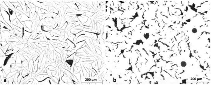
critical velocity for plate-like to coral graphite transition, see the upper vertical interrupted arrow. Hence, by removing oxygen and sulphur, low level addition of magnesium made to a cast iron melt decreases the branching capability of graphite. This is in fact what is observed in figure 3 where are compared the microstructures of a compacted graphite and of a lamellar graphite cast irons that have been solidified in the same conditions (thermal cup) [34]. It is seen that the graphite lamella are much coarser and much less branched in compacted graphite than in lamellar graphite material. This peculiar shape has been compared to worms but it has been demonstrated that these are 2D sections of interconnected wavy and irregular lamellas [35, 36, 37, 38].
Figure 3 – Comparison of the microstructure of lamellar (a) and compacted (b) graphite cast irons solidified in a thermal cup. Courtesy of IK4-Azterlan.
It is well accepted that plate-like, flake and undercooled graphite do grow along the prismatic direction. The structure of coral graphite has been investigated by Lux et al. [14, 39] and by Park and Verhoeven [10]. By transmission electron microscopy, Lux et al. [14] established that graphite layers in coral graphite have the [0002] direction perpendicular to the surface of the branches, meaning coral graphite grows also in the prismatic direction. However, both studies reported that coral graphite contains much more defects and orientation changes than any of the other graphite forms. There is unfortunately not much detailed work reported on the mechanism of graphite branching. In pure Ni-C alloy, Double and Hellawell [19] demonstrated that plates of graphite grow with a preferred <1120>
8
direction and branch in the plane of the graphite sheets as schematically illustrated with Figure 4-a. These plates are made of a stack of perfect crystals typically 100 nm in thickness each that may be rotated between each other following so-called coincident stacking with angles of about 13, 22 and 28 deg. They also present twinning across
[ ]
1121 reflexion plane which leads to bending of the basal plane through 20°45’ with a <1100> rotation axis. However, these twins do not appear to develop out of the sheet plane in plate-like graphite while they do in flake and undercooled graphite [10], see figure 4-b. These observations suggest that different branching mechanisms operate during plate-like and flake-like or undercooled graphite growth, i.e. depending on the fact that sulphur is present or not. Coral graphite shows both an enhanced branching mechanism [14, 39] and a modification of the growth shape [10, 19, 29] as in the case of silicon in Al-Si eutectic [40, 41] after so-called modification with strontium.As will be seen in the following, the above description of usual graphite shapes in cast irons is instrumental for understanding spheroidal graphite degeneracy. Indeed, compacted graphite may be seen as one such degenerate form of spheroidal graphite.
Figure 4 – The branching mechanisms of graphite [9]: in-plane branching (a), branching by twisting (b), and combination of both (c).
9 Effect of selected impurities on spheroidal growth of graphite
As seen in the previous sections, spheroidal cast irons are Fe-C-Si alloys with addition of a spheroidizer such as magnesium or a mix of magnesium and RE. They also contain low levels of oxygen and sulphur, as well as some gases (hydrogen and nitrogen) dissolved in the liquid, and impurities most often coming from recycling. Because RE are prone to tight most of the elements as compounds, the present review was limited to observations on RE-free cast irons with the hope that some clear trends would show up. Although recent reviews are available [7, 42], this is quite old and scarce literature. Further, only additions within the ranges found in practice have been considered because higher additions may lead to other kinds of graphite degeneracy [43]. Some detailed information has been found regarding Al, Bi, Pb, Sb and Ti, to which it was considered adequate to add Mg. Moreover, only single additions were considered though their possible interactions are of a definite practical importance.
In many of the reports, emphasis is put on the effect of cooling rate on the type of graphite degeneracy observed. This has been accounted for here by differentiating, whenever appropriate, small- and heavy-section castings corresponding to high and low cooling rates, respectively. Figure 5 illustrates this cooling-rate effect in the case of a cast iron doped with titanium [44]. In a rod 25 mm in diameter, titanium leads to worm-like graphite (figure 5-a) while in a plate of 72 mm in thickness an extended network of mesh graphite is observed (figure 5-b). Note also the presence of degenerate spheroids and of spiky graphite at the bottom of figure 5-b. A similar effect of cooling rate has been reported for titanium also by Gilbert [45]. It has been stressed by Hecht [44], and this is clearly seen in figure 5, that the degeneracies are physically connected to spheroids.
In Mg-treated melt, aluminium gives rise first to the formation of spheroids and then, with the progress of solidification, to worms as in compacted graphite iron [46]. The observation of the micrographs in the work by Fargues and Margerie [47] on a 2 wt.% Al and 2 wt.% Si spheroidal graphite cast iron shows that the worms start from the nodules, i.e. they are not nucleated in the liquid.
10
Figure 5 – Optical micrographs of a spheroidal graphite cast iron doped with titanium: a) with 0.16 wt.% Ti, cast as a 25 mm in diameter rod; and b) with 0.10-0.11 wt.% Ti cast as a 72 mm thick plate (b) [44].
With 0.02 wt.% of antimony added to a cast iron melt, Gilbert [45] reports the formation of spiky or lamellar protuberances until all spheroids have disappeared at 0.09 wt.% Sb in 45 mm keel-blocks. The graphite aggregates however maintain a quite compact shape, see figure 6-a, hence the crab-like denomination. Similar aggregates have been reported by Bates and Wallace [48] and Tybulczuck et al. [49] as a result of Sb addition. Interestingly enough, very low level additions of antimony and arsenic give highly spheroidal graphite particles [49, 50] which may still be present when crab-like graphite starts appearing [45]. It is totally unknown if this action is a direct one, i.e. very low level of these elements favours spheroidal shape, or an indirect one where these elements tight other detrimental trace elements. Finally, as for the case of antimony and arsenic, excess of tin leads to crab-like graphite degeneracy according to Thielemann [8].
Appropriate magnesium treatment relates to 0.04-0.08 wt.% residual magnesium, with 0.02-0.03 wt.% free magnesium left dissolved in the melt [49, 52]. In case of over-treatment, namely for 0.10 wt.% Mg and over, spheroidal graphite degeneracy is observed [8, 51] that is much alike that obtained with antimony, see figure 6-b. Sometimes, degenerate graphite due to magnesium appears only in intercellular areas where it takes a spiky or lacy shape [49, 51]. However, the connection of these intercellular precipitates with graphite spheroids
11
may be again observed [51]. It is worth mentioning that other spheroidizers, namely rare earth elements including yttrium, lead also to crab-like graphite when added above a critical level [53].
Figure 6 – Optical micrograph of spheroidal graphite cast irons: (a) doped with 0.11 wt.% antimony [45], etched with Picral; (b) over-treated with magnesium [51].
Lead and bismuth lead to the same kind of mesh graphite which is illustrated in figure 7. Gilbert [45] classified it as coarse lamellar graphite, thus differentiating this shape from the more compact crab-like aggregates generated by antimony addition (see figure 6-a). In a recent work, Tonn et al. [54] have demonstrated the physical connection between spheroids and intercellular graphite in a cast iron doped with lead. In one case, a crab-like structure has been reported in a cast iron containing 50-60 ppm of bismuth and cast as a 30 mm rod [55]. Thielemann [8] has observed similarly that lead leads to crab-like graphite at less than 20 ppm which changes to mesh graphite at higher level. This strongly suggests a continuum exists between all degenerate forms considered in the present work, namely worms, crab-like and mesh graphite. Further, and though it would be of interest to substantiate this with appropriate observations, the shape of these degeneracies leads thinking they mainly grow along the prismatic direction of graphite as does flake graphite.
12
Figure 7 – Micrographs showing: (a) the effect of 26 ppm of bismuth [42, 49], slow cooling rate; (b) the effect of lead on spheroidal graphite iron with 70 ppm of lead [7, 42],
intermediate cooling rate (the scale was not reported but the diameter of the nodules is thought to be 30-40 µm).
Discussion
When magnesium is added to cast iron melts, it first tights oxygen and sulphur, and the remaining which is called free-magnesium may adsorb freely on graphite [25, 52]. While the overall or apparent growth direction of spheroidal graphite is along the basal plane
direction, the growth mechanism involves carbon atoms attaching to the prismatic planes as previously discussed [56]. It has been suggested that spheroidizers adsorb on these prismatic planes [8, 43, 57], and this has been accepted on the basis of laboratory studies on Fe-C-Ce alloys [27]. However, when magnesium is added in excess, typically above 0.08 wt.%, protuberances start growing out of nodules which are much alike those seen with antimony (figure 6). This strongly suggests that magnesium atoms are now blocking the advance of the growth steps along the surface of the spheroids and trigger growth of protuberances.
Note that the above description does not give a definite explanation to spheroidal growth. The question here is rather to clarify if this schematic is of any help to understand the role of impurities on degeneracy of spheroidal growth. From the previous section, addition of
so-13
called poisoning elements above a critical level leads to the appearance of spikes at the surface of the spheroids which then develop as worms. The resulting microstructure is reminiscent from that of compacted graphite. In case of slow cooling, this crab-like or worm-like morphology evolves in mesh graphite as is illustrated in figure 5-b for the case of
titanium. It is thus seen that there is a continuous evolution from crab-like to worms and then from worms to mesh graphite.
In the past, a number of theoretical attempts to rationalize the effect of low level elements on spheroidal graphite degeneracies were carried out. In his outstanding review, Lux [25] mentioned attempts done considering electronic distribution of the elements and metal– non-metal binding energies. These approaches showed however quite limited application and this suggested resorting to first principle calculations. Before discussing such
calculations, it is however of interest to note that the elements mentioned in the present work show an interesting sorting when considering their difference in electronegativity with carbon, ∆EN, using Pauling's scale. This is done in figure 8 where the greyed area denotes the
range of values where non-polar bonds are expected. In this area are found the two
elements that are known to adsorb on basal planes, sulphur [10] and tellurium [58]. Oxygen has a strong (negative) value and is known to adsorb on prismatic planes [26]. Figure 8 thus suggests that all elements but sulphur and tellurium will preferentially adsorb to the
prismatic planes as does oxygen, with the exception of antimony which is just at the limit and may well go equally on both sites. Note that for elements with high atomic weight, Bi, Pb and Sb, the effect of van der Waals forces should have to be considered in addition to covalent bonds.
14
Figure 8 – Difference in electronegativity between carbon and various elements having an effect on graphite growth in cast irons.
There have been numerous density functional theory (DFT) calculations on the interaction between foreign atoms and graphite layers, but only a few dealing explicitly with cast irons [29, 59]. In the annex are presented new DFT calculations reporting values of adsorption energy and of the stable distance between a foreign atom and graphite. These calculations have been performed for adsorption on basal and prismatic planes. In this later case, calculations were carried out for two configurations, the so-called arm-chair and zig-zag configurations. The elements considered are C itself, and Al, Ca, Fe, Mg, O, S, Sb, Sn, Te and Ti.
These calculations show that the adsorption energy of all these elements is strongly negative on the zig-zag position. For the arm-chair configuration, this adsorption energy is still
significantly negative but with values often half those for the zig-zag position. For the basal planes, the calculated adsorption energy is only slightly negative, being even slightly positive for Sb. It could thus be concluded that any element could adsorb on the basal planes - apart
15
for Sb - but the calculations predict this will much more likely happen on the prismatic planes.
These calculations thus support the suggestion made above that foreign elements add up on the prismatic planes. S and Te appear however to be exception in that DFT calculations do not predict their preferential adsorption on the basal planes. As a matter of fact, DFT calculations are conducted for graphite in vacuum, not considering the metallic matrix with which graphite is in contact in cast irons. S and Te are in fact particular elements – located in the same column in the Mendeleyev table - which are known to easily form associates with Fe, namely FeS and FeTe respectively. Such associates were already considered by
Kozakevitch et al. [60] to explain the role of sulphur in cast iron melts. They have been also seen to be necessary for appropriate thermodynamic description of the S [61, 62] and Fe-Te [63] systems. This suggests that the existence of these associates is the fundamental reason for S and Te to preferentially adsorb on basal planes. Molecular dynamics could certainly overtake the limits of DFT calculations and one attempt has been reported recently [64] dealing with the effect of O on iron/graphite interfacial behaviour.
The effect of any added atom on the prismatic planes should be proportional to the area it occupies and to the number of electrons on its outermost shells. Further, it was thought that the effectiveness of an added element would decrease when the difference in adsorption
energy with that of carbon increases. Accordingly, the quantity
( )
) C ( E ) i ( E ne r r ad ad i 2 C i − ⋅ = ∆ −
was evaluated, where ri is the ionic radius of i atom,
( )
ne i− is the number of electrons on the
outer shells of i atom and Ead(i) is the adsorption energy of i atom. This quantity is plotted
versus the Thielemenann’s factor Sb (eq. 1) in figure 9, where the adsorption energy of Bi
and Pb has been set to that of Te (Table A1). Owing to the fact that Mg and Ca are
spheroidizers, they could be attributed a low value of 1 and 2 respectively in the expression of Sb. It is seen in figure 9 a good correlation between ∆ and Sb which stresses the
importance of the size effect and the correlated number of outer electrons on the poisoning effectiveness of an element.
16
Figure 9 – Relation between Thielemann’s factor Sb and the quantity ∆ which characterizes
adsorption of i atoms on graphite.
Finally, a schematic for spheroidal graphite degeneracy may be suggested on the basis of the growth model previously developed [56]. This model assumes that growth of graphite
spheroids proceeds by nucleation of new growth blocks at the outer surface of the spheroids which then grow along that surface, see Figure 10-a. This process works well as long as there is just enough Mg for limiting the lateral extension to the surface of the spheroid by
adsorbing on the prismatic planes. In case there is not enough Mg, graphite protuberances may develop in a direction tangential to the surface, see figure 10-b. This is thought to be the process by which compacted graphite develops out from spheroidal graphite. In the case foreign elements adsorb on the prismatic planes together with Mg, the growth may
eventually be blocked in the prismatic direction, forcing graphite to protrude away from the spheroid surface, see figure 10-c, as do spikes described in the previous section.
17
Figure 10 – Schematic of spheroidal growth of graphite following a 2D nucleation and growth model (a) where Mg atoms adsorb preferentially on the prismatic planes [56]. Formation of protuberances in case of too low Mg content (b) or of foreign element (red dots) adsorbing together with Mg on the prismatic planes (c).
18 Conclusion
Analysis of the literature on the effects of trace elements on spheroidal graphite degeneracy suggests that a continuum exists between worms, crab-like and mesh graphite. These
degeneracies certainly mainly grow along the prismatic direction of graphite as does flake graphite, though this claim should be substantiated by dedicated studies. Also, these degenerate graphite forms show little branching as does compacted graphite, in which case this has been correlated with the very low levels of S and O remaining in the melt. A
schematic for graphite degeneracy has been proposed that relies on adsorption of foreign atoms at the graphite surface.
Most of the impurities which are known to lead to degenerate forms of graphite during solidification of spheroidal graphite cast irons are also known to promote pearlite during the eutectoid transformation. As a matter of fact, the most usual reason for a pearlite promoter effect is the blocking of ferrite growth by hindrance of carbon transfer from the parent austenite to graphite. This suggests that the elements poisoning spheroidal graphite growth during solidification keep this capability at lower temperature when the iron-rich matrix has become solid.
In the future, molecular dynamic calculations should be preferred to DFT calculations which have been shown not to predict the preferential adsorption of S and Te on the basal planes of graphite. Further, it should be of first interest to investigate the interactions of foreign elements between each other during graphite growth within an iron-rich matrix. Owing to the prominent role of S and O, their interactions with the trace elements considered in this work are certainly worth of investigation.
Acknowledgments
19 Annex — Ab initio calculations
Calculations were performed using the VASP package [65]. The plane-wave basis projector augmented wave (PAW) method [66, 67] and the Perdew-Burke-Ernzerhof generalized gradient approximation of the exchange and correlation functional (PBE) [68] were employed in the framework of the density functional theory (DFT). To take into account Van-der-Waals interactions, the Tkatchenko-Scheffler method [69] with iterative Hirshfeld partitioning [70] was employed. Calculations were performed with spin effects and the plane-wave energy cut-off was set to 1000 eV.
Fine Monkhorst-Pack meshes [71] were used to sample the first Brillouin zone of the super-cells. To describe basal surfaces 72 carbon atoms were considered, i.e. 3×3 super-cells in the basal plane, and 2 cells in the perpendicular direction, z, meaning 10×10×1 k-meshes. To deal with so-called prismatic planes, two configurations were considered in the basal plane, the armchair and zigzag surfaces. For the armchair surface 80 carbon atoms were used to build 5×1×2 super-cells – with the vacuum along y axis -, meaning 10×1×20 k-meshes. The zigzag structure was composed of 2 graphene sheets and was 5 atomic planes thick (72 C atoms), meaning as well 10×1×20 k-meshes. A large vacuum was introduced in the super-cells, about 14 Å, to minimize interactions between surfaces.
The system was first optimized for the carbon atom positions and shape of the super-cells. Theoretical lattice parameters of graphite were thus found equal to 2.46 Å and 6.74 Å, which agree well with experimental values at 2.46 Å and 6.71 Å. First principles calculations were then carried out to study the possibility of adsorption on graphite of the following elements: C, Al, Ca, Fe, Mg, O, S, Sb, Sn, Te and Ti. This was done by adding one of these atoms to the system. On both basal and prismatic planes, different possible locations for adding this atom were considered as described below. To finally analyse the interaction of the added atom and graphite, we defined the adsorption energies, Ead, by:
Ead = Eo[graphite+X] - Eo[graphite] - Eo[Xat] (A-1)
where Eo corresponds to the DFT energies, with Eo[Xat] the energy of the isolated X atom,
Eo[graphite] and Eo[graphite+X] being the energy of the system before and after addition of
X, respectively. For all calculations, the distance dX-Gr between the added atom and the top
20
For the basal plane, four possible initial configurations of the added atom were considered which are shown with the two circles and two discs in Fig. A1. In most of the cases, the bridge (B) and hexagonal (H) positions indicated with discs were found most stable after relaxation. The only exception was Sn which was predicted most stable in top position, i.e. above one C atom. Ead and dX-Gr values are reported in table A1. All elements except the Sb
atom show a negative energy indicating the possibility for their adsorption. The calculated distance to the graphite plane in the case of Mg and Te is high in regard to other species which shows adsorption of these two elements would be very unlikely. Considering the distance to the graphite plane calculated for the elements that could adsorb, it is seen that the O atom is closer to the graphite than all other species. Most of the species are located near the surface, at a distance in the range 1.4 to 2.1 Å. Nevertheless, a simple discussion of adsorption energies and distances is not sufficient to explain why some species prefer to be adsorbed on basal plane. The results show that Fe is in strong competition with all species that can adsorb on the basal plane. Since Fe is the main component in the actual system, it should form Fe layers that prevent the adsorption of other species. Indeed, there is a strong affinity between Fe and C atoms. For instance, the S atom adsorbs further away and less strongly than the Fe atom. The present results would thus suggest that oxygen can adsorb easily on the basal plane while it would be more difficult to sulphur, which is however just opposite to experimental evidence.
Figure A1 — Added atom was initially located above the basal plane in four possible positions indicated with the two circles and two discs. The positions B and H refer to the most stable positions after relaxation. The hexagonal network of carbon atoms is depicted by the bonds represented with bold solid lines.
21
As depicted in Fig. A2, two possible positions A and B were considered for both the chair (Fig. A2-a) and zig-zag (Fig. A2-b) configurations in the case of the prismatic planes.
Figure A2 – Schematic of possible adsorption sites in the prismatic planes. The added atom (solid circles) was initially located in either of the two possible positions (A and B) ahead of the chair configuration (a) and of the zig-zag configuration (b).
The results of the calculations for the chair configuration are also reported in Table A1, which include the values of Ead and dX-Gr for both A and B positions, with the most stable
being shown in bold. In contrast to all other elements, calculation for oxygen led to a most stable position located near a C atom and denoted C in table A1, as displayed in Figure A3. These values of the energy are always more negative than those for the basal plane, indicating a possible preference for adsorption on the prismatic planes. This may be explained by the presence of pending bonds (sp orbitals) which favour the hybridization with foreign atoms. Here, oxygen and sulphur show the most negative adsorption energies and the shortest distances to the graphite plane, though the distance for oxygen is smaller than for sulphur.
22
Figure A3 – Position of the most stable added oxygen atom onto the chair configuration.
Calculations for the zig-zag configurations generally gave even higher adsorption energy than for the chair configurations as seen in Table A1. Again, the energies and distances for oxygen and sulphur appear highly favourable for adsorption of these elements on the prismatic plane. It can be noted that the position B, which involves a C-X double bond, is favoured in all cases except oxygen. This suggests that apart for the O atom, this position makes it possible to optimize interactions and thus to increase charge transfer. With regard to oxygen, the possibility of forming a O-C double bond as in the CO molecule seems to be at the origin of the high stability of the A configuration. The dO-Gr value was found at 1.23 Å
which is only slightly higher than the C-O distance at 1.1 Å in the CO molecule.
For both armchair and zig-zag configurations, it was found that the distance of the most stable location of the added atom is slightly larger than the ideal distance in the graphite network. This difference has to do with the size of the added atoms. The B position in armchair configuration leads to quite large bond length which may be further increased by the size effect. This certainly explains that the Ead values are significantly lower for the
armchair configurations than for the zig-zag ones. For this armchair configuration, the Ead
values are less negative for added elements than for carbon. On the contrary, it is worth noting that the Ead values are more negative for O and Ti than for C in the zig-zag
configuration, indicating that these elements may adsorb preferentially to carbon.
In the literature, there seems to be only one work which considered similarly all possible sites for adsorption on graphite. This is the work by Incze et al. [72] who studied the case of O adsorption. In this study, use was made of a slightly different functional (GGA-PW91) with
23
a very low value for convergence at 270 eV. However, the authors did not take into account magnetism and Van-der-Waals forces. To recover, the interlayer graphite spacing, they instead artificially modified the inter-plane distance of the graphite. However, their results are qualitatively equivalent to ours. On the basal plane, the stable site is the bridge site B as in this study, with an energy of -1.73 eV and a distance of 1.41 Å while we obtain an energy of -1.46 eV and a slightly shorter distance of 1.30 Å. As for the prismatic plane, they found that the configuration A for ZZ and B for armchair configurations are the most stable which is consistent with our results. The energies are nevertheless a little different, probably due to the functional approach used on the one hand and the low values of the convergence criterion they had used on the other.
24 References
[1] J.A. Jaszczak, Graphite: flat, fibrous and spherical, in Mesomolecules, G.D. Mendenhall and J.F. Liebman (Eds.), Chapman & Hall, 1995, pp. 161 – 180.
[2] D.M. Stefanescu, G. Alonso, P. Larranaga, E. de la Fuente, R. Suarez, Reexamination of crystal growth theory of graphite in iron-carbon alloys, Acta mater., 139, 2017, 109-121 [3] L. Granasy, T. Pusztai, G. Tegze, J.A. Warren, J.F. Douglas, Growth and form of spherulites, Physical Review E, 72, 2005, 011605
[4] K.D. Millis, A. P. Gagnebin, N. B. Pilling, Cast ferrous alloy, patent 2,485,760
[5] D.M. Stefanescu, A history of cast iron, ASM Handbook, Vol. 1A, Cast iron science and technology, 2017, 3-11
[6] H. Morrogh, Influence of some residual elements and their neutralization in magnesium-treated nodular cast iron, Trans. AFS, 60, 1952, 439-451
[7] A. Reynaud, Oligo-éléments et fontes, éditions ETIF, 2005
[8] T. Thielemann, Zur Wirkung von Spurennelementen im Gusseisen mit Kugelgraphit, Giessereitechnik, 16, 1970, 16-24, CTIF translation to French #T-4756
[9] H. Nieswaag, A.J. Zuithoff, The effect of S, P, Si and Al on the morphology and graphite structure of directionally solidified cast iron, in The metallurgy of cast iron, Georgi Ed., 1975, 327-351
[10] J.S. Park, J.D. Verhoeven, Transitions between type A flake, type D flake, and coral graphite eutectic structures in cast irons, Metall. Mater. Trans. A, 27A, 1996, 2740-2753 [11] M. Hillert, V.V. Subba Rao, Grey and white solidification of cast iron, ISI Pub., London, 110, 1968, 204-212
[12] J.T. Thorgrimsson, Effect of cooling rate on structure formation in cast iron castings, Licentiate thesis, Royal Institute of technology, Stockholm, 1986.
[13] J.C. Ruth, M. Turpin, Structures de solidification unidirectionnelle des eutectiques fer-carbone, Mém. Sci. Rev. Métall., 61, 1969, 633-640
[14] B. Lux, W. Bollmann, M. Grages, On the structure of graphite in pure Fe-C-Si alloys, Pract. Metall., 6, 1969, 530-535
[15] M.G. Day, Use of scanning electron microscopy to investigate aluminum/silicon and iron/graphite eutectic systems, J. of Metals, April, 1969, 31-34
[16] K.D. Lakeland, Directional solidification of iron-carbon, iron-carbon-silicon and nickel-carbon eutectic alloys, BCIRA J., 12, 1964, 634-650
[17] B. Lux, W. Kurz, Eutectic growth of iron-carbon-silicon and iron-carbon-silicon-sulphur alloys, in The solidification of metals, ISI Pub. 110, 1968, 193-203
25
[18] R.J. Brigham, G.R. Purdy, J.S. Kirkaldy, Unidirectional solidification of C, Ni-C and Fe-C-Si eutectics, Int. Conf. On Crystal Growth, 1966, 161-169
[19] D.D. Double, A. Hellawell, The structure of flake graphite in Ni-C eutectic alloy, Acta metall., 17, 1969, 1071-1083
[20] S. Amini, R. Abbaschian, Nucleation and growth kinetics of graphene layers from a molten phase, Carbon, 51, 2013, 110-123
[21] E. Campomanes, R. Groller, Production of cast iron containing intermediate forms of graphite, AFS Trans. 83, 1975, 55-62
[22] P.C. Liu, C.R. Loper, Scanning electron microcope study of the graphite morphology in cast iron, Scanning Elec. Micro. 1, 1980, 407-418
[23] K.D. Lakeland, Directional solidification of Fe-C eutectic alloys containing various percentages of sulphur, J. Austral. Inst. Met., 10, 1965, 55-63
[24] W. Kurz, discussion of the paper by Nieswaag and Zuithoff, in The metallurgy of cast iron, Georgi Ed., 1975, 353
[25] B. Lux, On the theory of nodular graphite formation in cast iron – Part I: experimental observations of spherulitic graphite formation during solidification of cast iron melts, AFS Cast Metals Research Journal, 8, 1972, 25-39
[26] S.E. Franklin, R.A. Stark, Further use of secondary ion mass spectrometry in the study of graphite morphology control in cast irons, in The physical metallurgy of cast iron, MRS symposia proceedings, 34, 1985, 25-35
[27] K. Theuwissen, J. Lacaze, L. Laffont, Structure of graphite precipitates in cast iron, Carbon, 96, 2016, 1120-1128
[28] B. Dhindaw, J.D. Verhoeven, Nodular graphite formation in vacuum melted high purity Fe-C-Si alloys, Metall. Trans. A, 11A, 1980, 1049-1057
[29] H. Muhammad Muhmond, H. Fredriksson, Relationship between the trace elements and graphite growth morphologies in cast iron, Metall. Mater. Trans. A, 45A, 2014, 6187-6199 [30] B. Vigneron, Thesis, University of Nancy, France, 1973
[31] E. Nechtelberger, H. Puhr, J.B. von Nesselrode, A. Nakayasu, Cast iron with vermicular graphite – State of the art. Development, production, properties, applications, Int. Foundry Congress, CIATF, 1982, 1-39
[32] M. Chisamera, I. Riposan, New methods to obtain coral graphite cast iron, Int. J. Metals Res., 11, 1999, 325-331
[33] M. Gorny, Cast iron: compacted graphite, Encyclopedia of Iron, Steel, and Their Alloys, Taylor & Francis, 2015, 718-734
26
[34] J. Lacaze, J. Sertucha, Some paradoxical observations about spheroidal graphite degeneracy, China Foundry, 15, 2018, 457-463
[35] Den Xijun, Zhu Peiyue, Liu Qifu, Structure and formation of vermicular graphite, Mat. Res. Soc. Symp. Proc., 34, 1985, 141-150.
[36] C. Chuang, D. Singh, P. Kenesei, J. Almer, J. Hryn, R. Huff, 3D quantitative analysis of graphite morphology in high strength cast iron by high-energy X-ray tomography, Scripta Mater., 106, 2015, 5-8
[37] C. Chuang, D. Singh, P. Kenesei, J. Almer, J. Hryn, R. Huff, Application of X-ray computed tomography for the characterization of graphite morphology in compact-graphite cast iron, Mater. Charac., 141, 2018, 442-449
[38] K. Salomonsson, A.E.W. Jarfors, Three-Dimensional Microstructural Characterization of Cast Iron Alloys for Numerical Analyses, Proc. SPCI-XI, edited by A. Diószegi, V.L. Diaconu and A.E.W. Jarfors, Trans. Tech. Pub., Zurich, 925, 2018, 427-435
[39] B. Lux, M. Grages, The spatial structure of graphite in pure Fe-C-Si alloys, Pract. Metall., 5, 1968, 123-126
[40] M. Timpel, N. Wanderka et al., The role of strontium in modifying aluminium-silicon alloys, Acta mater. 60 (2012) 3920-3928
[41] J. Eiken, M. Apel, Song-Mao Liang, R. Schmid-Fetzer, Impact of P and Sr on solidification sequence and morphology of hypoeutectic Al-Si alloys: combined thermodynamic
computation and phase-field simulation, Acta mater. 98 (2015) 152-163 [42] F. Condet, A. Reynaud, Atlas métallographique des fontes, ETIF, 2007
[43] A. Munitz, S. Nadiv, Effect of doping elements on the morphology of graphite grown from Ni-C melts, J. Mater. Sci., 17, 1982, 3409-3422
[44] M. Hecht, Influence du titane sur les fontes GS largement ferritiques : structures et caractéristiques en traction usuelles, Fonderie Fondeur d’aujourd’hui, 200, décembre 2000, 24-41
[45] G.N.J. Gilbert, A new look at subversive elements in nodular irons, BCIRA J., 1976, 376-389
[46] F. Mampaey, Aluminum cast irons: solidification, feeding and oxygen activity, Proceedings of the AFS Congress, 2005, paper 149
[47] J. Fargues, J.C. Margerie, Obtention de pièces minces en fonte G.S. spéciale à l’aluminium, Fonderie – Fondeur d’Aujourd’hui, 42, 1985, 23-35
[48] C.E. Bates, J.F. Wallace, Effects and neutralization of trace elements in gray, ductille and malleable Iron, AFS Trans., 75, 1967, 815-838
27
[49] J. Tybulczuk, Y. Nakano, Y. Kawano, W. Sakwa, J.C. Margerie, Etude sur les formes dégénérées du graphite en vue du contrôle magnétique des pièces moulées en fonte à graphite sphéroïdal, Fonderie, 355, 1976, 123-138
[50] M. Wessen, I.L. Svensson, R. Aagaard, Influence of antimony on microstructure and mechanical properties in thick-walled ductile iron castings, Int. J. Cast Met. Res., 16, 2003, 119-124
[51] P.K. Basutkar, C.S. Park, R.E. Miller, C.R. Loper, Formation of spiky graphite in high magnesium ductile iron castings, AFS Trans., 81, 1973, 180-184
[52] R. Suárez, J. Sertucha, P. Larrañaga, J. Lacaze, Active Mg estimation using thermal analysis: a rapid method to control nodularity in ductile cast iron production, Metall. Mater. Trans. B, 47B, 2016, 2744-2753
[53] G.N. Bakakin, A.P. Lyubchenko, M.V. Mozharov, Physico-mechanical properties of iron treated with REM, Russian Casting Production, 1967, 583-586
[54] B. Tonn, J. Lacaze, S. Duwe, Degenerated graphite growth in ductile iron, Mater. Sci. Forum, 925, 2018, 62-69
[55] J.C. Margerie, M. Drouzy, Additions de bismuth à certaines fontes grises, Mém. Sci. Rev. Métallurg., 56, 1959, 47-73
[56] J. Lacaze, J. Bourdie, M.J. Castro Roman, A 2-D nucleation-growth model of spheroidal graphite, Acta mater., 134, 2017, 230-235
[57] M.F. Basdogan, V. Kondic, G.H.J. Bennett, Graphite morphologies in cast irons, AFS Trans., 1982, 263-273
[58] J.D. Verhoeven, A.J. Bevolo, J.S. Park, Effect of Te on morphological transitions in Fe-C-Si alloys: Part II. Auger analysis, Metall. Trans. A, 20A, 1989, 1875-1881
[59] I. Bleskov, K. Theuwissen, D. Connetable, J. Lacaze, Effect of antimony on primary graphite growth in cast iron – From ab-initio calculations to experimental observations, TMS 2013, Annual meeting supplemental proceedings, pp. 515-521
[60] P. Kozakevitch, S. Chatel, G. Urbain, M. Sage, Activité superficielle et activité thermodynamique du soufre dans les alliages liquides fer-carbone-soufre, Revue de Métallurgie, 52, 1955, 139-160
[61] C.W. Bale, J.M. Toguri, Thermodynamics of the Cu-S, Fe-S and Cu-Fe-S systems. Canadian Metallurgical Quarterly 15 (1976) 305-318.
[62] P. Walder, A.D. Pelton, Thermodynamic modeling of the Fe-S system. Journal of phase equilibria and diffusion 26 (2005) 23-38.
28
[63] C.M. Arvhult, C. Guéneau, S. Gossé, M. Selleby, Thermodynamic assessment of the Fe-Te system. Part II: Thermodybnamic modelling, J. Alloys and Compounds, 767, 2018, 883-893 [64] Y. Yin, W. Li, et al., Molecular dynamics simulations of iron/graphite interfacial
behaviors: influence of oxygen, ISIJ Int., 58, 2018, 1022-1027
[65] G. Kresse, J. Hafner, Ab initio molecular dynamics for liquid metals, Phys. Rev. B 47 (1993) 558–561. doi:10.1103/PhysRevB.47.558.
[66] G. Kresse, D. Joubert, From ultrasoft pseudopotentials to the projector augmented-wave method, Phys. Rev. B 59 (1999) 1758–1775. doi:10.1103/PhysRevB.59.1758.
[67] P. E. Blöchl, Projector augmented-wave method, Phys. Rev. B 50 (1994) 17953–17979. doi:10.1103/PhysRevB.50.17953.
[68] J. P. Perdew, K. Burke, M. Ernzerhof, Generalized gradient approximation made simple, Phys. Rev. Lett. 77 (1996) 3865–3868. doi:10.1103/PhysRevLett.77.3865.
[69] A. Tkatchenko, M. Scheffler, Accurate Molecular Van Der Waals Interactions from Ground-State Electron Density and Free-Atom Reference Data, Phys. Rev. Lett. 102 (2009) 073005. doi :10.1103/PhysRevLett.102.073005
[70] P. Bultinck, C. Van Alsenoy, P.W. Ayers, R. Carbó-Dorca, Critical analysis and extension of the Hirshfeld atoms in molecules, The Journal of Chemical Physics 126 (2007) 144111. doi :10.1063/1.2715563
[71] H. J. Monkhorst, J. D. Pack, Special points for Brillouin-zone integrations, Phys. Rev. B 13 (1976) 5188–5192. doi:10.1103/PhysRevB.13.5188.
[72] A. Incze, A. Pasturel, C. Chatillon, Oxidation of graphite by atomic oxygen: a
29
Table A1 – Results of the DFT calculations. For prismatic sites, the values corresponding to the most stable state are shown in bold. The star for O in arm-chair position indicates a particular position for this element, see text.
Basal plane Prismatic planes — armchair Prismatic planes — Zig-zag
element Position Ead (eV) dX-Gr (Å) Position Ead (eV) dX-Gr (Å) Position Ead (eV) dX-Gr (Å)
C B -1.46 1.30 A/B -6.30/-6.08 1.45/0.81 A/B -10.27/-10.86 1.34/0.99 Al H -1.26 2.08 A/B -3.34/-3.64 1.76/1.39 A/B -8.17/-9.58 1.96/1.58 Ca H -1.11 2.30 A/B -3.25/-3.27 2.08/1.60 A/B -8.28/-9.20 2.19/1.90 O B -2.07 1.29 A /B/C -3.85/-5.19/-5.37 1.32/1.18*/0.85 A/B -11.48/-9.71 1.23/1.13 Fe H -1.25 1.55 A/B -3.50/-3.54 1.69/1.35 A/B -7.87/-8.74 1.85/1.33 Mg H -0.29 3.54 A/B -2.05/-1.28 1.87/1.46 A/B -6.71/-7.96 2.03/1.65 S B -0.77 1.77 A/B -5.22/-3.91 1.65/1.23 A/B -9.47/-10.06 1.66/1.46 Sb B 0.46 2.44 A/B -3.17/-3.69 2.03/1.66 A/B -7.96/-9.10 1.89/1.86
Sn Top -0.64 2.74 A/B -3.80/-3.96 2.05/1.73 A/B -8.39/-9.64 2.10/1.89
Te H -0.29 3.60 A/B -3.97/-3.02 2.04/1.59 A/B -8.35/-9.28 2.03/1.81

![Figure 2 – Graphite plates and spheroids in a rapidly solidified pure Fe-C-Si alloy [30]](https://thumb-eu.123doks.com/thumbv2/123doknet/14312394.495562/7.892.108.372.359.619/figure-graphite-plates-spheroids-rapidly-solidified-pure-alloy.webp)
![Figure 4 – The branching mechanisms of graphite [9]: in-plane branching (a), branching by twisting (b), and combination of both (c)](https://thumb-eu.123doks.com/thumbv2/123doknet/14312394.495562/9.892.131.425.637.1060/figure-branching-mechanisms-graphite-branching-branching-twisting-combination.webp)

![Figure 7 – Micrographs showing: (a) the effect of 26 ppm of bismuth [42, 49], slow cooling rate; (b) the effect of lead on spheroidal graphite iron with 70 ppm of lead [7, 42],](https://thumb-eu.123doks.com/thumbv2/123doknet/14312394.495562/13.892.105.786.148.478/figure-micrographs-showing-effect-bismuth-cooling-spheroidal-graphite.webp)
![Figure 10 – Schematic of spheroidal growth of graphite following a 2D nucleation and growth model (a) where Mg atoms adsorb preferentially on the prismatic planes [56]](https://thumb-eu.123doks.com/thumbv2/123doknet/14312394.495562/18.892.98.777.105.900/figure-schematic-spheroidal-graphite-following-nucleation-preferentially-prismatic.webp)


