HAL Id: hal-01558445
https://hal.archives-ouvertes.fr/hal-01558445
Submitted on 7 Jul 2017
HAL is a multi-disciplinary open access
archive for the deposit and dissemination of
sci-entific research documents, whether they are
pub-lished or not. The documents may come from
teaching and research institutions in France or
abroad, or from public or private research centers.
L’archive ouverte pluridisciplinaire HAL, est
destinée au dépôt et à la diffusion de documents
scientifiques de niveau recherche, publiés ou non,
émanant des établissements d’enseignement et de
recherche français ou étrangers, des laboratoires
publics ou privés.
DecaDuino: An Open Framework for Wireless
Time-of-Flight Ranging Systems
Adrien van den Bossche, Réjane Dalce, Nezo Ibrahim Fofana, Thierry Val
To cite this version:
Adrien van den Bossche, Réjane Dalce, Nezo Ibrahim Fofana, Thierry Val. DecaDuino: An Open
Framework for Wireless Time-of-Flight Ranging Systems. IFIP Wireless Days (WD 2016), Mar 2016,
Toulouse, France. pp. 1-7. �hal-01558445�
O
pen
A
rchive
T
OULOUSE
A
rchive
O
uverte (
OATAO
)
OATAO is an open access repository that collects the work of Toulouse researchers and
makes it freely available over the web where possible.
This is an author-deposited version published in :
http://oatao.univ-toulouse.fr/
Eprints ID : 16899
The contribution was presented at WD 2016 :
https://wd2016.sciencesconf.org/
To cite this version :
Van den Bossche, Adrien and Dalce, Rejane and Fofana,
Nezo Ibrahim and Val, Thierry DecaDuino: An Open Framework for Wireless
Time-of-Flight Ranging Systems. (2016) In: IFIP Wireless Days (WD 2016), 23
March 2016 - 25 March 2016 (Toulouse, France).
Any correspondence concerning this service should be sent to the repository
administrator:
[email protected]
DecaDuino: An Open Framework for Wireless
Time-of-Flight Ranging Systems
Adrien van den Bossche∗, Réjane Dalcé∗, Ibrahim Fofana∗ and Thierry Val∗
∗Institut de Recherche en Informatique de Toulouse, Université de Toulouse, CNRS, INPT, UPS, UT1, UT2J
Email: {adrien.van-den-bossche, rejane.dalce, ibrahim.fofana, thierry.val}@irit.fr
Abstract—One of the objectives of applications based on Wireless Sensor Networks, and more generally the Device Layer of the Internet of Things, is to make human life better. In order to seamlessly become part of our daily lives, future networks may require nodes with the ability to self-localise: for instance, to map collected measurements to a precise location without human intervention. Localisation techniques have been studied for years, but a particular Physical Layer proposed in the IEEE 802.15.4-2011 standard, based on Ultra Wide Band (UWB), enables very precise ranging between neighbour nodes. By using the Time-of-Flight principle over UWB, a cm-level precision can be achieved. As UWB transceivers are hitting the market, evaluating this Physical Layer on a real testbed becomes possible. The aim of the paper is to present an Open Source Framework called DecaDuino, which enables fast prototyping of protocols based on this UWB Physical Layer. After a presentation of the related work and a classification of the localisation techniques used in the Wireless Network context, the DecaDuino Framework is presented, with several results from the implementation of classic protocols such as TWR and SDS-TWR, but also the original 2M-TWR, to illustrate the possibilities of the framework.
I. INTRODUCTION
With the advent of the Internet of Things (IoT) and the development of smart homes, intelligent devices are becoming a larger part of our lives. New applications and use cases are emerging, in fields such as elderly care, security, environment monitoring, logistics and traceability. While some of these devices interact with human beings, others are designed to accomplish their functions in an autonomous fashion. Applica-tions such as smart retail, assisted living and indoor navigation rely on the ability to compute one’s own position. The topics of self-localisation and localisation in general have received a great amount of attention in the past few years. Countless algorithmic solutions and protocols have been proposed. Their evaluation, nevertheless, has often involved simulations. Un-fortunately, simulation tools will often put aside some key aspects of the real for the sake of efficiency. An appropriate testbed must therefore be made available. To address this request, we propose an open framework to facilitate fast prototyping of Time-of-Flight based ranging protocols which enable precise localisation (cm-level) in the context of indoor wireless networks. This framework is called DecaDuino.
The remainder of the paper is organized in the following way: First, we briefly survey the related work on localisation in the context of Wireless Networks, by focusing on Wireless Sensor Networks. We will present the existing proposals and determine how well suited they are with respect to our
requirements. A comparison between these techniques will be presented and discussed. We will then introduce our own approach to the evaluation of indoor localisation solutions. Following this, we will review the results obtained using our platform. Finally, in section V, we conclude this paper and discuss ideas for future work.
II. STATE-OF-THE-ART
In this section, we will review the existing work related to the topic of localisation in the context of Wireless Networks. Since this domain is quite wide, we decided to focus on localisation through a Wireless Sensor Network (WSN). This choice constrains our solution since this type of platform has limited memory and power but it fits in the concept of localisation as a service: once an entity has subscribed to this service, a sub-system capable of ranging is activated: for example, this subsystem could be enclosed in a plastic case or added to the user’s smartphone or smartwatch. The cost of this sub-system being active must be kept as low as possible. Designing solutions based on WSN nodes places us on the right path to achieving this goal. Nevertheless, we will consider solutions based on other WLAN/WPAN technologies. Once the various technologies have been introduced, we will use the gathered performance information to evaluate the suitability of existing testbeds with respect to precise indoor localisation. A given testbed’s suitability can be evaluated based on the following requirements:
Indoor localisation: the signals used must remain accessible in an indoor environment, and, as much as possible, provide an accuracy below 1m,
Cost of precise localisation: in order to obtain this level of accuracy, some resources will be utilised (medium access and availability. . . ). The objective is to keep this cost to a minimum,
Prototyping: although simulations are a quick and flexible means of evaluating a proposed solution, they often lead to assumptions regarding the environment. These assumptions, in turn, introduce uncertainty as to the real behaviour of the system. It is therefore necessary to be able to implement the solution on a real platform, Energy consumption: the nodes to be localised are mobile
thus the available energy is a finite amount. In order to maximise the node’s uptime, the impact of localisation on energy consumption must be kept to a minimum.
A. Related Work
The most popular localisation solution based on a wireless network is without a doubt the GPS. Recent efforts have made it possible to embed a GPS receiver on a wireless node: this has even become the starting point of many solutions where the anchors are referenced using GPS signals. Unfortunately, indoor environments and urban canyons are such areas where the GPS signal cannot be used with minimal cost for locali-sation. Moreover, GPS energy consumption is high.
Wireless network-based localisation techniques can be di-vided in three main groups, range-free, range-based and hy-brid methods. The range-free methods rely on connectivity information and topology constraints to compute position. For example, in the DV-Hop family [1], nodes use the number of hops to reference nodes, also called anchors, to estimate the distance to these anchors. In Centroid [2], the mobile’s position is the barycentre of the polygon formed by the neigh-bouring anchors. These solutions are easy to implement since they are usually hardware agnostic. Also, since the required information can be extracted from existing frame exchanges, the impact on radio activity thus power consumption is usually minimal. Unfortunately, the offered precision is usually in the order of the communication range.
The range-based solutions were developed to address this issue. By using more reliable signals which also offer a finer distance resolution, they usually achieve better performance. These solutions can be in turn classified as relying only on the communication signal or combining data from various sources of information. In the latter case, the radio node must includes other sensors such as accelerometers, gyroscopes... which will provide supplementary information. These solutions usually reduce the network usage associated with localisation: as a matter of fact, purely inertial systems do not require radio communications: for example, in [3], the SmartPDR system only relies on accelerometers to detect step events and on a magnetometer to estimate user heading.
Unfortunately, inertial sensors tend to drift with time. There-fore, they must regularly be re-calibrated, using measurements from another system [4].
Although using various uncorrelated sources of information may enhance the decision making process of localisation, from an energy consumption standpoint, this might not be the best choice; the added sensors’ contribution to the consumption is usually not marginal and will affect the mobile node’s autonomy.
The solutions which restrict themselves to data generated by the radio transceiver have access to a variety of parameters. The most popular parameter is the Received Signal Strength Indicator (RSSI): it expresses the detected power level for a radio reception. The iBeacon [5] is an example of product that uses the RSSI to provide a ranging functionality with a precision level of a few metres. Despite the rule of thumb which maps feeble received signal to high emitter to receiver distance, the complexity of the radio propagation in an indoor channel makes it difficult to establish an accurate path-loss
model for these environments. Therefore, instead of trying to match the RSSI value to a distance, most studies consider RSSI maps. In [6], a minimal RSSI-map is generated and used to achieve room-level accuracy.
In [7], a Fingerprint Context Aware Partitioning (FCAP) tracking model was designed. FCAP uses RSSI samples, an RSSI fingerprint database and building floor plans. The nearest reference nodes were selected based on the reference node with the strongest signal: a circle centred on this reference node encompassed the nodes to be taken into account. The floor plans allowed refining of the estimations by introducing constraints such as walls and allowed transitions. This study led to an average error of 4.5m with a standard deviation of 4.96m. Another approach to exploit the RSSI information is using filters. In [8], the impact of adding a map filtering algorithm to various localisation solutions exploiting RSSI is evaluated. These solutions estimate the position of the node using the RSSI fingerprints collected as an input to a Kalman filer, a Particle filter or a Rao-Blackwellized Particle filter. The addition of the map filtering step brought the probability of having an accuracy of 5.4 m or less close to 1.
Another type of information is related to time and the ability to timestamp messages precisely. This leads to two main types of signals; Time of Flight (ToF) and Time Difference Of Arrival (TDOA). ToF corresponds to the time it takes for a radio wave to travel the distance between emitter and receiver. This time can be computed using protocols such as Time Of Arrival (TOA) and Two-Way Ranging (TWR) and Symmetric Double-Sided Two-Way Ranging (SDS-TWR) [9]. TOA requires the nodes to be synchronised in order to directly combine the timestamps whereas TWR, by subtracting durations, can be used with no fine synchronisation of the network. TDOA only requires the reference nodes to be finely synchronised: the mobile broadcasts a message which is timestamped by the neighbouring nodes. One of these nodes acts as a master node: the time differences are computed between the master’s timestamp and the timestamps generated by other reference nodes. Depending on the underlying radio technology the performance may vary: for example, the Ultra-Wide Band (UWB) physical layer introduced in the standard IEEE 802.15.4 offers many benefits in the context of ranging; aside from the relationship between bandwidth and distance resolution stated in [10], the clocks found in the UWB physical layer have greater precision compared to the clocks in the DSSS PHY. For example, in [11], in order to measure ToF with IEEE 802.15.4 – DSSS nodes, the TWR protocol had to be executed 500 times. In [12], a single execution of TWR using UWB returned sufficiently precise results. Therefore, the cost of precise localisation is lower when using UWB technology to measure ToF.
B. Classification and discussion
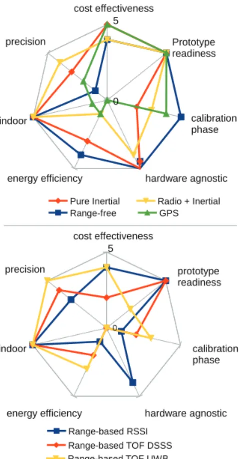
The diagram of figure 1 summarises the expected perfor-mance of each family of solutions. The following axes are used:
cost effectiveness
precision
indoor
energy efficiency hardware agnostic calibration phase prototype readiness 0 5 Range-based RSSI Range-based TOF DSSS Range-based TOF UWB
cost effectiveness
precision
indoor
energy efficiency hardware agnostic calibration phase Prototype readiness 0 5 Range-free
Pure Inertial Radio + Inertial GPS
Fig. 1. Comparison of existing techniques for precise indoor localisation
Cost-effectiveness: this criterion expresses the impact on bandwidth availability. For example, precise ranging is more costly when using narrow-band technologies, Precision: this axis allows the comparison of attainable
ac-curacy,
Indoor: using this criterion, we can identify which technolo-gies can be used in an indoor environment,
Energy efficiency: this criterion expresses the efficiency of the solution in terms of energy consumption, the maxi-mum value corresponding to the proposal which uses the least energy,
Hardware dependency: this criterion expresses the depen-dency to the radio technology used for communication, Calibration: this criterion indicates the calibration cost, Prototype readiness: this criterion indicates whether the
technologies involved can easily be prototyped currently. This prototyping ability depends on availability of the various hardware components, along with the associated software libraries.
The best coverage is given by range-free methods since they can be implemented regardless of the radio technology and the necessary pieces of information can be obtained from existing communications. Unfortunately, these methods are unsuitable since they do not provide precise results.
The GPS as the only localisation source can be set aside as it does not function well in Non Line Of Sight. Purely inertial solutions can be used indoors but, in addition to time and temperature-based degradation of the measurements, these solutions suffer from bias accumulation which must be resolved by periodic recalibration.
Fingerprinting-based solutions can also be used indoors but the calibration phase is very costly while the accuracy is over 5m. In addition, the mobile node may need to collect a significant number of samples from various neighbours in order to build the current fingerprint. Finally, forwarding the fingerprint to the server hosting the fingerprint database is another cost induced by this type of solution.
Since the objective is to achieve precise indoor localisation, the best options are range-based TOF based on DSSS and UWB along with solutions combining radio signal to inertial information. Since the latter requires additional components, we will set it aside in order to minimise energy consumption. Finally, UWB-based solutions can be considered the best choice since they surpass DSSS in terms of cost effectiveness and precision. Unfortunately, this technology is not wide-spread. To the best of our knowledge, this technology is not supported by the existing testbeds. In [13], testbeds of various size deployed around the globe have been reviewed in terms of experimentation support, hardware features, maintenance constraints and mobility. The ten testbeds all use narrow-band technologies: most rely on IEEE 802.15.4 DSSS. As seen previously, this technology is not suitable for precise indoor localisation. Although it may be used for RSSI and ToF-based solutions, the performance can at best lead to room-level accuracy. It is interesting to note that some of these testbeds offer a remote access to their mobile infrastructure (robot-based), providing the nodes in the experiment with an undergone mobility. The robots then autonomously determine their position: for example, in FIT IoT-Lab, a particle filter combines odometry data to laser information in order to track the robot’s position in the environment represented by a map. From this brief analysis, we can conclude that there is a need for a testbed which supports mobility and RF-based precise localisation using the UWB technology. This platform would allow the evaluation of localisation solutions but also the investigation of many interesting topics such as data rate adaptation to distance. For now, our objective is to provide the first building block which is a software library which will enable researchers and programmers to fully exploit the UWB physical layer. This library was developed for the DW1000 chip from DecaWave as it is one of the few UWB transceivers currently available. We will introduce the hardware and soft-ware in the following chapters.
III. PROPOSITION
In this section, we introduce DecaDuino, an open framework which enables the development of Ranging protocols based on the Time-of-Flight concept, using the IEEE 802.15.4-2011 Ultra Wide Band physical-layer. Aside from supporting
rang-ing on WSN nodes, DecaDuino enables the implementation of classic or original MAC protocols on UWB.
A. General description of DecaDuino
In the protocol stack shown in figure 2, DecaDuino is a Physical-layer Service Access Point (PHY-SAP). It provides the two conventional Physical-Data (PD) and Physical Layer Management Entity (PLME) SAPs which enable MAC-level protocols to send/receive data and configure the transceiver (channel, transmission rate, preamble parameters...). Since this framework was designed to aid in the implementation of Time-of-Flight based protocols, DecaDuino also provides access to the Physical-level high precision timer which enable precise message timestamping at both transmission (tT X) and
reception (tRX). Finally, DecaDuino implements advanced
synchronization/timestamping functionalities such as delayed
transmissionand receiver skew evaluation, which are required for centimetre-level localisation using Time-of-Flight.
tTX tRX UWB PHY PD-SAP MAC Upper Layers ToF Timer Ranging protocol PLME-SAP Node A Node B PD-SAP UWB PHY UWB PHY PD-SAP
D e ca D u in o
Fig. 2. Sequence diagram, timers and DecaDuino in the protocol stack
B. Compliant Hardware
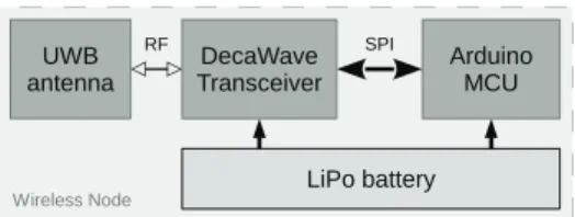
So far, DecaDuino is compatible with the DecaWave transceivers such as DW1000 or DWM1000. It has been integrated in the Arduino ecosystem and is available as an Arduino library. The Arduino ecosystem has been selected as it enables fast prototyping and evaluation on low-cost yet powerful testbeds: this aspect allows these testbeds to be custom-built and deployed locally for proper experiment monitoring. DecaDuino allows the upper layers to make full use of the DecaWave UWB transceiver, provided that an appropriate antenna is attached to the circuit and a Serial Peripheral Interface (SPI) bus connects the transceiver to the microcontroller. Figure 3 illustrates the architecture. An optional battery may facilitate the tests with mobile nodes.
An open-source hardware design called DecaWiNo (also known as Deca-WirelessNode) (figure 4) is available on [14]. On this design, the transceiver is a DWM1000 and the Arduino board is a Teensy 3.2 which embeds an ARM Cortex M4 32-bit MCU rated at 72MHz, with 64kB RAM and 256kB program memory. An OTG USB port completes the set. A Real-Time Clock (RTC) is also available on this board. Many pins are available to drive some external peripherals; an example of driving such external devices is given in the results section of this paper. The node size is only 40mm x 29mm x 5mm: this form factor allows it to be attached to packages and thus to use WSN-based localisation to aid logistics. The DecaWiNo board
DecaWave Transceiver Arduino MCU SPI UWB antenna
Wireless Node LiPo battery
RF
Fig. 3. DecaDuino hardware typical architecture
is compatible with the OpenWiNo framework [15], which is a flexible protocol development and testbed environment.
Fig. 4. A DecaWiNo prototype node
C. DecaDuino functionalities
1) Data service: As a Physical-Layer SAP, DecaDuino en-ables the transmission and reception of frames. The main prim-itives of the IEEE 802.15.4-2011 are implemented in order to support transmission/reception of radio frames, transceiver configuration, etc. Transceiver doze-mode is also available, which enables the implementation and testing of MAC pro-tocols on real scenarios, such as long duration tests including battery-powered mobile nodes. Classic transceiver functional-ities such as address filtering and automatic acknowledgement are also available.
0 20 40 60 80 100 120 140 0 200 400 600 800 1000 1200 1400 1300fps 650fps 325fps
MPDU Length (bytes)
P ract ical T hrou ghpu t (kbps)
Fig. 5. DecaDuino throughput evaluation
Using the 6.8Mbps UWB IEEE 802.15.4 PHY layer, a maximum throughput of 1.2Mbps has been measured on our platform: the setup involved a pair of nodes exchanging frames without acknowledgements and configured to send 120bytes MPDUs (MAC-Protocol Data Unit, i.e. PHY payload) at 1300 frames per seconds. The results are represented on figure 5.
As we can see on the figure, another advantage of the UWB PHY layer is a higher throughput than the classic 250kbps with the 2.4GHz DSSS PHY layer commonly used on WSNs, Zigbee and 6LoWPAN.
2) Ranging service: Given that the objective is to design
ToF-based ranging protocols, DecaDuino proposes the main primitives to achieve this task. As defined by the IEEE 802.15.4-2011 standard, the UWB frames may optionally activate a dedicated bit called R_MARKER which is located in the frame PHY-header. The R_MARKER bit serves as a reference point for precise timestamping of both outgoing and incoming messages. To achieve this timestamping, the DecaWave transceivers include a 40bit/64GHz high precision counter. Considering this counter frequency, the precision of the frame timestamping is 15.625ps, enabling a theoretical ranging precision (trp) of 4.684mm.
trp = c ∗ 15.625 ∗ 10−12= 4.684 ∗ 10−3 with
c = 299792458m.s−1
DecaDuino proposes two primitives to report transmission and reception timestamps to the upper layers to enable frame timestamping and node ranging. An illustration of the usage of these timestamps will be presented in section IV.
3) Advanced functionalities: DecaDuino supports two
ad-vanced features of the DecaWave transceiver: Delayed
Trans-mission and Receiver Skew Evaluation. Theses two
function-alities will definitely pave the way for innovative communica-tions and ranging protocols.
Delayed Transmission enables the MAC-layer to send a frame at a precise time, based on the 64GHz counter. Thanks to this feature, the MAC-layer has the ability to generate a MAC-PDU which includes its future trans-mission timestamp (tT X), and send it at the desired time. With this option enabled, the classic TWR protocol (figure 6-a) may be improved by eliminating the REPLY message (figure 6-b), since t2 and t3 can be carried by the ACK_REP message. This feature is very interesting since it may reduce the number of messages and thus, improve energy performance of the protocols. A ranging performance evaluation of this 2M-TWR (2-Message TWR) protocol will be presented in section IV.
t1 t2 Node A Node B t3 t4 START ACK REPLY (t2, t3) t1 t2 Node A Node B t3 t4 START ACK_REP (t2, t3) Classical TWR (a) 2M-TWR (b)
Fig. 6. Classic TWR vs. 2-Message TWR
Receiver Skew Evaluation enables a receiver to evaluate its own clock frequency offset, also known as the clock skew, relative to another transmitting neighbour, regardless of its role in the network or the topology. This option is a functionality of the DecaWave transceiver, based on the tracking of the received signal during message reception and decoding. With this option enabled, any node may compensate the ranging errors due to delayed messages [16].
IV. RESULTS
In order to evaluate the implementation of DecaDuino, several experiments have been conducted and are presented in this section. The experiments consist in the execution of various ranging protocols implemented on top of DecaDuino, and executed on two DecaWiNo nodes in Line of Sight situations. We will compare the performance obtained using our library to the results published by the manufacturer.
A. Usage of classic ranging protocols: TWR and SDS-TWR
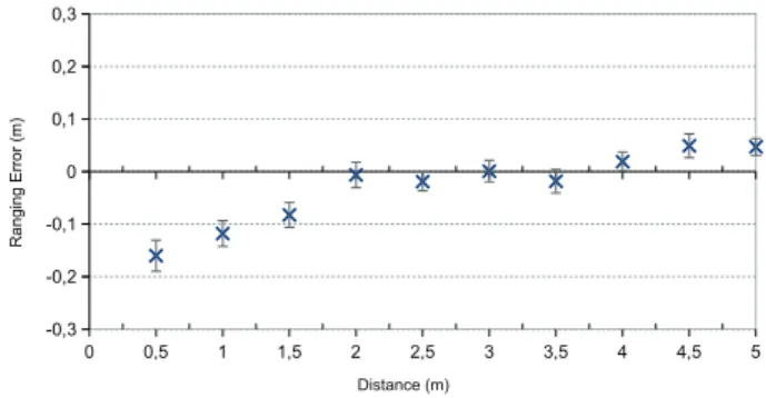
First, two well known ranging protocols have been im-plemented: TWR and SDS-TWR. The experiment scenario consists in 150 executions of each protocol, for 10 distances, from 0.5m to 5m. The two nodes are in Line of Sight (LOS). The obtained results indicate an absolute ranging error less than 15cm with TWR (figure 7), and less than 10cm using SDS-TWR (figure 8). An important characteristic is the small standard deviation: this will allow non-repetitive protocols, with a small number of rangings to quickly achieve cm-level precision in the measured distance. The results also call for the application of a correction method: for example, a regression model could be computed for the obtained error and its slope could be adjusted in order to enhance performance for both short (less than 2m) and long (up than 5m) distances. Finally, as the documentation of the transceiver announces a typical ranging error of 20cm, we can conclude on a good implementation of the library.
0 0,5 1 1,5 2 2,5 3 3,5 4 4,5 5 -0,3 -0,2 -0,1 0 0,1 0,2 0,3 Distance (m) Ranging E rro r (m)
Fig. 7. Ranging error using TWR protocol
B. Improving Ranging precision using Receiver Skew Evalu-ation
In this section, we characterise the advanced functionality
0 0,5 1 1,5 2 2,5 3 3,5 4 4,5 5 -0,3 -0,2 -0,1 0 0,1 0,2 0,3 Distance (m) Ranging E rro r (m)
Fig. 8. Ranging error using SDS-TWR protocol
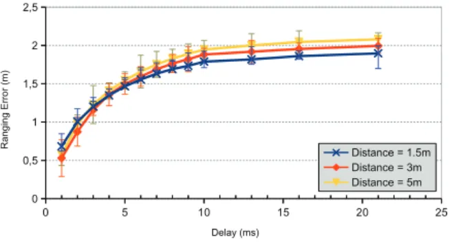
delay is introduced in the classic TWR protocol, between the two messages START and ACK. This delay emphasises the clock drift effect and distorts the ranging process, introducing important ranging errors. For each distance (1m, 3m, 5m) and several delays (1-10, 13, 16 and 21ms), 30 executions of TWR are observed.
In this experiment, the delay is introduced artificially, but in a real-life situation where the ranging functionality is included in the classic traffic, the delay may be introduced by the MAC-layer, for example as an Inter-Frame Delay in a DATA/ACK exchange, or others situations where an important delay may occur between frames. Figure 9 illustrates the ranging errors without the skew correction. As expected, the ranging error increases with the delay and the distances are not exploitable.
0 5 10 15 20 25 0 0,5 1 1,5 2 2,5 Distance = 1.5m Distance = 3m Distance = 5m Delay (ms) Ranging E rro r (m)
Fig. 9. Ranging error using TWR protocol, with an artifical delay
Using the Receiver Skew Evaluation, a correction [16] is possible. Figure 10 illustrates the remaining error after correction. The results show that even in the presence of a long delay between frames, the ranging error remains under 30cm, which is quite acceptable for indoor localisation. This result is very important, since one of the main issues of ranging protocols is their time-constrained aspect; Thanks to this functionality, non time-constrained ranging protocols are become feasible. 0 5 10 15 20 25 -0,5 -0,25 0 0,25 0,5 Delay (ms) Ranging E rro r (m) Distance = 1.5m Distance = 3m Distance = 5m
Fig. 10. Ranging error using TWR protocol, with an artifical delay and skew correction
C. Ranging using Delayed Transmission
In the section, we show the usage of the Delayed
Trans-missionfunctionality, which enables the transceiver to send a
frame at a very precise instant, as described in section III.C.3. The protocol evaluated here is 2M-TWR (2-Message TWR), evoked in section III, with the skew correction applied.
In this experiment, the two protocols TWR (no skew correc-tion) and 2M-TWR (skew correccorrec-tion) are executed 150 times each, for 10 distances, from 0.5m to 5m. The two nodes are in LOS.
As we can see on figure 11, the standard deviation of the ranging error is greater with 2M-TWR. This is due to the highly variable nature of the skew estimates used to feed the applied correction. The current method allows propagation of the variability of the skew to the distance estimates. We are currently studying various approaches in order to smooth the results. Despite this characteristic, the results remain encouraging since the highest error values still allow indoor localisation below room-level precision.
0 0,5 1 1,5 2 2,5 3 3,5 4 4,5 5 -0,5 -0,4 -0,3 -0,2 -0,1 0 0,1 0,2 0,3 0,4 0,5 TWR 2M-TWR Distance (m) R a n g in g E rro r (m )
Fig. 11. Ranging error using classic TWR and 2M-TWR protocols
D. Miscellaneous
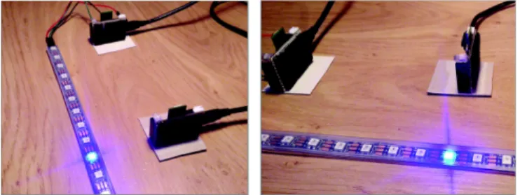
At last, we propose here a visual demonstration of the ranging process in a video [14], illustrated on figure 12. In this scenario, a fixed DecaWiNo execute a ranging session
every 100ms with another node, using the TWR protocol. Once the distance to the other DecaWiNo is estimated, the fixed DecaWiNo represents the distance by driving a LED strip: the corresponding LED, matching with the estimated distance, is powered up in blue. Note that the video’s strip length is 1m and the leds are spaced by 1.65cm. As we can see on the video, using a LED strip gives a direct and real-time feedback of the distance evaluation, which enables very high precision ranging between the two nodes.
Fig. 12. Real-time visualisation of the ranging using the TWR protocol
V. CONCLUSIONANDPERSPECTIVES
The Internet of Things is expected to revolutionise the net-working world. New applications will come to life, involving swarms of connected objects which will require the ability to autonomously determine their position. Outdoors applications will definitely rely on the GPS, as long as this technology’s power consumption can be reduced. Indoor environments as well as locations unreachable to the GPS signal will require wireless local solutions. The iBeacon is an example of such products and provides a ranging functionality with a precision level of a few metres. In order to achieve higher precision, a signal which is more reliable than RSSI is necessary. ToF is one such signal and allows a precision of a few centimetres through the execution of a ranging protocol between a mobile and fixed nodes.
In this paper, we introduce DecaDuino and DecaWiNo, which is the first platform offering the means to implement wireless communications based on UWB technology and also supporting precise distance estimation between nodes. Our library is built on open software and hardware tools which are cost-effective and have a fast learning curve. As shown through the results, integrating ranging in the interface to the PHY layer opens many possibilities for research, without any addi-tional hardware (Infra-Red, Ultra-Sound, GPS...). The ability to start transmission of the frame at a time specified inside the same message has allowed us to propose a new ranging protocol which reduces the number of frames exchanged while attaining a precision of 15cm. We are currently designing an optimised MAC-layer which will support the ranging process natively, without additional traffic. Using this library, we also proposed [16] a correction method for the clocks involved in a TWR which reduced the impact of the delay between messages. While the correction is hardware-dependant, we are currently investigating how to evaluate the skew without
using the transceiver information. In order to evaluate our future contributions in the field of ranging and localisation, we are also building a dedicated test environment which will offer controlled motion of the nodes along rails. Finally, our solution will also be used in industrial environments since a project involving several industrial partners has been launched in the field of cold chain integrity monitoring. A last perspective concerns the extension of DecaDuino to others UWB transceivers.
ACKNOWLEDGMENT
The authors would like to thank DecaWave Ltd. for their support in the development of DecaDuino.
REFERENCES
[1] L. Gui, T. Val, A. Wei, R. Dalce, Improvement of Range-free Localization Technology by a Novel DV-hop Protocol in Wireless Sensor Networks. Ad Hoc Networks Journal, Elsevier, Vol. 24 N. Part B, January 2015. [2] N. Bulusu, J. Heidemann, D. Estrin, GPS-less low-cost outdoor
localiza-tion for very small devices, in Personal Communicalocaliza-tions, IEEE, vol.7, no.5, pp.28-34, Oct 2000 doi: 10.1109/98.878533
[3] W. Kang, Y. Han, SmartPDR: Smartphone-Based Pedestrian Dead Reck-oning for Indoor Localization, Sensors Journal, Vol. 15, no 5, May 2015 [4] T. Iwase, R. Shibasaki, Infra-free indoor positioning using only smartphone sensors, in Indoor Positioning and Indoor Navigation (IPIN), 2013 International Conference on, 28-31 Oct. 2013 doi: 10.1109/IPIN.2013.6817864
[5] G. Conte, M. De Marchi, A.A. Nacci, D. Sciuto, BlueSentinel: A first approach using iBeacon for an energy efficient occupancy detection system, 1st ACM International Conference on Embedded Systems For Energy-Efficient Buildings (BuildSys), 5 nov 2014.
[6] A. Buchman, A. Erdei, C. Lung, Indoor localisation method based on existing WLAN infrastructure, 20th International Symposium for Design and Technology in Electronic Packaging, 2014
[7] M. Ros, B. Schoots, M. D’Souza, Using Context-Aware Sub Sorting of Recevied Signal Strength Fingerprints for Indoor Localisation, 2012 [8] S. B. Wibowo, M. Klepal, Rao-Blackwellized Particle Filter for Pattern
Matching Indoor Localisation, 2010
[9] IEEE 802.15.4-2011 standard, http://www.ieee802.org/15/pub/TG4.html [10] M. Ghavami,L. B. Michael, R. Kohno, “Ultra wideband signals and
systems in communication engineering” Wiley Editions 2007
[11] A. Behboodi, N. Wirstrom, F. Lemic, T. Voigt, A. Wolisz, Interference Effect on Localization Solutions: Signal Feature Perspective, in Vehicular Technology Conference (VTC Spring), 2015 IEEE 81st , vol., no., pp.1-7, 11-14 May 2015 doi: 10.1109/VTCSpring.2015.7145885
[12] T. Ye, M. Walsh, P. Haigh, J. Barton, and B. O’Flynn, Experimental impulse radio IEEE 802.15.4a UWB based wireless sensor localization technology: Characterization, reliability and ranging, ISSC 2011, 22nd IET Irish Signals and Systems Conference, Dublin, Ireland, 23-24 Jun 2011.
[13] A. Tonneau, N. Mitton, J. Vandaele, How to choose an experimenta-tion platform for wireless sensor networks?, Elsevier Adhoc Networks, Elsevier, 2015, 30, pp.12 <hal-01147346>
[14] A. van den Bossche, DecaWiNo ressources,
http://www.irit.fr/~Adrien.Van-Den-Bossche/DecaWiNo, last accessed feb. 2016
[15] A. van den Bossche, T. Val, WiNo : une plateforme d’émulation et de prototypage rapide pour l’ingénierie des protocoles en réseaux de capteurs sans fil, Journées francophones Mobilité et Ubiquité (UBIMOB 2013), Nancy, France, June 2013 (in French, extended english version currently under review)
[16] N.I. Fofana, A. van den Bossche, R. Dalce, T. Val, Prototypage et analyse de performances d’un système de ranging pour une localisation par UWB, Colloque Francophone sur l’Ingénierie des Protocoles (CFIP 2015), Paris, France, July 2015 (in French, extended english version currently under review)