HAL Id: tel-01436641
https://tel.archives-ouvertes.fr/tel-01436641
Submitted on 16 Jan 2017
HAL is a multi-disciplinary open access
archive for the deposit and dissemination of sci-entific research documents, whether they are pub-lished or not. The documents may come from
L’archive ouverte pluridisciplinaire HAL, est destinée au dépôt et à la diffusion de documents scientifiques de niveau recherche, publiés ou non, émanant des établissements d’enseignement et de
Self-repair rejuvenates mechanically stressed
microtubules
Laura Schaedel
To cite this version:
Laura Schaedel. Self-repair rejuvenates mechanically stressed microtubules. Biological Physics
THÈSE
Pour obtenir le grade de
DOCTEUR DE LA COMMUNAUTÉ UNIVERSITÉ
GRENOBLE ALPES
Spécialité : Physique Pour Les Sciences Du Vivant Arrêté ministériel : 7 août 2006
Présentée par
Laura SCHAEDEL
Thèse dirigée par Manuel THERY
préparée au sein du Laboratoire de Physiologie Cellulaire et
Végétale dans l'École Doctorale de Physique
Self-repair rejuvenates
mechanically stressed
microtubules
Thèse soutenue publiquement le 1 juillet 2016, devant le jury composé de :
Mr Bertrand FOURCADE
Professeur, Laboratoire Interdisciplinaire de Physique, UGA Grenoble (Président)
Mme Marileen DOGTEROM
Professeur, Delft University of Technology – Netherlands (Rapporteur)
Mr Denis CHRETIEN
Directeur de Recherche, Université de Rennes 1 (Rapporteur)
Mme Isabelle ARNAL
Chargée de Recherche, Grenoble Institut des Neurosciences (Examinateur)
Mr Gary BROUHARD
Professeur, McGill University – Canada (Examinateur)
Mr Igor KULIC
Chargé de Recherche, Institut Charles Sadron Strasbourg (Examinateur)
CONTENTS
Contents
List of Abbreviations 1
1 Introduction 3
1.1 The eukaryotic cytoskeleton . . . 3
1.2 Microtubule networks in cells . . . 6
1.3 Microtubule structure . . . 9
1.4 The tubulin heterodimer is a GTPase . . . 12
1.5 Microtubule dynamics . . . 16
1.6 Microtubule mechanical properties . . . 23
1.7 Microtubule mechanics in cells . . . 26
1.7.1 Mechanical properties of cellular microtubules . . . 26
1.7.2 Forces on cellular microtubules . . . 27
1.8 Motivation . . . 33
2 Results 35 2.1 Study 1. Schaedel et al., Nature Materials, 2015 . . . 35
2.1.1 Introduction . . . 35
2.1.2 Conclusions and perspectives . . . 68
2.1.3 Limitations of the study . . . 73
2.2 Study 2. Aumeier / Schaedel et al., Nature Cell Biology, 2016 . . . . 77
2.2.1 Introduction . . . 77
2.2.2 Conclusions and perspectives . . . 102
2.2.3 Limitations of the study . . . 106
3 Conclusions and Perspectives 108
List of Abbreviations
+TIP Microtubule plus end directed motor
AF Actin filament
ATP Adenosine triphosphate
BRB Brinkley Reassembly Buffer
CLASP CLIP-associating protein
CLIP Cytoplasmic linker protein
E Young’s modulus
EB3 End binding protein 3
F-actin Filamentous actin
Gamma-TuRC Gamma-tubulin ring complex
GDP Guanosine diphosphate GTP Guanosine triphosphate I Moment of inertia IF Intermediate filament κ Bending stiffness kB Boltzmann constant L Length LP Persistence length
MACF Microtubule-actin crosslinking factor
MAP Microtubule Associated Protein
MT Microtubule
MTOC Microtubule-organizing center
PEG Poly(ethylene)glycol
t1/2 half-life period
1
Introduction
1.1
The eukaryotic cytoskeleton
The eukaryotic cytoskeleton is essentially an intracellular biopolymer scaffold and it is, contrary to what its name may suggest, a highly dynamic system far from thermodynamic equilibrium. Yet it is well-ordered; the high degree of internal or-ganization in cells is mostly due to the cytoskeleton (Huber et al., 2013; Gupta et al., 2015). Apart from spatially organizing cellular content, it also serves to connect the cell to the extracellular space, transports cargoes across the cell and generates forces that allow the cell to move and change shape (Fletcher and Mullins, 2010). The cytoskeletal organization is extremely variable from one cell to another and even, temporally and spatially, within the same cell, reflecting another important property: Fast adaptation to cellular needs, requiring rapid turnover and reorgani-zation (Komarova et al., 2002). The prize the cell pays to maintain an array that can rapidly adapt is energy in the form of adenosine triphosphate (ATP) or guanosine triphosphate (GTP); hydrolysis of these nucleotides is an exothermic process and the energy released can fuel fast cytoskeletal remodeling.
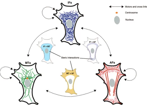
The cytoskeleton of eukaryotic cells consists of three classes of filaments: Actin filaments (AFs), microtubules (MTs) and intermediate filaments (IFs) (see Fig. 1), which are all fiber-like structures made of many individual building blocks (monomers or dimers). All three polymers grow and shrink by addition and sub-traction of these building blocks. While actin filaments mostly appear in the form of cross-linked networks, microtubules are hollow polymer tubes that mostly appear as individual fibers or bundles (Fletcher and Mullins, 2010; Huber et al., 2013). Inter-mediate filaments are more heterogeneous; there are several types made of different protein components (Wagner et al., 2009).
(a) (b)
(c) (d)
Figure 1: Actin filaments (a), microtubules (b) and intermediate filaments (c) are the three major components of the cytoskeleton. The images show the organization of the different filaments in a Huh7 cultured human hepatocyte cell. (d) shows a superimposed image. (From Omary et al., 2006)
A way to characterize the stiffness of cytoskeletal filaments is the persistence length.
The persistence length LP is the length over which a (bio-)polymer bends
signifi-cantly under thermal fluctuations (see Fig. 2), and can be defined as ht(0) · t(s)it = e−s/LP
where s is the distance between two points along the polymer, t(s) is the tangent
Figure 2: The persistence length of a polymer is the characteristic distance over which the tangent vectors along the polymer become uncorrelated due to thermal fluctuations.
2002; Martin 2013). The persistence length is related to the bending stiffness κ by
LP =
κ kBT
= EI
kBT
where kB is the Boltzmann constant, T the absolute temperature, E the Young’s
modulus and I the moment of inertia of the polymer.
The persistence length of microtubules is on the order of millimeters. As micro-tubule lengths L in cells are typically on the order of micrometers and therefore L << LP, microtubules are considered rigid on the scale of cells, contrary to the
semi-flexible actin filaments and the flexible intermediate filaments (see Fig. 3).
Dynamics and organization of cytoskeletal filaments are not only determined by the inherent properties of their components, but also by interactions with associated pro-teins that can nucleate, sever, cross-link, weaken, strengthen, or transport filaments (Eriksson et al., 2009; van der Vaart et al., 2009; Roll-Mecak and McNaly, 2010; Su et al., 2012; Huber et al., 2013). Cytoskeletal components don’t fulfill a single task, their multi-functionality is one of their fundamental properties. For instance, microtubules are essential for cell division, but also for intracellular transport and cell motility.
Figure 3: Microtubules are rigid on cellular length scales, while actin filaments are
semi-flexible and intermediate filaments are considered flexible. (Adapted from www.
uni-leipzig. de/ ~ pwm/ web/ ?section= introduction&page= cytoskeleton )
1.2
Microtubule networks in cells
In cells, microtubules fulfill a variety of tasks. They are implied in intracellular transport, cell migration and cell division and constitute in large part axons, cilia and flagella (Mimori-Kiyosue, 2011). Cellular microtubules are mostly nucleated and grow from microtubule-organizing centers (MTOCs). Examples of MTOCs are basal bodies, which are associated with cilia and flagella, and centrosomes, which are e.g. involved in chromosome segregation during cell division. Additionally, non-centrosomal nucleation is found in cells (Bartolini and Gundersen, 2006).
Microtubules in cells are several orders of magnitude longer than their diameter, and often span the intracellular space to be able to carry cargoes efficiently and drive changes in cell shape (Hawkins et al., 2010). Yet they rapidly turn over, with
a half-life period of t1/2 ≈ 10 min (Gundersen and Bulinski, 1988). A subset of
mi-crotubules, however, is sometimes selectively stabilized, like during neuronal axon determination (Hammond et al., 2010; Stiess et al., 2010; Winans et al., 2016) and at
the leading edge of migrating cells (Gundersen and Bulinski, 1988; Waterman-Storer and Salmon 1997; Wadsworth 1999). A way for the cell to tag a subpopulation of mi-crotubules e.g. for stabilization is by post-translational modifications. Microtubule post-translational modifications are enzymatic modifications on the amino acids at various sites, including acetylation, glutamylation and detyrosination, which can oc-cur both before and after polymerization (Gundersen and Bulinski, 1988; Song and Brady, 2015).
In addition, a variety of microtubule-associated proteins (MAPs) and microtubule plus-end tracking proteins (+TIPs) can influence microtubule dynamics and there-fore control and actively remodel microtubule networks (Cassimeris 1993; Levy et al., 2005; Vandecandelaere et al., 1996). They can also slide, pull, anchor and guide microtubules, and, in this way, affect their organization in the cell (Mimori-Kiyosue 2011).
Microtubules interact with other cytoskeletal components by different means (see Fig. 4). Due to the dense packing of filaments e.g. at the periphery of the cell, where actin filaments form dense networks, steric interactions alone can lead to entangle-ment of microtubules and translocate them: Retrograde flow from the lamellum pushes on microtubules, making them move along with the filamentous actin (F-actin). F-actin bundles can also guide the growth of microtubules, which are often found to align with the bundles (Salmon et al., 2002; Mandato and Bement 2003; Huber et al., 2015). Additionally, there are specific proteins that mediate interac-tions between cytoskeletal filaments, like the cross linking of actin filaments and microtubules by MACF (Leung et al., 1999, Sun et al., 2001) and kinesin-mediated transport of intermediate filaments along microtubules (Prahlad et al., 1998; Her-mann and Aebi, 2000). Moreover, microtubules and actin filaments can influence each other’s organization in a more indirect way, through biochemical signaling pathways (Waterman-Storer et al., 1999; Zaoui et al., 2008; Pertz 2010).
Figure 4: Microtubules (MTs), intermediate filaments (Ifs) and actin filaments (Ifs) interact via different mechanisms with another: Unspecific, steric interactions occur in overlapping regions as well as crosslinking and motor protein mediated interac-tions. (Adapted from Huber et al., 2015)
1.3
Microtubule structure
Microtubules are biopolymers made of tubulin heterodimers. Each dimer consists of two closely related 55 kDa globular proteins called alpha and beta tubulin. The dimers assemble longitudinally into so-called protofilaments, which form lateral bonds between each other and, in this way, arrange into a closed tube of approx. 25 nm outer diameter and 17 nm inner diameter (Desai and Mitchison, 1997, see Fig. 5a). Microtubules undergo assembly and disassembly by non-covalent addition and subtraction of tubulin dimers at the ends.
Bonds between protofilaments are anisotropic and three-dimensional (Nogales et al, 1999; Sui et al., 2010; Huber et al., 2013) and are either formed between equal subunits (alpha-alpha and beta-beta), yielding a B-lattice configuration, or between unequal subunits (alpha-beta), resulting in an A-lattice (see Fig. 5b). B-lattice con-figurations are by far more common in vitro, while in vivo A-lattice concon-figurations can be observed in cilia, where microtubules with an A-lattice have a non-complete B-lattice microtubule attached to them (Amos and Klug, 1974). Axonemes in vivo also nucleate A-lattice microtubules (Scheele et al., 1982). There is evidence that the configuration of the microtubule lattice influences microtubule stability (Katsuki et al., 2014).
Energy values of lateral and longitudinal bonds between dimers have been estimated by simulations in silico or inferred from experiments by various groups; values vary from -3 kT to -15 kT for lateral bonds and -6 kT to - 20 kT for longitudinal bonds (VanBuren et al., 2002; VanBuren et al., 2005; Efremov et al., 2007; Molodtsov et al., 2005; Wu et al., 2009; Wu et al., 2012). Most groups found longitudinal bonds to be considerably stronger than lateral bonds. Lateral interactions are mediated by loop-loop interactions. Loops are rather disordered secondary protein structures, which in case of tubulin have been proposed to provide the necessary flexibility to
(a) (b)
Figure 5: (a) Microtubules are made of tubulin dimers. Each dimer consists of two
globular, structurally similar 55 kDa proteins, called alpha (light green) and beta (dark green) tubulin. Dimers associate longitudinally into protofilaments, which form lateral bonds and close into a hollow tube of 25 nm diameter. (b) In a B-lattice, lateral bonds are formed between equal subunits (alpha-alpha and beta-beta interactions). The helical staggering of dimers leads to a discontinuity called ’seam’, where lateral bonds between alpha and beta subunits form. In an A-lattice, lateral interactions form exclusively between unequal subunits, and there is no seam. (From Hawkins et al., 2010)
Cellular microtubules usually consist of 13 protofilaments (Ledbetter and Porter, 1964; Evans et al., 1985), though protofilament numbers between 9 and 17 have been observed (Chr´etien and Wade, 1991; McIntosh et al., 2009). Indeed post-translational modifications such as acetylation (Cueva et al., 2012) and drugs like taxol (D´ıaz et al., 1998) are known to favor a specific protofilament number, re-spectively. Interestingly, the protofilament number can vary not only from one microtubule to another, but even along the length of the same microtubule, creat-ing a protofilament mismatch (Chr´etien et al., 1992).
Neighboring protofilaments are staggered, yielding a helical arrangement of dimers in the microtubule lattice and establishing another important parameter to char-acterize the microtubule lattice: The so-called helix start number is defined as the number of monomers that the helix spans in each turn in the longitudinal direction. For an uneven helix start number and a B-lattice, a discontinuity is created where an alpha subunit interacts laterally with a beta subunit at the so-called seam, breaking the helical symmetry of the microtubule (see Fig. 5b). Even protofilament numbers on the other hand lead to helical symmetry, involving only alpha-alpha and beta-beta subunit interactions. Three- and four-start helices are most common (Sui and Downing, 2010). In all but the 13-3 lattice (13 protofilaments, three-start helix), protofilaments are slightly skewed, resulting in a super twist that is left-handed for 14-3 microtubules and right-handed for 11-3, 12-3, 15-4 and 16-4 microtubules (Wade et al., 1990; Sui and Downing, 2010; see Fig. 6). The biological function of the seam is not yet clear; however, it has been proposed that it presents a weak structure in the microtubule (Sept et al., 2003). Indeed microtubules with ectopic A-lattice seams polymerized in vitro are less stable than B-lattice microtubules (Katsuki et al., 2014).
(a) (b)
Figure 6: (a) Except for the 13-3 lattice configuration, the protofilaments exhibit a slight supertwist. (b) Lateral curvature of a 16 protofilament and an 11 protofilament lattice. The difference in curvature is thought to be accommodated by flexible lateral interactions. (From Sui and Downing, 2010)
1.4
The tubulin heterodimer is a GTPase
Microtubule dynamics is powered by the energy released during GTP hydrolysis. Each alpha beta tubulin dimer binds two nucleotides (GTP or GDP), each one at the interface between two monomers, respectively, so that the nucleotide in one monomer interacts with the next monomer at the longitudinal interface (see Fig. 7). The nucleotide bound to alpha tubulin is buried at the intradimer interface (called N-site) and is therefore non-hydrolyzable and non-exchangeable (Nogales et al., 1998). It has been proposed that it has a structural role (Menendez et al., 1998). The nucleotide bound to beta tubulin on the other hand can be hydrolyzed and exchanged. It is located at the E-site of beta tubulin and it is exposed to the solvent at the microtubule plus end (Nogales et al., 1998).
During microtubule growth, the incoming alpha tubulin interacts with the GTP binding site in the beta subunit, which is thought to contribute to GTP hydrolysis.
Figure 7: Both alpha and beta tubulin have a GTP binding pocket, located at the longitu-dinal interface between neighboring subunits. The GTP bound to alpha tubulin is buried and non-exchangeable, whereas the GTP bound to beta tubulin is hydrolyzed to GDP as the dimer is incorporated into the microtubule. Upon hydrolysis, the dimer undergoes conformational changes and becomes more unstable in the lattice. (From Alushin et al., 2014)
Therefore, the minus end of a tubulin subunit can be seen as GTPase activating protein (Choi et al., 1998; Nogales et al., 1998; Nogales et al., 1999; Anders and Botstein, 2001). Hydrolysis of GTP bound to tubulin and subsequent phosphate
release takes place after incorporation at a rate of about 0.25 min−1 (Carlier et
al., 1981). At sufficiently high free GTP tubulin concentration, GTP hydrolysis is slower than the addition of new GTP tubulin at the growing end, creating a GTP tubulin cap (Carlier and Pantaloni 1981; Carlier et al., 1987). After hydrolysis, the GDP nucleotide becomes locked in the E site until the dimer dissociates from the microtubule. Free tubulin dimers have a higher affinity for GTP than for GDP and therefore exchange hydrolyzed nucleotides rapidly.
For a long time free GTP tubulin dimers were thought to be straight, favoring their incorporation into the lattice, in contrast to free GDP tubulin dimers which where shown to be slightly curved (Kirschner et al., 1974; Rice et al., 2008). It was there-fore hypothesized that hydrolysis of tubulin bound GTP is accompanied by a switch to a curved state. However, crystal structures of free GDP and GTP bound tubulin indicate that both GDP and GTP tubulin exhibit a similar intradimer curvature (Nawrotek et al., 2011; Ayaz et al., 2012; Pecqueur et al., 2012) which is incom-patible with the microtubule lattice, indicating that GTP tubulin dimers have to undergo conformational changes involving straightening upon incorporation into the lattice (Buey et al., 2006; Rice et al., 2008; Nawrotek et al., 2011). Whether these conformational changes are strictly related to the nucleotide state of the dimer or whether they occur subsequently as a result of the interplay between the nucleotide state and the interactions with other dimers in the microtubule lattice is still under debate. However, it has been shown that GDP tubulin which is incorporated into the lattice changes microtubule dynamics compared to GTP tubulin that hydrolyses to become GDP tubulin after incorporation (Valiron et al., 2010). In addition, Car-lier et al. suggested that GTP hydrolysis is not strictly coupled to polymerization
and occurs in a subsequent step (Carlier et al., 1981). How the hydrolysis rate is influenced by the conformational and nucleotide states of the neighboring dimers still has to be elucidated, but there is evidence that a coupled random model, where hydrolysis occurs randomly except for the terminal dimer which takes longer to hy-drolyze due to lacking interactions with the GTP pocket at the E-site, is most likely (Bowne-Anderson et al., 2013).
Upon hydrolysis, lattice bound tubulin dimers undergo structural changes involving a compaction of the interdimer interface, conformational changes especially in alpha tubulin and a weakening of the longitudinal bonds (Alushin et al., 2014). Part of the energy released upon GTP hydrolysis is therefore used to deform the tubulin dimer, in a way that is believed to destabilize the dimer in the microtubule and induce mechanical stress while it is constrained by the lattice. Consequently, GDP tubulin is less tightly bound in the microtubule lattice; it easily falls off when it is not stabilized by more stably bound GTP tubulin dimers at the end of the microtubule. Microtubules made of GDP tubulin are therefore metastable structures; as soon as the protecting GTP tubulin cap is lost, depolymerization is initiated (Carlier et al., 1987). The size of the GTP cap has been determined indirectly using EB1, a plus end tracking protein that seems to recognize the nucleotide state of lattice bound tubulin and to preferentially bind GTP tubulin (Zanic et al., 2009). EB1 localizes to growing microtubule ends, and its signal decays exponentially with the distance from the tip (Bieling et al., 2007). However, it doesn’t reach the very tip of the microtubule (Maurer et al., 2014). This suggests a ’patchwork’ GTP cap that consists of dimers in different nucleotide and / or conformational states.
1.5
Microtubule dynamics
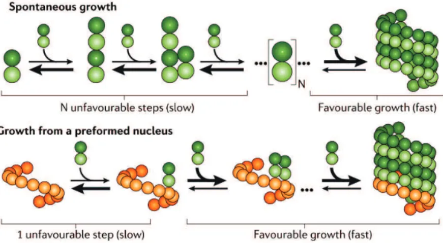
As longitudinal contacts between tubulin dimers occur between alpha and beta sub-units, the resulting microtubule is polar: The end where beta tubulin is exposed tends to grow faster and is therefore called plus end, while the slower growing minus end exposes alpha tubulin. Microtubule polarity is used by plus and minus end directed molecular motor proteins for directional transport along microtubules. In vitro, the rate-limiting step in microtubule polymerization is nucleation (see Fig. 8). Oligomerization of tubulin dimers is energetically unfavorable and therefore slow. Once a sufficiently large oligomer is formed, growth becomes favorable and faster. In the absence of co-factors, the critical tubulin concentration for sponta-neous nucleation is 20 - 40 µM (Br´e et al., 1990; Kollman et al., 2011; Wieczorek et al., 2015). Cells therefore have nucleators like the gamma-tubulin ring complex (gamma-TuRC), which mimics the 13 protofilament architecture of the microtubule and accelerates nucleation.
Microtubule growth velocity depends on several factors, like free tubulin
concentra-tion, Mg2+
concentration, pH, ionic strength (Olmsted and Borisy, 1975; Kuchnir Fygenson et al., 1994) and microtubule associated proteins that assist polymeriza-tion (Akhmanova and Steinmetz, 2010). In general, for condipolymeriza-tions used in vitro, microtubule growth rates are around a few µm/min and increase linearly with free tubulin concentration (Carlier et al., 1987; Walker et al., 1988; Kinoshita et al., 2001). In vivo, growth rates are often substantially higher; They can range from 7 - 42 µm/min, depending on the cell type and the stage in the cell cycle (Cassimeris et al., 1988; Kinoshita et al., 2001; Piehl and Cassimeris, 2003; Srayko et al., 2005; Komarova et al., 2009). A possible explanation for the discrepancy in growth rates observed in vivo vs. in vitro are proteins that assist polymerization. For example, XMAP215 and EB1 have been shown to increase polymerization rates in vitro to physiological levels (Zanic et al., 2013).
Figure 8: Microtubule nucleation is a slow, energetically unfavorable process, but it can be accelerated considerably by the presence of a nucleus (e.g. a gamma-tubulin ring complex). (Adapted from Kollmann et al., 2011)
During growth, some protofilaments are longer than others, creating differences in the number of lateral bonds (Chr´etien et al., 1995; Brouhard 2015); some protofil-aments protrude up to 100-200 nm (Mandelkow et al., 1991). It is therefore nec-essary to treat each protofilament separately to determine rate constants. In this ’2D’ model, GTP tubulin dimers are fast to bind to protofilament ends, with a rate
constant of 4 µM−1s−1. However, they fall off rapidly if they are not stabilized by
lateral bonds with other dimers. Each bond formed with neighboring dimers stabi-lizes the newly incorporated dimer a bit more (VanBuren et al., 2005; Gardner et al., 2011; Fig. 9).
The 2D model can explain some experimental observations like fluctuations in the growth dynamics of individual microtubules (Schek et al., 2007). However, it fails to explain other phenomena, like the fact that paclitaxel, a drug known to stabilize interdimer bonds, slows down microtubule growth (Prota et al., 2013; Zanic et al., 2013). We lack taking into account intrinsic curvature of GTP tubulin and angles
Figure 9: According to the 2D model, tubulin dimers binding to the ends of protofilaments fall off rapidly unless they are stabilized by lateral bonds. (Adapted from Brouhard, 2015.)
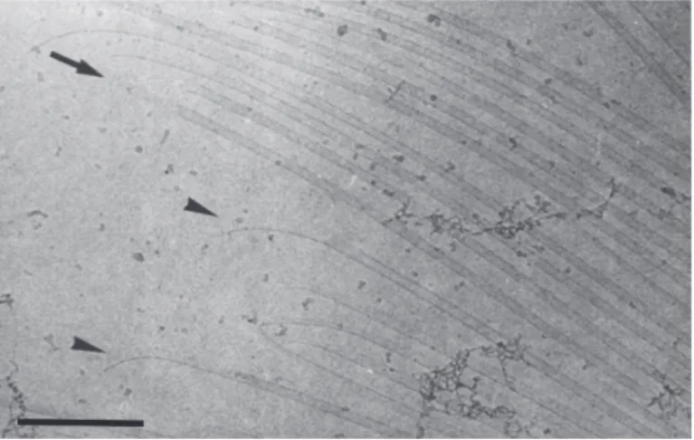
of alpha beta tubulin bonds (Brouhard 2015). Growing protofilaments are either
straight or, especially when they extend far beyond others, slightly bent (0-5◦ per
dimer); microtubule tips shift from a blunt to a more tapered appearance as the concentration of free tubulin increases (Chr´etien et al., 1995; see Fig. 10). Micro-tubules have been proposed to form sheets at growing ends which later close into tubes (Chr´etien et al.; 1995); and a computational study proposed the existence of alternative lateral tubulin bonds during microtubule assembly that could explain the observation of sheet-like structures undergoing conformational changes to form a tube (Wu et al., 2012). A pure chemical kinetics view of microtubule dynamic instability is therefore not sufficient; connecting mechanical and biochemical aspects seems a key to understand microtubule dynamics (Kueh and Mitchison, 2010).
Figure 10: Protofilaments at growing microtubule ends often look slightly curved. Micro-tubules have been proposed to form sheets which later close into tubes. Scale bar: 300 nm. (Adapted from Chr´etien et al., 1995)
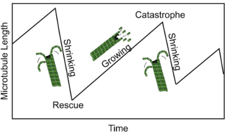
Overall microtubule dynamic behavior is more complex than mere addition of sub-units. Elongation phases are stochastically interrupted by sudden switches to de-polymerization, called catastrophes. Depolymerizing microtubules on the other hand can switch back to growth by so-called rescue events. Together, these phenomena describe what is called ’dynamic instability’ (see Fig. 11).
Catastrophes are thought to occur when the stabilizing GTP cap at the end of the microtubule is lost. Catastrophe frequency accordingly decreases with free tubulin concentration. It is generally higher for plus ends than for minus ends (Walker et al., 1988). Interestingly, the probability that the plus end of a microtubule under-goes catastrophe increases with time, presumably because microtubule ends become more tapered and therefore more likely to switch to shrinking, a process called ’ag-ing’ (Gardner et al., 2011; Coombes et al., 2013). This shows that catastrophe of the plus end has to be viewed as a multistep process (Odde et al., 1995).
Figure 11: Microtubule dynamic instability phases. (Adapted from Hawkins et al., 2010)
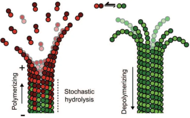
Upon depolymerization, the elastic energy stored in the GDP tubulin dimers is re-leased when the depolymerizing protofilaments break the lateral bonds between each
other and curl into so-called ram’s horns, with a curvature of around 12◦ per dimer
(Chr´etien et al., 1995; see Fig. 12). Microtubules therefore can be used to do work not only during growth, but also during disassembly. Shortening rates in vitro are similar at the two ends and much faster than growth rates: They have been mea-sured around 20 - 30 µm/min and are independent of the free tubulin concentration (Walker et al., 1988; Kinoshita et al., 2001).
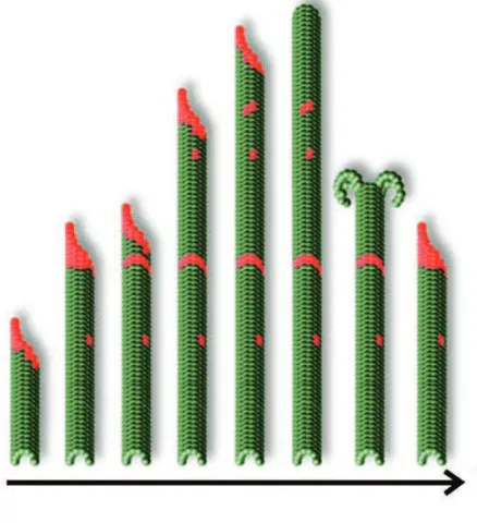
Rescue is much less well understood than the other phases of dynamic instability (Brouhard 2015). It increases with free tubulin concentration, but it is much less sensitive to tubulin concentration than the catastrophe frequency, especially at the plus end which has a lower rescue frequency than the minus end (Walker et al., 1988). This suggests that rescue is not a result of stochastic GTP-tubulin addition at the shrinking microtubule end, and that rather some features previously embedded in the lattice might disrupt depolymerization (Gardner et al., 2013). Indeed, it has been suggested that non-hydrolyzed GTP-tubulin remnants in the lattice, so-called GTP islands, are responsible for microtubule rescue (Dimitrov et al., 2008; see Fig. 13). How these islands are created and why they don’t hydrolyze is, however, unknown.
Figure 12: Microtubule assembly and shrinkage. During microtubule growth, GTP tubulin dimers (red) add at the ends of protofilaments which slightly curve outward. Upon incor-poration into the microtubule, the GTP is hydrolyzed (green), inducing mechanical stress in the lattice. The resulting metastable lattice that is stabilized by a cap of GTP tubulin dimers at the end of the microtubule. When the GTP cap is lost, the protofilaments curl outwards and the microtubule disassembles. (Adapted from Alushin et al., 2014)
In vivo, linker proteins might locally promote rescue by halting depolymerization and assisting regrowth (Komarova et al., 2002; Al-Bassam et al., 2010).
Figure 13: GTP islands are hypothesized to be rescue sites. As a microtubule grows, islands of GTP tubulin are proposed to be excluded from hydrolysis. During depoly-merization, the GTP remnants might stabilize the lattice, leading to regrowth of the microtubule. (Adapted from Dimitrov et al., 2008)
1.6
Microtubule mechanical properties
Microtubules are very stiff biopolymers. Their flexural rigidity (or bending stiff-ness), defined as their resistance to bending, is comparable to carbon nanotubes (Hawkins et al., 2010). If tubulin were a homogeneous and isotropic material, its Young’s modulus would be around 1.2 GPa, similar to rigid plastic (Gittes et al., 1993). However, due to the anisotropy of tubulin bonds, microtubules exhibit at the same time a high lateral deformability and a high longitudinal stiffness (Sui et al, 2010; Huber et al., 2013). This property can be observed in other biological materials, such as bamboo and wood, which are also more rigid longitudinally in order to increase resistance to breaking by external forces (Hawkins et al., 2010). Due to difficulties to measure microtubule mechanical properties in living cells, most knowledge about microtubule mechanics comes from in vitro experiments. Many different groups measured in vitro microtubule bending stiffness with different tech-niques. Most techniques directly exert a force to measure microtubule stiffness, e.g. using flow, optical tweezers, atomic force microscopy or trajectories of microtubules transported by surface-attached kinesin molecules (Hawkins et al., 2010; see Fig. 14). Thermal fluctuations are used as a passive way to probe microtubule stiffness, relying on slight bending induced by thermal energy only. Due to the inherent stiff-ness of microtubules, this approach is limited to long microtubules.
Surprisingly, the stiffness values found by the different groups vary substantially: Persistence length estimates range from 0.03 mm to 46.8 mm (Hawkins et al., 2010). This variability is likely to reflect the influence of the measurement technique as well as the way microtubules are grown. Indeed mechanical properties of microtubules are influenced by a number of factors. For example, some neuronal MAPs are able to increase microtubule stiffness (Mickey and Howard 1995), while MAP65, which is associated to spindle formation and stabilization, promotes flexibility (Portran et
Figure 14: Examples of microtubule persistence length measurement techniques. makes microtubules less rigid (Dye et al., 1993). Even growth velocity has been shown to affect microtubule stiffness: Microtubules grown faster are more flexible, probably due to structural defects in the lattice which are more likely to occur dur-ing fast polymerization (Kurachi et al., 1995; Janson and Dogterom 2004). These defects have been visualized with atomic force and electron microscopy, revealing different types of lattice irregularities: Protofilament mismatches, where a switch between different protofilament numbers occurs within a microtubule (Chr´etien et al., 1992; see Fig. 15a); missing tubulin dimers, corresponding to point defects in an otherwise perfect lattice, and separations between neighboring protofilaments (Schaap et al., 2004; see Fig. 15b). The frequency of occurrence of these defects is largely unknown; only protofilament transitions have been characterized in this respect. Chr´etien et al. showed that transitions occur with an average separation on the order of micrometers (Chr´etien et al., 1992).
(a)
(b)
Figure 15: Microtubule lattice defects. (a) Protofilament transitions, in this case a tran-sition between 13 and 14 protofilaments indicated by the black arrow, can be observed in electron microscopy images. The number of protofilaments is inferred from characteristic contrast patterns. (From Chr´etien et al., 1992) (b) Atomic force microscopy images of microtubules show point defects, with single missing tubulin dimers (A) and (B), lateral shifts in the lattice (C) and separations between protofilaments (D). (From Schaap et al., 2004)
Interestingly, microtubules exhibit a length-dependent stiffness; short filaments are more flexible than longer ones (Pampaloni et al., 2006; Taute et al., 2008). The
tubulin bonds.
Microtubules can be laterally deformed, as shown by a study using a depletant to exert osmotic pressure (Needleman et al., 2005), highlighting the flexibility of lateral bonds. Pointwise indentation with atomic force microscopy revealed that microtubules can deform elastically for up to 15% lateral deformation, before the lattice collapses (Schaap 2006). Taken together, these observations suggest that microtubules are inherently diverse and adaptable structures.
1.7
Microtubule mechanics in cells
1.7.1 Mechanical properties of cellular microtubules
In a living cell, unknown forces that vary temporarily and spatially throughout the cell make direct measurements of microtubule persistence length unaccessible. Dif-ferent groups have studied cellular mechanics on the scale of entire cells, mostly describing them as a viscoelastic material (Haase et al., 2015). However, as mate-rial properties are heterogeneous within a cell, it is difficult to deduce mechanical properties of single elements from observations of the overall response to a load. Therefore, to date, the only estimates of microtubule bending rigidity in vivo are derived from measurements of cellular structures mainly composed of microtubules, like cilia (e.g. Baba 1972). Information on microtubule mechanics in vivo is there-fore sparse, and sometimes contradictory. For example, Battle et al. estimated the bending rigidity of microtubule doublets from the measured bending rigidity of en-tire cilia by bending them with an optical trap. They obtained a bending rigidity of 2-4·10−24 Nm2
, corresponding to a persistence length of approximately 0.5 - 1 mm (Battle et al., 2015). However, they assumed weak coupling between the doublets to fit their data with in vitro estimations of microtubule rigidity, and simply treated the cilia as bundles of doublets where the total bundle rigidity equals the sum of the rigidities of the doublets. It is not clear whether this is a valid assumption;
there may be a moderate degree of coupling between doublets, which would mean that Battle et al. overestimated the rigidity of the doublets. Considering this, the stiffness values they obtained are surprisingly low compared to in vitro data. Tolomeo et al. used a similar method to estimate single microtubule rigidity from pillar cells from the inner ear, where 1000-3000 microtubules grow in parallel and are linked by molecular crosslinkers. Tolomeo et al. inactivated the crosslinkers and
estimated single microtubule bending rigidity to be around 7 · 10−23 Nm2
(corre-sponding to a persistence length of about 16 mm) - an order of magnitude higher than the result obtained by Battle et al. (Tolomeo et al., 1997). The difference in the values obtained highlights the difficulty to extract reliable data on microtubule mechanics from in vivo data.
1.7.2 Forces on cellular microtubules
Microtubules produce forces which shape their environment in vivo and, at the same time, they experience forces which influence their behavior, leading to force-feedback and self-regulation. The forces exerted by - and on - microtubules can induce or-dering of microtubules themselves and other cytoskeletal structures (Schaller et al., 2010). Cells are densely packed: The total content of proteins, lipids and sugars amounts to up to 40 % of the total cytoplasmic volume (Fulton 1982). The mere presence of other proteins in the cytoplasm leads to molecular crowding which can induce microtubule bundling and change reaction kinetics (Ellis 2001; Hosek and Tang 2004).
Forces acting on microtubules in vivo often make them adopt highly bent or buck-led shapes, with short wavelengths on the order of a few microns and curvatures well below 1 rad/µm (see Fig. 16). In addition, bent microtubule shapes appear dynamic and change on the order of seconds (Odde et al., 1999; Brangwynne et al.,
(a) (b) (c)
Figure 16: Microtubules in different cell types. (a) Microtubules in human U-2 OS cells. Scale bar: 10 µm. (From http: // www. proteinatlas. org/ learn/ dictionary/ cell/
cytoskeleton) (b) Microtubules in Arabidopsis hypocotyl cells. Scale bar: 10 µm. (From
Lang et al., 2014) (c) Microtubules in cultured rat sympathetic neuronal growth cones. Scale bar: 6 µm. (From Jean et al., 2012)
2006, 2007; see Fig. 17). During growth, the microtubule tips are often reoriented, leading to winding growth trajectories (Brangwynne et al., 2007). This is in stark contrast to the straight, rigid appearance of unconstrained microtubule in vitro, and to the long-range, long-wavelength buckling behavior of microtubules buckling in vitro when growing against a rigid barrier (Dogterom and Yurke, 1997). The difference in buckling behavior has been attributed to the elastic network present in cells. A microtubule surrounded by an elastic cytoskeletal network has to displace the network upon buckling and is therefore constrained in its movement, which fa-vors small wavelength buckling with high local curvature (Brangwynne et al., 2006; see Fig. 18). The coupling of microtubules to an elastic network leads to a larger critical force for buckling: The minimum compressive force necessary to produce the observed shapes was estimated to be around 100 pN by Brangwynne et al., who assumed microtubule stiffness in cells to be comparable to in vitro estimations.
(a) (b) (c)
(d)
Figure 17: Forces on cellular microtubules. (a) Some microtubules are observed to bend
locally. (From Bicek et al., 2009) (b) Microtubule buckling in response to cell rounding. Scale bar: 10 µm. (From Heidemann et al., 1999) (c) Microtubule breaking in cells is often associated with high local curvature. (From Schaefer et al., 2002) (d) Microtubule transported along a second microtubule. Scale bar: 3 µm. (From Bicek et al., 2009)
However, not all microtubules in the same cell are equally bent, even when they are close together: In cardiac myocytes, some microtubules buckle upon contraction, while other nearby microtubules stay straight, indicating that only some of the mi-crotubules are actually coupled to elastic elements in the cell (Brangwynne et al., 2006). In addition, in other cell types such as neurons, microtubules often grow as bundles where they are much less bent (Spedden et al., 2012; see Fig. 16).
Figure 18: Microtubule reinforcement by the surrounding elastic cytoskeletal network is thought to lead to an increased critical buckling force and short-wavelength, high-curvature buckling. Reinforcement might help microtubules bear compressive forces in cells. (From Brangwynne et al., 2006)
1997; Odde et al., 1999; Gupton et al., 2002; see Fig. 17c); increased local micro-tubule curvature was shown to correlate with an increased probability of breaking (Odde et al., 1999). Mostly however, microtubules are able to withstand even high curvatures without breaking.
Forces acting on or produced by microtubules in cells originate from different mech-anisms. For example, assembly and disassembly are ways of direct force production by microtubules. In vitro, polymerizing microtubules can exert forces up to 4 pN when growing against barriers. At the same time, the opposing forces from the barriers decrease or stall polymerization (Dogterom and Yurke, 1997; Huber et al., 2013). In cells, the actin cortex can be an effective barrier, as it is observed to be impenetrable for microtubules (Waterman-Storer and Salmon, 1997).
Depolymerizing microtubules can generate forces due to the energy stored from GTP hydrolysis in the lattice, as the outward curling protofilaments are no longer forced into a straight conformation by the constraints of the lattice. Forces pro-duced during depolymerization can be ten times higher than the force generated by
a microtubule associated motor protein (Molodtsov et al., 2005), and are important e.g. for chromosome segregation.
A key way of force production in cells is molecular motor activity. Three main types of motors are involved in cellular force generation: Kinesin, dynein and myosin. Cor-tical dynein, a microtubule associated motor protein, can capture microtubule ends at the cell periphery and pull on them, stabilizing them against depolymerization (Laan et al., 2012). Microtubule associated motors can also transport microtubule segments towards stationary points (’pinning points’), and therefore transiently in-duce local bending until the pinning is released (Kent et al., 2016). Teams of motors can exert forces up to 20 pN on microtubules (Hendricks et al., 2012). Beside bend-ing, motor proteins can also exert friction forces on microtubules: When kinesin-8, a processive plus end directed motor, is attached to a microtubule and is dragged by an optical trap, it exerts friction forces of several piconewtons on the microtubule (Bormuth et al., 2009). Friction is also likely to occur between microtubules and other cellular components.
The cytoskeletal network in which microtubules are embedded is also known to exert forces on microtubules. For example, myosin II, an actin associated motor protein, can slide actin filaments against each other and thus generate contractile forces. Actin networks can push microtubules, or, when they act in an end-on fashion, lead to microtubule buckling (Wang et al., 2001; Gupton et al., 2002; Schaefer et al., 2002). Even the polymerization of actin at the leading edge of a cell, not consider-ing motor activity, can produce considerable forces that have been estimated to be on the order of nanonewtons per micron (Mogilner and Oster, 2003; Ananthakrish-nan and Ehrlicher, 2007).
Due to the high degree of confinement in cells, fluctuations in microtubule shape caused by thermal forces have been discarded as a possible mechanism for micro-tubule bending. Yet, most groups found the distribution of local micromicro-tubule cur-vature to be thermal-like, leading to an apparent persistence length of about 20 µm (Brangwynne et al., 2007; Pallavicini et al., 2014). However, as this value is two or-ders of magnitude lower than what in vitro measurements suggest, it was concluded that microtubule bending in cells must be exclusively of non-thermal origin (Wang et al., 2001; Brangwynne et al., 2006). Still, as microtubule stiffness measurements in vivo are not accessible so far, thermal fluctuations might contribute to the bent shapes of microtubules in cells.
Apart from specialized microtubule structures such as cilia and flagella, the struc-tural role of microtubules in cells is not yet entirely understood, as it is not clear to what degree microtubules contribute to cell mechanics. Lateral reinforcement might help microtubules to bear compressive loads and might help the cell to re-sist external forces, as proposed by Brangwynne et al.: An in vitro study showed increased stiffening of actin networks at high strains when even a low number of non-crosslinked is microtubules is present in the networks (Lin et al., 2011). Micro-tubules have also been proposed to act as internal compression elements and balance prestress in the cell, counteracting e.g. actomyosin contraction and retaining bend-ing energy (Buxbaum and Heidemann 1988; Wang et al., 1993; Lin et al., 2011). This would suggest that microtubule disruption in a surface adhered cell should cause a substantial part of the stress to be transmitted to the extracellular space. However, Wang et al. only observed a mean increase in traction of 13 % in human smooth muscle cells (Wang et al., 2001); this seemingly contradicts the hypothesis of microtubules being a major element of balancing prestress.
In addition, AFM measurements of cell (visco-)elasticity performed by a substantial number of groups have shown a dominant effect of the actin cytoskeleton in different
cell types, whereas microtubules contribute much less to cell stiffness (Kirmizis and Logothetidis, 2010; Henderson et al., 1992; Rotsch et al., 1997; Wu et al., 1998; Charras and Horton, 2002; Nawaz et al., 2012; Haase et al., 2015). Heidemann et al. concluded from their observations of microtubule buckling in cells (see Fig. 17b) that microtubules are too weak to resist large compressive forces and that micro-tubule buckling is a result of this weakness, rather than a consequence of large forces (Heidemann et al., 1999). On the other hand, microtubules in neurons often grow as bundles and appear much less bent than in other cell types, and areas of high elastic modulus in the cell bodies of cortical neurons are associated with high microtubule density, rather than with F-actin (Spedden et al., 2012).
1.8
Motivation
Overall, as explained in the previous chapters, microtubules in cells often appear sur-prisingly bent, which implies either the action of high forces, or an overestimation of microtubule stiffness. The apparently contradictory findings on the structural role of microtubules highlight the importance of estimating microtubule mechanical properties in a cellular context.
As a direct measurement of microtubule stiffness in cells is not accessible so far, a first step towards better understanding the structural role of microtubules is to assess their response to mechanical stimuli. So far, little is known about the impact of forces on microtubule mechanics. As a hint, an in vitro study on microtubules that are transported by surface-attached kinesins showed that protein friction be-tween motors and microtubules can lead to loss of tubulin dimers at the microtubule ends, indicating molecular wear (Dumont et al., 2015). What the consequences for microtubule structure and behavior might be, and if bending might lead to a similar response and has an impact on microtubule mechanics, still remain open questions.
In this thesis, the effect of mechanical stress, specifically of bending forces, on mi-crotubule mechanics is studied. Three different possibilities are considered: Either microtubules indeed act as rigid structures, as suggested by stiffness measurements in vitro, and are unaffected by mechanical stress - in this case, bending would lead to a purely elastic response. This would confirm the role of microtubules as major load-bearing elements in the cell. Another possibility is that microtubules are af-fected by forces and experience material fatigue and, as a consequence, ’wear out’ when repeatedly exposed to mechanical stress until they break or are deformed per-manently. Thirdly, microtubules might be affected by forces and experience fatigue, but they might recover due to a ’repair’ mechanism. In this case, it would be inter-esting to know how efficient and fast the repair is, what it requires and what other consequences it may have for microtubule behavior, in cells as well as in vitro. Whichever of these possibilities is true, it will increase our understanding of the physical basis of microtubule mechanics in a context that is highly relevant for var-ious cellular functions.
2
Results
2.1
Study 1. Schaedel et al., Nature Materials, 2015
2.1.1 Introduction
As explained in the introductory chapters, microtubules in cells are continuously ex-posed to external forces. Bending has been identified as a major source of mechanical stress, and it is observed to vary considerably on the order of seconds in many cell types. To date it is not clear how repeated mechanical stress affects microtubule mechanics, in vitro as well as in vivo. Yet, mechanical properties of microtubules are important for cells, as many cellular functions depend on microtubule integrity. Considering the highly curved shapes that microtubules often adopt in cells on the one hand and their stiffness measured in in vitro experiments on the other hand, it is surprising that microtubules are rarely observed to break. Due to the difficulty to measure mechanical properties of microtubules in living cells, in vitro approaches offer a way to shed some light on this issue. The aim of this study was therefore to develop an in vitro setup to expose microtubules to well-defined, repeated bending stress and observe how this affects their mechanical properties.
To this end, it was necessary to exert forces on microtubules that could be precisely controlled on short time scales and to measure microtubule mechanical properties with the same setup. In the past, calibrated flow has often been used to determine microtubule bending rigidity in vitro (Hawkins et al., 2010). At the same time, this technique provides a way to exert forces on microtubules. Specifically, microfluidic systems offer an excellent approach to exert well-defined forces on microtubules in the form of hydrodynamic bending stress, while also allowing fast exchange of the surrounding medium during an experiment. For this reason, and as basic microflu-idic tools were available in the laboratory, microtubule bending by fluid flow using
a custom-made microfluidic device was chosen as a method to tackle the task. The system developed by Portran et al. provided a good basis as it combined con-trolled grafting of microtubules at one end on an otherwise non-adhesive surface that minimized friction (’micropatterning’) with bending induced by fluid flow (Portran et al. (MBoC ), 2013). However, the system did not allow good control of flow velocities and repeated, reproducible bending of the same microtubule within short time scales was not possible. Therefore, a microfluidic setup was developed that permitted better flow control and that could be combined with the micropatterning technique developed by Portran et al. (Portran et al. (Cytoskeleton), 2013).
The microfluidic chip needed to allow grafting of microtubules on micropatterns on the one hand, and fluid flow perpendicularly to microtubules to induce bending on the other hand. It was therefore designed to consist of a central chamber with two inlet channels that are perpendicular to each other (see Fig. 19a). Liquid exited the chip through two outlet channels that are also perpendicular to each other and could be opened and closed as and when required. One inlet channel was used to graft short, pre-polymerized microtubule seeds, from which dynamic microtubules were grown. The advantage of using dynamic microtubules was that by avoiding stabilizing agents, important properties like the nucleotide state and bond energies were left unaltered, increasing the relevance of the results. The second inlet channel was used to deform microtubules by applying a fluid flow. Flow was controlled with a microfluidic pump that allowed good temporal control of flow velocities (see Fig. 19b).
A challenging task was to obtain reliable estimations of absolute persistence lengths. Microtubule persistence length was calculated from their bent shapes under flow and from the flow velocity. Flow velocity was estimated using fluorescent beads, whose displacement in the solution was monitored. However, the flow velocity that micro-tubules experienced did not correspond to the velocity of the beads, since the beads
were located further away from the surface than the microtubules. Boundary effects were likely to reduce flow velocity close to the surface. For this reason, microtubule persistence length was first calculated from thermal fluctuations, using the method described by Gittes et al. (Gittes et al., 1993). The values obtained were then used to correct for the discrepancy in actual and measured flow velocity, by applying the same correcting factor to all measurements.
Overall, the microfluidic setup was used to study the effect of repeated bending stress on microtubule persistence length under various conditions.
(a)
(b)
Figure 19: Illustration of the microfluidic device. (a) A micropatterned coverglass is
attached to the microfluidic chip. Microtubules are grafted on the coverglass. (b) A mi-crofluidic pump allows precise flow control inside the chip.
ARTICLES
PUBLISHED ONLINE: 7 SEPTEMBER 2015 |DOI: 10.1038/NMAT4396
Microtubules self-repair in response to
mechanical stress
Laura Schaedel1, Karin John2, Jérémie Gaillard1, Maxence V. Nachury3, Laurent Blanchoin1
*
and Manuel Théry1,4
*
Microtubules—which define the shape of axons, cilia and flagella, and provide tracks for intracellular transport—can be highly bent by intracellular forces, and microtubule structure and stiffness are thought to be affected by physical constraints. Yet how microtubules tolerate the vast forces exerted on them remains unknown. Here, by using a microfluidic device, we show that microtubule stiffness decreases incrementally with each cycle of bending and release. Similar to other cases of material fatigue, the concentration of mechanical stresses on pre-existing defects in the microtubule lattice is responsible for the generation of more extensive damage, which further decreases microtubule stiffness. Strikingly, damaged microtubules were able to incorporate new tubulin dimers into their lattice and recover their initial stiffness. Our findings demonstrate that microtubules are ductile materials with self-healing properties, that their dynamics does not exclusively occur at their ends, and that their lattice plasticity enables the microtubules’ adaptation to mechanical stresses.
M
icrotubules are dynamic polymers that span the intracellular space. The self-organization of microtubule arrays defines the shape of axons, cilia, flagella and centrioles, as well as the structure of mitotic spindles and of intracellular transport networks1. Therefore, the growth dynamics and mechanical properties of microtubules, which determine network architecture, are central to cell physiology. The dynamics of microtubule growth has been exhaustively investigated and is now fairly well described2,3relative to microtubules mechanical properties, which are poorly understood despite their critical role in the regulation of microtubule network geometry4–7.The large and hollow cross-section of a microtubule’s tubular shape confers it a high bending stiffness8. Microtubule persistence lengths—of a few millimetres—surpass by several orders of magnitude the stiffness of other cytoskeleton polymers7,9. The regular lattice of adjacent protofilaments has been an inspiring structure and the subject of various physical models of microtubule mechanics. Cracks, defects and holes in the lattice, as well as breathing or sliding of adjacent protofilaments, have all been proposed to modulate microtubule mechanical properties8,10–17. In vivo, microtubules are submitted to various types of external forces; produced by fluid flow in the case of cilia and flagella, or by molecular motors and deformation of other cytoskeleton networks in the cytoplasm18–24. Microtubules can move, bend or break in response to those constraints25,26. Yet, it is at present not known how microtubules respond to the vast forces exerted on them and if cracks and defects actually modulate this response.
Optical tweezers and fluid flow have been used to bend microtubules and estimate microtubule stiffness7,27. They revealed key microtubule features such as stiffness–length dependency and the softening effect of microtubule-stabilizing drugs28,29. However, investigations into the mechanical properties of dynamic microtubules in response to external forces are in urgent need of a
new method that does not sacrifice throughput for accuracy and is compatible with high-quality imaging. Here we developed a device that can be used to apply controlled hydrodynamic constraints on arrays of dynamic microtubules and monitor their deformation. Microtubules soften under mechanical stress
To study the effect of mechanical stress on microtubules, we attached microtubule seeds onto micropatterns30, grew dynamic microtubules and applied a calibrated (and locally quantifiable) flow orthogonal to the microtubule axis using microfluidics (Fig. 1a). When subjected to a transient hydrodynamic flow, microtubules bent and recovered their original straight shape with no apparent hysteresis (that is, microtubules demonstrated elastic deformation, Supplementary Movie 1 and Fig. 1b). Surprisingly, repeated bending cycles using identical flow revealed that microtubules bent further with each cycle. The maximal deflection increased incrementally with each mechanical cycle (Supplementary Movie 2 and Fig. 2a,b), suggesting that microtubules became softer—that is, exhibited material fatigue—under repeated mechanical stress. Microtubule persistence length, a direct correlate of microtubule stiffness, can be inferred from the microtubule shape and the velocity of the fluid exerting the hydrodynamic force on the microtubule29(see Methods). Although the initial persistence length varied from 2 to 4 mm, the majority of microtubules (60%, n = 15), which were assembled in the presence of 20 µM of tubulin, exhibited a progressive reduction of stiffness cycle after cycle (Fig. 2c). On average, those microtubules became twice as soft as their initial state after six bending cycles.
Lattice defects promote microtubule softening
Material fatigue of highly ordered polymers and crystal-like structures is known to stem from pre-existing structural defects that concentrate stresses and spread into more extensive damage31.
1Laboratoire de Physiologie Cellulaire et Végétale, Institut de Recherche en Technologie et Science pour le Vivant, UMR5168, CEA/INRA/CNRS/UGA,
38054 Grenoble, France.2Laboratoire Interdisciplinaire de Physique, CNRS/UGA Grenoble, 140 Rue de la Physique BP 87, 38402 Saint-Martin-d’Hères,
France.3Department of Molecular and Cellular Physiology, Stanford University School of Medicine, California 94305, USA.4Unité de Thérapie Cellulaire,
Hôpital Saint Louis, Institut Universitaire d’Hematologie, UMRS1160, INSERM/AP-HP/Université Paris Diderot, 75010 Paris, France.
*e-mail:[email protected];[email protected]
NATURE MATERIALSDOI: 10.1038/NMAT4396
ARTICLES
t = 0 s 2 s 4 s 10 s 15 s 17 s 20 s
Overlay Free tubulin
Adsorption of microtubule seeds on micropatterned lines
Microtubule elongation with free tubulin dimers
Microtubule bending by fluid flow
Flow Flow Flow
Free tubulin + beads
a
b
i ii iii
Seeds
Figure 1 | Microtubule bending device. a, Illustration of the work flow. Red fluorescent microtubule seeds (short red lines) were flowed into the microfluidic
device and grafted on micropatterned lines (grey lines) (step i). Free green fluorescent tubulin dimers were then added onto the seeds to grow microtubules (green lines) (step ii). The same mix was then flowed normal to the microtubules and used as a hydrodynamic constraint to bend microtubules (step iii). Red fluorescent beads were added to the mix to measure fluid flow next to microtubules. b, Time-lapse sequence of microtubule (green) bending in response to fluid flow. Scale bar is 3 µm. Overlay of images during the bending steps conveniently shows the magnitude of microtubule deformation (far right).
Pre-existing structural defects in the microtubules lattice, such as lack of dimers, abrupt variations of protofilament number, or of helix start number have been reported32,33. By altering the regularity of the lattice, defects introduce areas of weakness that concentrate stresses and undergo local protofilament disorganization and partial lattice disassembly. We use the term ‘defect’ to refer to initial lattice imperfections and the term ‘damage’ to refer to the lattice disorganization and destruction that results from stress accumulation on defects. Defects in the microtubule lattice have already been suggested as altering the mechanical properties, but this hypothesis remains untested8,11,13,14. Consistently, rapidly polymerized microtubules harbour a greater frequency of defects and tend to exhibit lower stiffness32,34. We confirmed that rapidly assembled microtubules are softer than slowly assembled microtubules (Fig. 2d). To test whether the amount of pre-existing defects is responsible for microtubule softening through the generation of more extensive damage, we subjected microtubules assembled at various speeds to repeated bending cycles. It emerged that the magnitude of microtubule fatigue in response to cyclic stress was indeed larger in rapidly assembled microtubules (Fig. 2e). All microtubules assembled at the highest tested concentration of free tubulin (26 µM) exhibited material fatigue, whereas softening was undetectable for microtubules assembled at the lowest concentration (14 µM; Fig. 2f and Supplementary Fig. 1). These results demonstrate that stress alone is not sufficient to fatigue microtubules and suggest that pre-existing lattice defects may be responsible for this mechanical property. Notably, highly curved microtubules in cells have long puzzled investigators considering the intrinsic stiffness of pure microtubules. Although microtubule
curvature in cells may result from the large forces exerted by actin network contraction35, the microtubule fatigue we describe here suggests that repeated mechanical constraints may soften microtubules in cells.
Softened microtubules can self-repair
Some structures made of long-lived microtubules in sensory organelles, such as sensory cilia or axons, maintain their mechanical properties despite being continuously subjected to external constraints24,36. This raises the possibility that mechanisms may protect long-lived microtubules from material fatigue or allow them to recover from the effect of injurious bending. We tested this hypothesis by letting microtubules recover for long periods of time between the bending cycles (Fig. 3a). Microtubules were assembled at 20 µM of free tubulin. As the duration of the rest period increased from 10 to 100 s, the proportion of microtubules affected by fatigue was progressively reduced (Supplementary Fig. 2). Remarkably, when microtubules remained at rest for 100 s between the bending cycles, microtubule stiffness was unchanged from one cycle to another (Fig. 3b–c). Because microtubules were subjected to the same bending forces in all recovery experiments, the absence of softening when resting time is increased to 100 s suggests that microtubules underwent repair between the bending cycles. To further test whether microtubules recover their mechanical properties after being damaged, we induce softening with five rapid bending cycles followed by a 100 s rest (Fig. 3d). The majority of microtubules that had softened during the five bending cycles exhibited a significant stiffness increase during the rest period. Also, for most of the microtubules that did not soften, stiffness did
NATURE MATERIALS| VOL 14 | NOVEMBER 2015 |www.nature.com/naturematerials 1157 © 2015 Macmillan Publishers Limited. All rights reserved
ARTICLES
NATURE MATERIALSDOI: 10.1038/NMAT4396 t = 8 s 28 s a c d e f b 47 s 67 s 88 s 109 sCycle 1 Cycle 2 Cycle 3 Cycle 4 Cycle 5 Cycle 6
Persistence length (mm) p = 0.0019 N o rm al iz ed p er si st en ce le n g th 0 2 4 6 8 14 µM 26 µM Bending cycle 20 µM tubulin No softening Softening 10 s 1.0 0.5 1.5 0.0 2 4 6 8 14 µM 26 µM
1 3 5 7 Normalized persistence length
Bending cycle 14 µM 18 µM 20 µM 26 µM 0 2 4 6 0.0 0.5 1.0 1 3 5 10 s Cycle 1 Cycle 2 Cycle 3 Cycle 4 Cycle 5 Cycle 6 Cycle 1 Cycle 2 Cycle 3 Cycle 4 Cycle 5 Cycle 6 Cycle 1 Cycle 2 Cycle 3 Cycle 4 Cycle 5
Figure 2 | Microtubule softening on external constraint. a, Sequence of bending cycles. Images show the overlay of microtubule deformations during each
successive bending cycle. Bending flows were applied for a duration of 10 s, with a pause of 10 s between bending steps. Deformations appeared larger cycle after cycle. Scale bar is 3 µm. b, Overlay of microtubule maximal deformation during each bending cycle. Distinct colours have been attributed to each cycle. Scale bar is 3 µm. c, Measurements of microtubule persistence length evolution over the successive bending cycles. Delay between cycles was 10 s. Microtubule persistence lengths were normalized to their initial value. Error bars correspond to the standard deviation calculated from five consecutive frames for each cycle. As a test of tendency, Spearman correlation tests for persistence length values over the successive cycles were performed. Green curves show microtubules for which the persistence length was not significantly affected over the bending cycles, whereas red curves show those that had been softened during the cyclic stress. d, Comparison of initial microtubule persistence length for microtubules assembled in the presence of 14 µM or 26 µM of free tubulin dimers. Values were compared with an unpaired t-test (two-tailed). e, Overlay of microtubule maximal deformation during bending cycles for microtubules assembled in the presence of 14 µM or 26 µM of free tubulin dimers. f, Measurements of microtubule persistence length evolution over successive bending cycles for microtubules assembled in the presence of various concentration of free tubulin dimers (26 µM: n = 9; 20 µM: n = 15; 18 µM: n = 15; 14 µM: n = 13). Microtubule persistence lengths were normalized to their initial values. Values correspond to the average persistence length of individual measurements shown in Supplementary Fig. 1. Error bars show the standard deviation between distinct microtubule bending experiments. All curves were considered significantly different using a two-way ANOVA test, except for 14 and 18 µM. A t-test on the average persistence length showed all these differences became significant at the fourth bending cycle.
not increase during the rest period. These findings demonstrate that damaged microtubules have the ability to recover their stiffness through self-repair.
Microtubules have self-healing properties
We propose two hypotheses for the recovery of mechanical properties during the pauses: incorporation of new tubulin to patch damage in the lattice and lateral realignment of protofilaments that underwent sliding or separation. In the former hypothesis, stiffness recovery should involve the incorporation of new dimers in the lattice. To test the possibility that tubulin incorporation can actually heal microtubules, we generated large, but locally and temporally controlled, structural damage to microtubules with laser pulses (Supplementary Movie 3 and Supplementary Fig. 4). To visualize possible tubulin incorporation into the microtubule lattice, red microtubules were bathed in a solution of green tubulin and damaged by laser pulses. On switching the solution back to red tubulin, it was apparent that the green tubulin had become
incorporated not only at the end but also at the impact site on the red microtubule (Supplementary Movie 4 and Fig. 4a). This suggests that microtubule lattice repair can take place and be directly visualized in the case of large damage.
Incorporation of tubulin along the microtubule length has previously been hypothesized37. Stabilized, end-to-end annealed axonemes were shown to adopt curved shapes on removal of free tubulin dimers in solution and to resume their original straight shapes on dimer addition. This suggested that microtubule shape recovery depended on intra-lattice dimer incorporation37. To test whether bent microtubules heal by local incorporation of tubulin at areas of high stress, we subjected red-labelled microtubules to five bending cycles with prolonged recovery periods in the presence of green-labelled tubulin (Fig. 4b). Concentrates of green fluorescence were found along the red microtubules (Supplementary Movie 5 and Fig. 4c,d) in more than 80% (n = 24) of microtubules that had been repeatedly bent. Green fluorescence peaks 1.5–4 times higher than the adjacent background were found in line scans (Fig. 4e and 1158 NATURE MATERIALS| VOL 14 | NOVEMBER 2015 |www.nature.com/naturematerials