HAL Id: hal-01628774
https://hal.archives-ouvertes.fr/hal-01628774
Submitted on 3 Dec 2017
HAL is a multi-disciplinary open access
archive for the deposit and dissemination of
sci-entific research documents, whether they are
pub-lished or not. The documents may come from
teaching and research institutions in France or
abroad, or from public or private research centers.
L’archive ouverte pluridisciplinaire HAL, est
destinée au dépôt et à la diffusion de documents
scientifiques de niveau recherche, publiés ou non,
émanant des établissements d’enseignement et de
recherche français ou étrangers, des laboratoires
publics ou privés.
Drop fragmentation due to hole formation during
Leidenfrost impact
Anne-Laure Biance, Christophe Pirat, Christophe Ybert
To cite this version:
Anne-Laure Biance, Christophe Pirat, Christophe Ybert. Drop fragmentation due to hole
forma-tion during Leidenfrost impact. Physics of Fluids, American Institute of Physics, 2011, 23 (2),
�10.1063/1.3553277�. �hal-01628774�
Drop fragmentation due to hole formation during Leidenfrost impact
Anne-Laure Biance,a兲 Christophe Pirat,b兲and Christophe Ybertc兲
Laboratoire de Physique de la Matière Condensée et Nanostructures (LPMCN), UMR 5586 CNRS and Université de Lyon; Univ. Lyon I, 69622 Villeurbanne, France
共Received 13 July 2010; accepted 21 December 2010; published online 11 February 2011兲 Drop impacts on a smooth plate heated above the Leidenfrost temperature are investigated in the range of large Weber number. Liquid fragmentation due to the rupture of the expanding lamella during the impact—by hole nucleation and subsequent growth—is studied. Control of this rupturing process is achieved experimentally through the use of single model-defects attached to the substrate which act as an initiating spots for the hole formation, whereas the liquid does not contact the substrate. Overall, the lamella rupture is shown to take place above a critical impact velocity, the value of which decreases with increasing defect size. Comparing this rupture mechanism to classical splash, it is shown to be the relevant fragmentation phenomenon below a critical ratio between drop 共R0兲 and defect 共d兲 sizes of R0/dⱕ40. © 2011 American Institute of Physics.
关doi:10.1063/1.3553277兴
Drop impact onto solid surfaces is a common physical phenomenon that takes place in a wide range of practical situations as inkjet printing,1pesticide delivery,2and various spray coatings. The particular case of impact on hot plates has been extensively studied, as it is a major issue in many cooling and transfer processes involved in fuel combustion or spray cooling. From a more fundamental point of view, the physics of impact is very rich and despite more than a century of studies initiated by Worthington,3 many issues remain unsolved. When a drop impacts on a solid surface, it can spread, stick, or bounce depending on the control param-eters that include surface roughness, wettability, and liquid properties共surface tension, density, and viscosity兲. We focus here on the case of bouncing, provided that the material is highly hydrophobic. As a model situation, Leidenfrost im-pacts on a hot solid plate are considered where a thin vapor layer suspends the drop, preventing any contact between the liquid and the substrate. Typically, such suspending vapor layer is about 60 m thick for millimetric water drops at rest4and thinner than 10 m in dynamical situation.5
An important concern in the physics of impact is the formation of satellite—so-called splash—droplets, which result from the destabilization of the edge of the spreading drop. The relevant parameters controlling splash are still a field of active research:6,7 ambient atmosphere,8 surface wettability,7 surface defects,9 structuration,10 and compliance,11 being all key factors determining splash behavior.
Concurrent to the above splash mechanism, here we in-vestigate another phenomenon resulting in droplet formation, which is the consequence of hole nucleation in the radially spreading liquid film. Formation of such holes has already been observed in different wetting situations,12–15 where it
has been attributed to bubble entrapment during impact or to thermodynamic instability.16 Moreover, here we show that such hole formation is very sensitive to the presence of single microsized defects that can be used to trigger and control it. We study the relevance of this hole-opening mechanism for drop fragmentation—as compared to classi-cal splash. The article is organized as follows. First, the con-ditions of hole formation on a smooth surface are character-ized. Then the role of single model-defects with controlled size on these formation conditions is investigated, and a model is proposed that predicts when hole formation occurs. Eventually, the relevancy of the subsequent breakup mecha-nism compared to classical splash is discussed.
In the experiments, a liquid drop of radius R0 varied
between 0.7 and 2 mm is released from a needle at a con-trolled height共between 2 and 100 cm兲 on a hot silicon wafer above the Leidenfrost temperature. Immediately after reach-ing the plate, a vapor film is formed between the substrate and the drop bottom surface that reaches the boiling tempera-ture. Furthermore, we assume the whole drop to be at boiling temperature at which the different liquid properties are inter-polated from available data.17Two liquids are used共acetone and isopropanol兲 whose characteristics are presented in Table
I. The plate temperature before impact is set to 325 ° C ex-cept for a few experiments performed with a plate tempera-ture of 280 ° C. No significant effects of temperatempera-ture are ob-served in this case. Images are recorded with a high speed video camera up to 13 000 frames/s. In these experimental conditions, the Reynolds number is always larger than 300. Consequently, the impact dynamics is governed by a balance between surface tension and inertia, characterized by the Weber number
We =V
2R 0
␥ , 共1兲
with the liquid density and␥ the surface tension. a兲Electronic mail: [email protected].
b兲Electronic mail: [email protected]. c兲Electronic mail: [email protected].
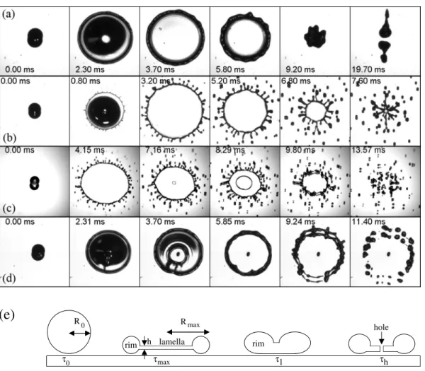
Depending on the drop radius and velocity, different be-haviors of drop impact can be observed. When We is greater than 1 and lower than a critical value for which splashing occurs, the drop spreads due to inertia, recoils and bounces because of surface tension, as depicted in Fig.1共a兲. The fea-tures共elasticity and maximal deformation兲 of such a bounc-ing process on hot plates have been extensively studied in the past.14,18 The drop reaches the shape of a thin lamella surrounded by a rim, as observed and modeled in the past 20 years.16,19,20
At higher We, satellite droplets are observed during the impact due to the destabilization of the moving edge. This splash mechanism has been studied in many situations. For inertial Leidenfrost impact, the splash threshold is set by a
critical Weber number Wec= 160, as reported in Refs.21–23 for film boiling. Our experiments are in good agreement with Wec= 150– 180.
If the impact velocity is further increased, another mechanism that can also result in drop fragmentation ap-pears, namely, the formation of a hole in the lamella, as depicted in Fig.1共c兲. During spreading, the liquid sheet de-stabilizes and dewetting is observed. The receding outer rim and the expanding hole front then collide, resulting in the formation of a torus upward, which destabilizes in many sat-ellite droplets, as depicted in Fig.1共c兲. Our present purpose is to further characterize this hole forming and expanding phenomenon so as to predict in which conditions it proves relevant for drop fragmentation, as compared to splash.
To achieve such a goal, we first concentrate on the con-ditions for hole formation by comparing the timescales in-volved both in the impact process and in the hole formation. Concerning the characteristic timescale associated with the impact process, it is expected to be set, for a bouncing drop on a smooth substrate, by a balance between surface tension and inertia.21,24Consequently, we anticipate it to scale as the oscillation period osc of the impacting drop in air, where
oscreads
TABLE I. Properties of the liquid employed during experiments. Boiling point共bp兲 and Leidenfrost point 共Lp兲 are given in °C. Surface tension␥and densityvalues are evaluated at the boiling point.
bp Lp 共kg/m3兲 共mN/m兲␥ Isopropanol 82.5 165 710 16 Acetone 56 140 750 21.2 h R τ τ τ τ Rmax max 0
(e)
0 lamella l h hole rim rimFIG. 1. Image sequence of the impact of isopropanol drop on a silicon wafer. 共a兲 Complete rebound on a smooth substrate R0= 1 mm and
We= 170.共b兲 Splash on a smooth substrate at R0= 1 mm and We= 260.共c兲 Splash and hole formation at the center of impact on a smooth substrate at R0 = 1.3 mm and We= 390.共d兲 Hole formation without splash on a defect of size d=400 m sintered on the substrate, R0= 1 mm and We= 170.共e兲 Cross
section scheme of the impact and hole formation processes.
osc=
冑
R03␥ . 共2兲
Experimentally, the time max to reach the maximum
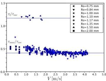
diam-eter after contact provides one such typical time associated with the drop impact. Figure 2 reports the measured max,
scaled byosc, for different drop sizes and velocities. In line
with the above analysis, this spreading time max indeed
scales essentially as osc, with max/osc⬇0.41 on a wide
range of impact velocities. Note, however, the slight devia-tion from this behavior observed at low velocity, similar to what was previously described experimentally25 for contact time. These results are in good agreement with observations on superhydrophobic substrate as discussed in Ref.18, sug-gesting no important effect of dynamic surface tension.
Parallel to the spreading time, the lamella lifetimel, the time for the lamella to close on itself after spreading and recoil关see Fig.1共e兲兴, yields another natural way to quantify the typical time associated with the impact. Practically,lcan be measured as far as the lamella exists共high enough impact velocity兲 and that no hole is formed, thus restricting the ac-cessible parameter range. Measured lifetimelis reported in Fig.2, where it appears independent of the impact velocity in agreement with the expected scaling by osc. Overall, the lifetime simply readsl⬇1.17osc.
We now turn to the characterization of the relevant time-scale associated with the hole formation on smooth substrate. The latter is naturally measured as the timehto nucleate a hole in the lamella, as reported in Fig.3 for different drop radii and velocities. Overall,h increases with R0, and
de-creases with V, thus showing a velocity dependency unlike the previous drop impact typical time. As a consequence, if the impact velocity is below a critical value Vc, discussed hereafter,hbecomes larger thanl, and therefore no hole is formed.
We observe that on a smooth surface, this critical veloc-ity is always larger than the threshold velocveloc-ity for classical splash, which then appears as the relevant mechanism for drop fragmentation on defect-free surfaces. However, the
situation can be strongly modified on real surfaces with finite roughness. As shown below, the hole formation is indeed very sensitive to the presence of a microscopic defect which can trigger its appearance and shift it toward lower impact velocity. It thus makes the liquid lamella rupture by hole growth the relevant mechanism for satellite droplet formation.
Experimentally, a single model-defect is used to achieve quantitative insight into this process. It consists of a 30– 300 m spherical glass or borosilicate bead that is sin-tered onto a smooth silicon wafer.
More precisely, a defect of selected diameter is with-drawn from a bench of polydisperse beads dispersed onto a rough hydrophobic substrate with an atomic force micro-scope cantilever. Electrostatic and van der Waals interactions are restricted with the hydrophobic substrate intrinsically; therefore, the bead remains attached to the cantilever and is then gently dropped off on the smooth silicon wafer. After deposition, it is heated at 700 ° C for 2 h, allowing a smooth sintering. Bead size and circularity have been measured by profilometry and optical microscopy.
Now, as already stated, when a drop impacts near such a defect, the formation of a hole in the lamella happens earlier and at lower impact velocity共compared to defect-free sub-strate兲 and takes place on the defect, as shown in Fig.1共d兲. Such hole formation at the defect could result from different possible mechanisms such as bubble entrapment at the de-fect, or nucleate boiling at the—presumably cooler—tip of the protruding defect. The important point here, however, is that in both cases the size of the defect fully determines the size of the induced hole. It acts as a puncturing object of set dimensions, thus imposing conditions on film characteristics for hole opening26 共see details hereafter兲.
As before, the typical timescale associated with the hole formation is characterized experimentally by measuring the elapsed timehat which a hole in the lamella appears. The inset of Fig. 4 shows the measured h as a function of the distance x that separates the bead and the center of impact, for fixed defect and drop sizes, and impact velocity. This time appears essentially constant up to a distance of 0.5Rmax
FIG. 2. 共Color online兲 Impact on a smooth substrate. Time to reach the maximal diametermaxand lifetime of the lamellalnormalized byoscvs
impact velocity for several drop radii.
FIG. 3.共Color online兲 Impact on a smooth substrate. Timehto nucleate a
and from now on,h is taken as the value of this plateau. From there, we can concentrate on the measured values of the timehfor hole formation as a function of impact veloci-ties V, drop radii R0, and defect diameters d. Figure4reports
this timeh versus V−1 for several drop radii R0 and defect
diameters d.h is a decreasing function of V and d.
As for the timescale associated with drop impact, for which a scaling inoscwas evidenced, we now need to relate the timeh for hole formation to the different physical pa-rameters of the problem. This requires additional description and characterization of the liquid sheet dynamical properties, a task for which the examination of the—subsequent— growth of the lamella hole proved fruitful. The latter indeed expands due to surface tension and is found to remain nearly circular throughout expansion 共aspect ratio between 1.0 and 1.1兲.
Two distinct parameters are then accessible experimen-tally: the variations of the hole radius with time, yielding a growth velocity Vh= dr/dt, and the drift velocity of the hole center. The latter is a consequence of the hole advection by the flow in the lamella along the radial coordinate. In the first approximation, we thus identify the center drift with the ve-locity Vl of the liquid in the lamella. This drift velocity is found essentially constant during hole opening, and the de-duced Vl is reported in Fig. 5 versus the impact velocity. Overall, a linear dependency is observed. Hence, at this level of description, we retain that Vl⬃V.
Now, examining the hole growth dynamics, we show that the radius of the opening hole r increases linearly with time, as reported in the inset of Fig.6, in agreement with a constant dewetting velocity. This is reminiscent of the well-known inertial dewetting of a liquid sheet of thickness h,27,28 whose front velocity writes
冑
2␥/h. As already mentioned, we expect here the puncturing defect size to set the film characteristics h of hole formation 共opening兲. Indeed, plot-ting Vhversus defect size d in Fig. 6 shows a very good fit with Vh⬇2冑
2␥/d. This corresponds to a critical lamella thickness for a hole growth of h = d/4. This is in fullagree-ment with the expected size threshold, in nonwetting situa-tion, for hole expansion in a liquid lamella.26 Here, in prac-tice, the hole created at the defect does not grow, until when the lamella has thinned down to the critical thickness.
As shown in the right inset of Fig.6, the hole-opening velocity appears to be independent of the position of the defect x, which suggests that the lamella reaches a uniform thickness. If so, it is straightforward that, from the volume conservation in the expanding lamella, the fluid velocity should decrease with the radial position. Thus, it is clear that retaining a “mean” lamella velocity Vl⬃V, as presented above, only constitutes a first step modeling. A more detailed determination of Vl with time and position is a route for future investigations beyond this global description.
Thus, at first approximation, here we assume a constant velocity in the lamella of uniform thickness. The radius of the slab increases with time as R = Vlt, if we do not take into account the rim. This approximation has already been shown
FIG. 4. 共Color online兲 Time of formation of the hole hafter impact for
several drop radii R0and defect diameters d vs V−1. Inset: time to nucleate a
holehvs the radial coordinate x for an impact velocity of V = 2.4 m/s, a
drop size R0= 1.46 mm, and a defect size d = 290 m.
FIG. 5. 共Color online兲 Velocity of the lamella Vl vs impact velocity
共R0= 1.5 mm, d = 77 m兲.
FIG. 6.共Color online兲 Dewetting velocity of the hole Vhvs defect size d.
The dashed blue line corresponds to the fit Vh= 2冑2␥/d. Insets:共a兲 radius
of a hole nucleated on a defect of size d = 290 m, R0= 1.46 mm;共b兲 open-ing velocity of the hole Vh on a defect vs the position of the defect x
共d=107 m, R0= 1.46 mm兲.
successfully in the past.29 The global volume conservation reads hR2=43R03or h = 4R03/3Vl
2
t2. The hole will be formed for h⬇d/4 after a time h,
h=
冑
8 3 2R03 d 1 Vl . 共3兲 With Vl⬃V, h/osc⬃ Vd V, 共4兲where Vd=
冑
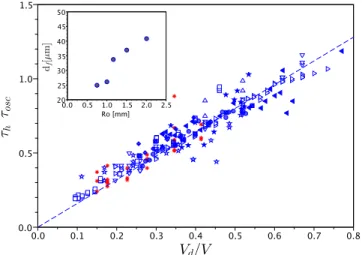
2␥/d is the dewetting velocity in a lamella of thickness d. The hole formation time versus V−1 for severaldrop radii and defect sizes is reported in Fig. 4. A linear dependency with 1/V is observed as expected from Eq.共4兲. Moreover, the lamella rupture time appears to be shorter when the defect size is increased. It indicates that the larger the defect, the earlier the formation of the hole. More quan-titatively, Fig. 7 compares the scaled hole formation time
h/osc with the inverse of the scaled velocity Vd/V. The experimental data plotted in Fig. 4 collapse on the model curve defined by Eq.共4兲.
A criterion for hole formation on a defect of size d can then be defined: the hole is formed ifh is smaller than the lifetime of the lamellal⬇1.17osc. This conditions allows
us to define a critical impact velocity Vc⬇ 1.4
冑
2␥
d, 共5兲
which is independent of the drop radius R0, and of the order
of 0.9 m/s for a 100 m defect for isopropanol drops. Before discussing the importance of this hole-opening process for drop fragmentation, it is interesting to reconsider the smooth surface case within the present framework. In-deed, the data reported in Fig.3collapse well on the master curve of Fig.7if a fictive defect of size dfis introduced. The inset of Fig. 7 reports such df values yielding best data collapse as a function of R0. As can be seen, it increases
almost linearly with R0, in the range of our study,
with df⬇30 m for a drop of radius R0= 1 mm. The origin
of this length remains unclear. However, some experiments13,14,16already showed that a bubble, reported to have a size of 25 m, can be trapped during the impact due to capillary wave convergence at the center of the thin film or defect in the substrate. Here, even if such a small bubble cannot be observed with our set-up, it could very well act as a defect entailing dry spot formation.
With these different elements, characterizing the hole formation and growth process, the relevancy of this mecha-nism for drop fragmentation—as compared to classical splash—can be raised. As discussed before, the critical splash velocity in our system is given by V⬎
冑
Wec␥/R0with Wec= 160. If we compare it to the threshold velocity Vc defined by Eq.共5兲, a critical aspect ratio to get hole forma-tion without splash is set by
R0
d ⬇ 40. 共6兲
With the development of nanodroplets and nanoprinting, this phenomenon gives a limit for surface roughness relevancy in the phenomenon at stake. For example, surface defects of 10 nm could induce hole formation during the impact of a 1 m droplet intrinsically.
In practice, the fragmentation is the consequence of the collision of the expanding dry spot edge共inner rim兲 with that surrounding the receding slab共outer rim兲. But it occurs only when the effect of the collision is maximized, i.e., when both rims have comparable momentum. Thus, the velocity crite-rion associated with the sole hole nucleation 关Eq.共5兲兴 does not necessarily warrant efficient fragmentation. Since the outer rim mass is always larger than the hole edge mass, the momentum is comparable when the outer rim is almost mo-tionless. Thus, taking into account that the fragmentation would occur when the outer rim starts to recede, i.e., at t⬇max, the critical velocity for drop fragmentation is better
given by Vc
frag
= 4Vd. This entails a critical aspect ratio of 5, in better agreement with our observations关see Fig.1共d兲兴.
As a conclusion, a mechanism different from the usual splash can be responsible for the fragmentation of a drop impacting on a hot plate共i.e., in a nonwetting situation兲. For a smooth surface, the rupture spot appears at the center of the impact as if a micrometric defect共30 m for a millimetric drop兲 of some sort was present on the surface. On the other hand, the hole formation can be triggered by a defect, which acts as a rupture spot. Moreover, the analysis of hole dynam-ics provides information on thickness and liquid flow veloc-ity in the lamella for Leidenfrost impact.
Finally, the relevancy of such a mechanism compared to splash is discussed, and we show that this is the main mecha-nism of drop fragmentation, provided that defect and drop sizes are in a certain ratio. This work is a starting point in model conditions共a single defect in a nonwetting situation兲 to understand hole-induced drop fragmentation at impact, and should be generalized to various surface wettabilities and to multiple defects. The influence of a single defect on splash threshold must be studied in connection to observa-tions made for patterned substrates.30
FIG. 7. 共Color online兲 Comparison between h/max and Vd/V, and the
results of the model共solid line兲. Inset: size of the equivalent defect dfvs R0.
Symbols as in Figs.3and4.共ⴱ兲 corresponds to data obtained with acetone,
The authors thank C. Clanet and L. Bocquet for useful discussions, H. Ferret for technical help, L. Cousin for pre-liminary measurements, and A. Piednoir for bead deposition and sintering.
1D. B. van Dam and C. Le Clerc, “Experimental study of the impact of an
ink-jet printed droplet on a solid substrate,”Phys. Fluids16, 3403共2004兲.
2V. Bergeron, D. Bonn, J. Y. Martin, and L. Vovelle, “Controlling droplet
deposition with polymer additives,”Nature共London兲 405, 772共2000兲.
3A. M. Worthington, “On the form assumed by drops of liquids falling
vertically on horizontal plate,”Proc. R. Soc. London 25, 261共1876兲.
4A. L. Biance, C. Clanet, and D. Quere, “Leidenfrost drops,”Phys. Fluids
15, 1632共2003兲.
5A. L. Biance, “Gouttes inertielles: De la caléfaction à l’étalement,” Ph.D.
thesis, Université Paris 6, 2004.
6A. L. Yarin, “Drop impact dynamics: Splashing, spreading, receding,
bouncing,”Annu. Rev. Fluid Mech. 38, 159共2006兲.
7P. Tsai, S. Pacheco, C. Pirat, L. Lefferts, and D. Lohse, “Drop impact upon
micro- and nanostructured superhydrophobic surfaces,” Langmuir 25,
12293共2009兲.
8L. Xu, W. W. Zhang, and S. R. Nagel, “Drop splashing on a dry smooth
surface,”Phys. Rev. Lett. 94, 184505共2005兲.
9C. Josserand, L. Lemoyne, R. Troeger, and S. Zaleski, “Droplet impact on
a dry surface: Triggering the splash with a small obstacle,”J. Fluid Mech.
524, 47共2005兲.
10L. Xu, “Liquid drop splashing on smooth, rough, and textured surfaces,” Phys. Rev. E 75, 056316共2007兲.
11R. E. Pepper, L. Courbin, and H. A. Stone, “Splashing on elastic
mem-branes: The importance of early-time dynamics,”Phys. Fluids 20, 082103
共2008兲.
12R. Dhiman and S. Chandra, “Rupture of radially spreading liquid films,” Phys. Fluids 20, 092104共2008兲.
13S. T. Thoroddsen, K. Takehara, and T. G. Etoh, “Dewetting at the centre of
a drop impact,”Mod. Phys. Lett. B 23, 361共2009兲.
14S. Chandra and C. T. Avedisian, “On the collision of a droplet with a solid
surface,”Proc. R. Soc. London, Ser. A 432, 13共1991兲.
15N. Z. Mehdizadeh and S. Chandra, “Boiling during high velocity impact
of water droplets on a hot stainless steel surface,”Proc. R. Soc. London, Ser. A 462, 3115共2006兲.
16R. Dhiman and S. Chandra, “Rupture of thin films during droplet impact,” Proc. R. Soc. London, Ser. A 466, 1229共2010兲.
17V. Vazquez, E. Alvarez, and J. M. Navaza, “Surface tension of alcohol
+ water from 20 to 50 ° C,”J. Chem. Eng. Data 40, 611共1995兲.
18A. L. Biance, F. Chevy, C. Clanet, G. Lagubeau, and D. Quere, “On the
elasticity of an inertial liquid shock,”J. Fluid Mech. 554, 47共2006兲.
19I. V. Roisman, E. Berberovic, and C. Tropea, “Inertia dominated drop
collisions. I. On the universal flow in the lamella,” Phys. Fluids 21,
052103共2009兲.
20J. Eggers, M. A. Fontelos, C. Josserand, and S. Zaleski, “Drop dynamics
after impact on a solid wall: Theory and simulations,”Phys. Fluids 22,
062101共2010兲.
21L. H. Wachters and N. A. Westerling, “Heat transfer from a hot wall to
impinging water drops in spheroidal state,”Chem. Eng. Sci. 21, 1047
共1966兲.
22M. Bussmann, S. Chandra, and J. Mostaghimi, “Modeling the splash of a
droplet impacting a solid surface,”Phys. Fluids 12, 3121共2000兲.
23K. Range and F. Feuillebois, “Influence of surface roughness on liquid
drop impact,”J. Colloid Interface Sci. 203, 16共1998兲.
24D. Richard, C. Clanet, and D. Quere, “Surface phenomena—Contact time
of a bouncing drop,”Nature共London兲 417, 811共2002兲.
25K. Okumura, F. Chevy, D. Richard, D. Quere, and C. Clanet, “Water
spring: A model for bouncing drops,”EPL 62, 237共2003兲.
26G. I. Taylor and D. H. Michael, “Making holes in a sheet of fluid,”J. Fluid Mech. 58, 625共1973兲.
27G. I. Taylor, “The dynamics of thin sheets of fluid. 3. Disintegration of
fluid sheets,”Proc. R. Soc. London, Ser. A 253, 313共1959兲.
28F. Culick, “Comments on a ruptured soap film,”J. Appl. Phys. 31, 1128
共1960兲.
29C. Clanet, C. Beguin, D. Richard, and D. Quere, “Maximal deformation of
an impacting drop,”J. Fluid Mech. 517, 199共2004兲.
30M. Reyssat, D. Richard, C. Clanet, and D. Quéré, “Dynamical
superhy-drophobicity,”Faraday Discuss. 146, 19共2010兲.