HAL Id: hal-02470650
https://hal.archives-ouvertes.fr/hal-02470650
Submitted on 24 Feb 2020
HAL is a multi-disciplinary open access archive for the deposit and dissemination of sci-entific research documents, whether they are pub-lished or not. The documents may come from teaching and research institutions in France or abroad, or from public or private research centers.
L’archive ouverte pluridisciplinaire HAL, est destinée au dépôt et à la diffusion de documents scientifiques de niveau recherche, publiés ou non, émanant des établissements d’enseignement et de recherche français ou étrangers, des laboratoires publics ou privés.
Tatiana Aubonnet, Ludovic Henrio, Frédéric Lemoine, Eric Madelaine,
Noëmie Simoni
To cite this version:
Tatiana Aubonnet, Ludovic Henrio, Frédéric Lemoine, Eric Madelaine, Noëmie Simoni. Livrable D1.2.2 Modèle avancé QoSaware. [Research Report] Conservatoire national des arts et métiers -CNAM. 2015. �hal-02470650�
Date prévue Date livraison 30/09/2015 30/09/2015 Nature Public
Statut Final Version 01
Propriétés du Document
Source du Document FSN OpenCloudware
Titre du Document Livrable L1.2.2 - Modèle avancé QoS-aware
Module(s) SP1.2
Responsable TPT
Auteur(s) / contributeur(s) Tatiana Aubonnet
1,3, Ludovic Henrio2, Frédéric Lemoine3, Eric Madelaine4, Noëmie Simoni1
Affiliations 1 : 2 : UNS, Télécom Paristech, CNRS LTCI-UMR 514 CNRS, UMR 7271, Sophia-Antipolis France
3 : CNAM, CEDRIC-ROC
4 : Inria, UNS, CNRS, UMR 7271, Sophia-Antipolis France
Statut du Document Final
Version 1.0
Date de la validation 2015-09-30
Résumé
Cloud computing and Future Internet promise a new ecosystem where everything is "as a service", reachable and connectable anywhere and anytime, everyone succeeding to get a service composition that meets his needs. But do we have the structure and the appropriate properties to design the service components and do we have the means to manage, at run-time, the personalized compositions corresponding to Service Level Agreement ? In this article we introduce an entity of service composition called Self-Controlled Component (SCC), including, since the design step, functional and non-functional specifications. SCCs benefit both from the strong structure, explicit composition, and autonomic management of component-oriented programming, and from the highly dynamic composition, and discovery capacities of service-component-oriented computing. Self-control mechanisms are then attached automatically to SCCs to enable autonomic application management during execution. The objective of this new concept is to provide strong Quality of Service (QoS) guarantees of composed applications. We illustrate the approach using an example called Springoo, to how in the context of a legacy application the contributions and benefits of our solution. For the management of the service composition we propose the concept of Virtual Private Service Network (VPSN) and Virtual Service Community (VSC) that allows us to model the personalised Service Level Agreement (SLA) where user requirements and provider offers converge on a QoS contract.
Mots Clefs
Service component, quality of service, autonomic control, service composition
1 Objectif et introduction 3
2 Background 4 2.1 Related Work . . . .. . . 4
2.1.1 From component models to service models . . . . . . 4
2.1.2 Autonomic management . . . .. . . . . . .. . . 6
2.1.3 Positioning . . . .. . . . . . .. . . . 7
2.2 GCM . . . .. . . . . . 7
2.3 Modelling/design platform . . . . . . . . . 7
2.3.1 The VerCors modelling tool-set . . . .. . . . . . . . . 7
2.3.2 Behaviour specification and verification . . . . . . .. . . 8
3 Self-controlled service component 9 3.1 Properties . . . 9
3.2 Membrane structure . . . .. . . 10
3.3 The monitoring component (MaaS) . . . 10
Date prévue Date livraison 30/09/2015 30/09/2015 Nature Public
Statut Final Version 01
3.5 Interfaces . . . .. . . 12
4 Service composition management 13 4.1 Service composition : the VPSN . . . .. . . . . . 13
4.2 Operational decisions : VSCs and SCCs on the VPSN . . . .. . . . . . 13
4.2.1 VSC creation . . . . . . .. . . .. . . 14
4.2.2 Dynamic reaction of SCCs on the VPSN . . . . . 14
4.3 Resource management . . . . . . . . . 16
4.3.1 Assumptions . . . .. .. . . . . . 16
4.3.2 Anticipating the interruption of the service session . . . .. . . . . . 16
4.3.3 Management based on Communities of Interest . . . . . . . . . . . . 17
4.3.4 Cross-organizational distributed Management . . . .. . . . .. . . .. . . . . . 17
4.3.5 Management of Virtual Communities . . . . . . . . . 18
4.4 Tactical decision . . . . . . .. . . 20
4.5 Strategic decision . . . 20
5 Application design with autonomic control 20 5.1 Composing SCC components . . . .. . . 22
5.2 Using non-SCC components . . . .. . . 22
5.3 Global autonomic control : the MAPE loop . . . . . . . . . 22
6 From SCC component to SLA 23 6.1 Approach . . . . . . 23
6.2 Service Level Objective . . . . . . 24
6.3 Service Level Agreement . . . . . . 24
7 The Springoo use-case 25
8 Experiments 27
9 Conclusion 28
1
Objectif et introduction
The objective of this deliverable is to present the efforts done in SP1.2 to design QoS-aware adaptive components for Cloud applications. In this work we focus on the design of a component framework for Cloud applications with a guaranteed QoS. Indeed, a cloud application can be de-signed from components offered in a catalog interconnected adequately. This approach enables the nearly automatic creation of solutions corresponding to the user’s demand.
The originality of this deliverable is that it presents a solution for the guarantee of quality of service through elasticity and adaptation in a fully automated manner. The solution relies on ideas taken from service oriented computing and from software components. The new composition model is somehow more restricted than stateful control-flow sensitive components ; but this is the price to pay for automatic composition and adaptation. Finally our component applications feature at the same time QoS guarantees provided by the automatic composition and adaptation solution, and safety guarantees thanks to the software verification tools existing for GCM/ProActive.
One of the slogans of cloud computing is “to pay-as-you-go”. It means that the supplier is able to adapt to the user’s needs. His ability to manage the elasticity, the high availability, and the on-demand provisioning is a part of his offer. The integration, from the design phase, of automated management procedures is always desirable, but it is even more crucial in the competitive context of this new ecosystem. From the cloud provider point of view, the objective is to meet the required properties based on customer requirements and needs. In practice, many cloud providers offer the same services that differ in their quality of service levels, price, and in the way they are created, deployed, and managed.
As a consequence, the request and the offer must be entirely and explicitly guaranteed by the Service Level Agreement (SLA). The questions are : (i) how to adapt the component models in order to ensure the convergence of supply and demand ? (ii) how to ensure both the autonomy of each component and the end-to-end quality of the service ? and (iii) what to record into the SLA to ensure its practical usability and its veracity ?
(i) For converging supply and demand, one would have to choose components "as a Service", the user must pick the services corresponding to the behaviour and the quality of service he expects. Moreover, the service composition should facilitate their adaptation on demand, it should reduce the functional dependencies between services, and have loose bindings between entities of the com-position as Service Oriented Architecture (SOA) advocates. Indeed, without these loose ties the composition cannot be customized and the interconnection of components cannot vary on demand. (ii) Concerning guarantees, we need the right information at the right place in order to take the desired decisions. It is not enough for the service composition to be agile at functional level, but it must also be agile and dynamic at management level, i.e. at the non-functional level. In more details, the management and the SLA guarantees should be made hierarchical and distributed among services ; part of the adaptation decisions should be taken locally, but other parts must be taken from a global point of view. The structured composition and service management we present in this paper allows for a precise control of the place where decisions are taken and enacted. This enables dynamic and precise adaptation of service composition by providing the means to react at different levels when the service does not fulfill his contract.
(iii) Concerning the SLA definition, requirements, resources provided and penalties for breach of contract are to be recorded. It must be expressed in a vocabulary understandable by different parties. While the service is expressed when the service is made available, it is difficult to ensure the exactitude of the SLA, but our approach allows us to monitor the service out of contract and exclude them from the compositions.
This deliverable provides a composition framework that transforms the user-defined choices (demand) into the right services (offer) and that adapts automatically this composition at run-time. The approach we advocate allows a personalized and automated composition of services with service level guarantees accordance with SLA. Our main contributions are the following :
– We define service components that at the same time provide the guarantee of a certain service level and enable autonomic adaptation of the composition to ensure that this service quality will be guaranteed during the application execution.
– We provide an architecture for composing services featuring service discovery and SLA-based adaptation.
– We design generic Quality of Service (QoS) components guaranteeing that the service compo-sition will provide the predefined functionality and QoS. This is realised by the definition of a Virtual Private Service Network (VPSN) defining the user’s application and then, based on this description, choosing and replacing at runtime the services involved in the composition. – Those contributions are provided in a programming and execution environment that offers
ease of programming, location and distribution transparency, and autonomic adaptation. Structure of the document In this document we first present the global background for this work in Section 2. This section include related works, and a presentation of the two previous works of the partners the most crucial for the understanding of this deliverable : the GCM component model and the Vercors design and verification platform. This deliverable proposes an approach to compose components “as services” which can be self-controlled ; such components are called Self-Controlled service Component (SCC). Section 3 presents SCCs, their structure, their monitoring capabilities, and the components they embed for checking contract compliance. A solution for service composition and its adaptation is then proposed in Section 4. It relies on the notion of VPSN introduced above, on the adequate management of ressources and on a MAPE loop that controls the autonomic adaptation of the composition. Section 5 focuses on more practical and technical aspects on the creation, design and adaptation at runtime of this new kind of applications. Section 6 presents a SLA model adapted to our framework and explains how to offer Service Level Objective (SLO) and SLA based on SCC. Finally, Section 7 applies the approach we advocate to the Springoo use-case and Section 8 presents a prototype implementation of this use-case. We conclude in Section 9.
2
Background
In this section we present our background for a QoS-aware advanced model based on our self-controlled components.
In the first, we will give our related work and positioning (Section 2.1). Secondly, we present the Grid Component Model (GCM) targeting specifically cloud distributed application (Section 2.2). Finally, Section 2.3 describes the VerCors platform that we use for the modelling and behaviour analysis of our self-controlled components
2.1 Related Work
First, in the OpenCloudware project, we worked on the Fractal component (Document L1.2.1). The strengths, in addition to the functional component and the membrane, are located at the levels of management and control interfaces. Then, to enrich the membrane of the component, we turned to the GCM component, giving the possibility to include managers that meet the autonomic vision (Section 2.1.2). The "as a service" of the cloud led us to consider the SCA model (Section 2.1.1) to characterize the proposed self-controlled component and to describe the behavior of our components with the generic QoS model. This description will provide an architecture to integrate actions and decisions related to the control and management. Finaly, we present the positioning of our works (Section 2.1.3).
2.1.1 From component models to service models
Component models provide a structured programming paradigm, and ensure a very good re-usability of programs. In component applications, dependencies are defined together with provided functionalities by the means of provided/required ports ; this improves the program specification and thus its re-usability. We focus here mostly on hierarchical component models because they make the design of large-scale systems easier. A component model is said to be hierarchical if the composition of several components is also a component that can be used at a higher composition
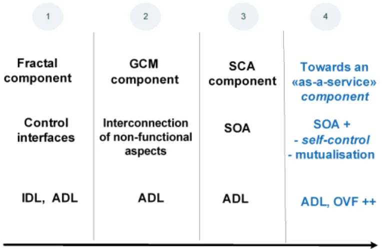
Figure 1: From component models to service models
level. We call primitive components the leaves of the composition tree, i.e. the components that contain the business code.
There are several components models permitting an assembly, which better reflects a distributed application. These are the components : Fractal, GCM (Grid Component Model) and SCA (Service Component Architecture).
Fractal [6] is a general component model, which is intended to implement, deploy and manage complex software systems. It showed its effectiveness in the particular setting of operating systems and middleware, through the use of interfaces (usage, control and management) (Figure 1 - bullet 1).
We could exploit the non-functional aspects of the Fractal model which are exposed as the component interfaces. Nevertheless, it is impossible to connect to these interfaces, since they have to be invoked directly, and there is no support in the model to compose the non-functional aspects together : all are implemented directly at the component level.
That is why we choose the GCM component model (Figure 1 - bullet 2) that allows us to : – Define a component having a structure for the non-functional parts of the membrane as an
assembly of components.
– Build an interconnection model for the non-functional aspects.
SOA promotes a different composition pattern based on loosely coupled services ; which is a crucial property for a personalized service session. Service Component Architecture (SCA)[26] and WS (Web Services) are major approaches supporting SOA.
SCA is a component model adapted to Service Oriented Architectures (Figure 1 - bullet 3). It enables modeling service composition and creation of service components. Numerous platforms implement the SCA model, like Tuscany, Newton, or FraSCAti. The main SCA properties are : interconnection, autonomy, loose coupling, and reuse. However, the SCA model is focused on static description of components and does not standardise the runtime evolution of applications.
WS [14] is the technology supporting the flexible composition [34] , the “Mashup” [20, 22] and the methods of integration services in Cloud Computing [17, 33, 21]. WS allows the implementation of SOA recommendations, it supports Web Services Description Language (WSDL) as a description language, communication APIs like Simple Object Access Protocol (SOAP) and Representational State Transfer (REST), and coordination of services through Business Process Execution Language (BPEL) [5]. Though quite exhaustive, none of these technologies offers strong support for non-functional features like non-non-functional management and quality of service. Service coupling is also too tight to allow true dynamic service evolution : WS offers no particular support for the replace-ment of a service by another one at the middle of the execution of the application.
However, the SCA model is not dynamic because it does not allow, at runtime, dynamically adding or removing components and changing bindings. The SCDL (Service Component Definition
Language) file is designed at design time and can not be changed during the execution of the application. Therefore, changes in the composition of the services require to stop the application and restart it to use a new composition. Dynamic reconfiguration and other non-functional aspects are not processed by the SCA specifications. It is at the implementation of the runtime support to provide such functionalities. For example, the FraSCAti platform offers the Fractal controllers providing the access API to the MAPE loop and enabling the deployment of components. The platform does not allow hot loading, which prevents the continuous design of components.
To solve this problems, we propose an “as a service” component adding the properties of self control and mutualisation to those advocated by SOA, we called SOA+ (Figure 1 - bullet 4).
Indeed, Fractal/CMG/SCA brings a strong structuration allowing expression of the composition, but at this stage, we have no notion of contract that could help in the management of SLA. Furthermore, the recommendations at the SLA level do not have the notion of service composition. That is why we are moving towards a component facilitating the design and implementation of self-controlled service we describe in the section below and used in a SLA (Section 6).
2.1.2 Autonomic management
In distributed systems and especially in the Cloud, the ability to modify at run-time execution parameters but also the architecture of the application paves the way for the autonomic adaptation of applications. In distributed systems in particular, dynamic adaptation is even more important, as the structure of components can also be used at run-time to discover services and use the most efficient service available.
Some component models and their implementations keep a trace at run-time of the component structure and their dependencies. Knowing how components are composed and being able to modify this composition at run-time provides great adaptation capabilities : the application can be adapted to evolutions in the execution environment, by changing some of the components taking part in the composition or changing the dependencies between the involved components. We call reconfiguration the actions consisting in changing at run-time the component structure, by adding or removing components in the system or by changing the way components are bound together. FraSCAti [27] is an implementation of the SCA model built upon Fractal, somehow close to GCM. It provides dynamic reconfiguration of SCA component assemblies, a binding factory, a transaction service, and a deployment engine of autonomous SCA architecture.
Additionally, if components are structured in a hierarchical manner, the adaptation can be rea-lised in a modular manner, where each (service) component is responsible for its own adaptation and for its own quality of service ; while interacting with its sub-components, or its external services for distributing the adaptation process. A deeper study of the interplay between hierarchical com-ponent models and their reconfiguration can be found in [16] which illustrates the relation between reconfiguration and hierarchy in the context of the SOFA2.0 component model.
Autonomic adaptation rules are often expressed as event condition action rules like in Automate [24] or Safran [10]. More generally, the adaptation procedure can be structured as a Monitor-Analyse-Planning-Execute (MAPE) loop for autonomic computing [18, 13]. GCM provides a framework for structuring the elements of the MAPE loop (Monitoring, Analysis, Planning, Execution) as components embedded with the management part of the components.
However those approach relies on a tight coupling between components, and components must exactly correspond to one physical entity. In service oriented architectures that can be cross-organizational, and that rely on service discovery and interchangeability, some additional effort has to be made to integrate the autonomy of each service into autonomic loosely coupled applica-tions. In this paper we show how to address this challenge and guarantee the QoS requested by the user when choosing the service. This will be done by an approach that integrates in a single entity the notion of component and the notion of interchangeable services.
2.1.3 Positioning
On one side SLA and contracts for services already exist [19, 31, 32] but they lack the compo-sitional design and management featured by components. On the other side components are very compositional and expressive, but the support for SLA, in the specific context of service-oriented components, is very weak. Our proposal presented in this paper is to use GCM and its strongly structured entities to provide a service oriented component platform that eases the design and exe-cution of self-controlled services with SLA guarantees. In other words, our contribution is first to define service-oriented GCM components, i.e. hierarchical components restrained to service-oriented features. Relying on this model, we design specific support for SLA and contracts dedicated to these service-components. In the following We will describe our notion of SCC components that is com-ponents that can be integrated in a service-oriented approach with dedicated management features. We retain the GCM model for its membrane that comes with a high-level framework for the deve-lopment of management capabilities [9]. For dynamic management, it will be performed modularly, where each service (component) is responsible for its own adaptation and its own quality of service ; while interacting with internal or external services. A strong point of our proposal is to link the provider and the consumer of the service through a SCC based SLA.
2.2 GCM
The Grid Component Model (GCM) [8], is an extension of Fractal targeting specifically distribu-ted systems. A strong point of GCM is the separation of concerns [9]. In GCM, the membrane, i.e. the management part of the component, can be defined precisely with all necessary interconnections between management features and with the rest of the component hierarchy.
GCM/ProActive is the reference implementation of the GCM component model. It is based on the ProActive Java library [25]. It is based on the ProActive Java library and relies on the notion of active objects. It is important to note that each component corresponds at runtime to an active object and consequently each component can easily be deployed on a separate JVM and can be migrated. Of course, this implementation relies on design and implementation choices relatively to the purely structural definition provided by the GCM model. Using active objects to implement individual components is a crucial choice in the context of this work as components react to incoming requests by serving them and interact asynchronously in a loosely coupled manner. Consequently this implementation of GCM fits particularly well with the service-oriented loosely coupled vision advocated in this deliverable. In summary, GCM/ProActive is a component framework that is particularly well adapted to the implementation of SCCs.
2.3 Modelling/design platform
In this section we introduce the VerCors platform that we use for the modelling and behaviour analysis of our self-controlled components. Having a tool-supported methodology is first important for the design phase, when the designer builds his/her application, using legacy functional compo-nents as basic bricks, and assembling them following our SCC generic compocompo-nents. The toolsuite is also very useful for generating executable code containing the whole architecture description and the skeleton of the final application. We present the VerCors platform in Section 2.3.1, then discuss how to use this tool-set for formal verification of the application behaviours in Section 2.3.2. 2.3.1 The VerCors modelling tool-set
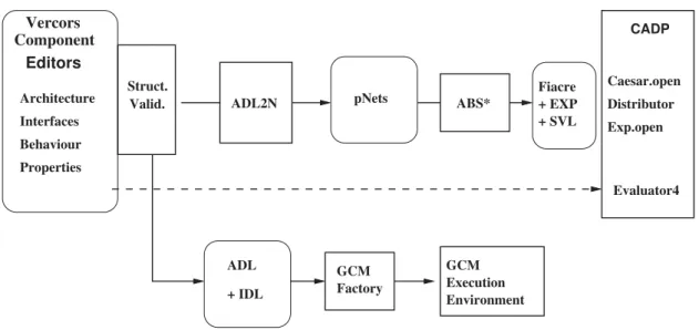
VerCors [7] is a platform for the specification, analysis, verification, and validation of GCM-based applications. The principle of the tool is illustrated in Figure 2. First, a user specifies the architecture of a GCM-based application, the signature of its interfaces, and the behaviour of the primitive components using VerCors Component Editor (VCE). Here a first validation is performed, concerning all structural coherency aspects of the application model. This check guarantees static validity of the model, and ensures also that the code generation will terminate correctly, and that the generated code will not fail during deployment of the application components. Then, from
GCM Execution Environment Fiacre + EXP + SVL CADP Evaluator4 Caesar.open Distributor Exp.open ABS* pNets ADL2N GCM Factory Struct. Valid. Component Architecture Interfaces Behaviour Properties Vercors Editors ADL + IDL
Figure 2: Principles of the VerCors platform
these descriptions the behavioural model of an application is generated (ADL2N) in a form of a dedicated behavioural semantic model : a parameterised networks of synchronised automata (pNets). This semantic model is transformed by abstraction functions (ABS*), until reaching a finite model suitable for model-checking. Finally, the Model Checker, in our case the CADP tool [12], verifies the correctness of the model with respect to a set of temporal logic properties (user requirements) and in the case errors are detected it provides their description.
Once the requirements have been proven correct on the VCE specification, the user can generate the set of files allowing the deployment of the application (Architecture Description Language (ADL) for the Architecture Description, IDL for the Interface definition in the form of Java interfaces). Then naturally, the user has to provide java classes implementing the service methods of the primitive components. These files are processed by the GCM component factory to build an executable application that is executed within the GCM/ProActive execution environment.
2.3.2 Behaviour specification and verification
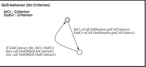
In order to generate a behavioural model in the VerCors platform, and ultimately ensure by model-checking that the overall component assembly behaves as expected (e.g. does not deadlock), the application architect should provide : 1) an architectural description, in terms of a composition of components, with their interfaces and bindings ; and 2) for each service method of a primitive components, an abstract specification of its behaviour, e.g. in the form of a Unified Modeling Lan-guage (UML) state-machine, encoding the data- and control-flow of the component assembly. The transitions of the state-machines represent the communication events between components, inclu-ding whatever data that is significant for the modelling. There is no need at this step in the design of the application to have too much detail on the real implementation ; in particular any information that is only relevant to the functional code of the components should be abstracted away. The point here is that formal verification (model-checking) is performed by essence on an abstract model, not on the real executed code. Indeed, too much details would make model-checking difficult, if not impossible. The heart of the approach (but this is far from the topic of this article) is to include in the abstract model, and here in our state-machines, only what is needed to represent the beha-viour of the application, including asynchronous communication, but also internal workflow of the service methods. The corresponding part of the code will be generated, and should not be modified by the developper, when adding the functional part of the code. In Figure 3, we give an example of the (simplified) behaviour specification of our QoSControl component. On activation, the QoS-Control component has received its contract as a parameter, that we represent here as "thr", the threshold values of the set of criteria. On a periodic basis, it will query the In and Out monitors for their respective criteria values, using the getCritValues method of the respective InMonitor and OutMonitor interfaces, and compare them with the thresholds (using the IsInContract
predi-InCr : Criterion InCr : Criterion InCr : Criterion InCr : Criterion InCr : CriterionInCr : CriterionInCr : CriterionInCr : CriterionInCr : CriterionInCr : CriterionInCr : CriterionInCr : CriterionInCr : CriterionInCr : CriterionInCr : CriterionInCr : CriterionInCr : Criterion OutCr : Criterion OutCr : Criterion OutCr : Criterion OutCr : Criterion OutCr : CriterionOutCr : CriterionOutCr : CriterionOutCr : CriterionOutCr : CriterionOutCr : CriterionOutCr : CriterionOutCr : CriterionOutCr : CriterionOutCr : CriterionOutCr : CriterionOutCr : CriterionOutCr : Criterion
QoS-behavior (thr:Criterion) QoS-behavior (thr:Criterion) QoS-behavior (thr:Criterion) QoS-behavior (thr:Criterion) QoS-behavior (thr:Criterion) QoS-behavior (thr:Criterion)QoS-behavior (thr:Criterion)QoS-behavior (thr:Criterion)QoS-behavior (thr:Criterion)QoS-behavior (thr:Criterion)QoS-behavior (thr:Criterion)QoS-behavior (thr:Criterion)QoS-behavior (thr:Criterion)QoS-behavior (thr:Criterion)QoS-behavior (thr:Criterion)QoS-behavior (thr:Criterion)QoS-behavior (thr:Criterion)
InCr:=Call InMonitor.getCritValues(); InCr:=Call InMonitor.getCritValues(); InCr:=Call InMonitor.getCritValues(); InCr:=Call InMonitor.getCritValues(); InCr:=Call InMonitor.getCritValues(); InCr:=Call InMonitor.getCritValues();InCr:=Call InMonitor.getCritValues();InCr:=Call InMonitor.getCritValues();InCr:=Call InMonitor.getCritValues();InCr:=Call InMonitor.getCritValues();InCr:=Call InMonitor.getCritValues();InCr:=Call InMonitor.getCritValues();InCr:=Call InMonitor.getCritValues();InCr:=Call InMonitor.getCritValues();InCr:=Call InMonitor.getCritValues(); InCr:=Call InMonitor.getCritValues();InCr:=Call InMonitor.getCritValues();
OutCr:=Call OutMonitor.getCritValues(); OutCr:=Call OutMonitor.getCritValues(); OutCr:=Call OutMonitor.getCritValues(); OutCr:=Call OutMonitor.getCritValues(); OutCr:=Call OutMonitor.getCritValues(); OutCr:=Call OutMonitor.getCritValues();OutCr:=Call OutMonitor.getCritValues();OutCr:=Call OutMonitor.getCritValues();OutCr:=Call OutMonitor.getCritValues();OutCr:=Call OutMonitor.getCritValues();OutCr:=Call OutMonitor.getCritValues();OutCr:=Call OutMonitor.getCritValues();OutCr:=Call OutMonitor.getCritValues();OutCr:=Call OutMonitor.getCritValues();OutCr:=Call OutMonitor.getCritValues(); OutCr:=Call OutMonitor.getCritValues();OutCr:=Call OutMonitor.getCritValues();
if IsInContract (thr, InCr, OutCr) if IsInContract (thr, InCr, OutCr) if IsInContract (thr, InCr, OutCr) if IsInContract (thr, InCr, OutCr) if IsInContract (thr, InCr, OutCr)if IsInContract (thr, InCr, OutCr)if IsInContract (thr, InCr, OutCr)if IsInContract (thr, InCr, OutCr)if IsInContract (thr, InCr, OutCr)if IsInContract (thr, InCr, OutCr)if IsInContract (thr, InCr, OutCr)if IsInContract (thr, InCr, OutCr)if IsInContract (thr, InCr, OutCr)if IsInContract (thr, InCr, OutCr)if IsInContract (thr, InCr, OutCr)if IsInContract (thr, InCr, OutCr)if IsInContract (thr, InCr, OutCr) then call OutOfQoS.InContract() then call OutOfQoS.InContract() then call OutOfQoS.InContract() then call OutOfQoS.InContract() then call OutOfQoS.InContract()then call OutOfQoS.InContract()then call OutOfQoS.InContract()then call OutOfQoS.InContract()then call OutOfQoS.InContract()then call OutOfQoS.InContract()then call OutOfQoS.InContract()then call OutOfQoS.InContract()then call OutOfQoS.InContract()then call OutOfQoS.InContract()then call OutOfQoS.InContract()then call OutOfQoS.InContract()then call OutOfQoS.InContract() else call OutOfQoS.OutContract() else call OutOfQoS.OutContract() else call OutOfQoS.OutContract() else call OutOfQoS.OutContract() else call OutOfQoS.OutContract()else call OutOfQoS.OutContract()else call OutOfQoS.OutContract()else call OutOfQoS.OutContract()else call OutOfQoS.OutContract()else call OutOfQoS.OutContract()else call OutOfQoS.OutContract()else call OutOfQoS.OutContract()else call OutOfQoS.OutContract()else call OutOfQoS.OutContract()else call OutOfQoS.OutContract()else call OutOfQoS.OutContract()else call OutOfQoS.OutContract()
Figure3: Behaviour of a QoSControl component
cate). The resulting diagnostic (InContract or OutContract) is sent on the non-functional interface OutOfQoS.
The composition of all the behaviours, together with the standard controllers of GCM, will allow the verification engine to build the full state-space of the application, and check its behavioural requirements. This construction makes use of the behavioural semantics of GCM, described in [1].
3
Self-controlled service component
Cloud computing and the future Internet promise a new ecosystem where everything would be as a service, according to a custom composition and with dynamic management of resources at run-time. Each component has the responsibility to render a service, and needs relevant information to control the business code realising this service. In this section, we first describe the properties [3] characterising SCC, as identified in the OpenCloudware project [23]. Next, we present the structure of the SCC membrane that contains the non-functional components (Section 3.2). Finally, Section 3.5 describes the interfaces of SCC components.
3.1 Properties
In this subsection we consider additional properties that characterise Cloud service component. Those properties restrict the component specification to identify the components that characterise services. For components featuring the properties exposed below, composition and adaptation are made easier, as well as the definition of the QoS featured by the SCC.
The functional component of SCC is represented in Figure 5. This is a service that must ensure the following properties (beyond properties of SCA/GCM/SOA) :
– Stateless. A SCC must not keep or handle information about its state, and the computation status. If a service maintains a state in the long-term, it will lose its property of loose coupling, its availability for other (concurrent) queries, as well as its potential to scalability. To be designed in a stateless way SCCs may delegate state management to other entities. For a service to be stateless, its operations need to be designed to make stateless treatments, i.e. the treatment of an operation should not rely on information received during a previous invocation or wait for the result of an external service invocation.
– Mutualisation. The component is a multi-tenant service component. Multiple users may require the service at the same time. This reinforces the need for the “stateless” property required above.
– Ubiquity. Service components can be gathered into communities of components that are equi-valent in functionality and QoS. Service components are defined equiequi-valent if they provide the same services with the same QoS even if their algorithms are different.
– Exposability. The functional and non-functional description of service components is provided and allows one to build an application through a catalog or a portal.
These properties allow exposing components in a library (catalog), sharing components for use in different applications, and assembling them in a personalised session.
A SCC component contains :
– A functional content (business) with the properties defined above.
– External interfaces (client and server) used for communicating with the environment. – A membrane for non-functional aspects that we describe in Section 3.2.
Ultimately, it is the responsability of the application architect to decide which components should be monitored, controlled, and subject to various levels of autonomicity, and at which level(s) of the application hierarchy the monitoring and control must be implemented. So the architecture proposed in this paper is based on templates (SCC, Monitors, etc.) that will be instanciated and specialized at design time.
3.2 Membrane structure
As we have seen in Section 2.1, in GCM components, autonomy is based on the use of a MAPE loop that we can put in the membrane of each component. But we have refined the functionality of the component to make it “as a service”. Then, we have a simple and generic MAPE loop.
Indeed, we have a single server interface and identical services for all users. In this case, checking whether a component is compliant or not to a given QoS is much simplified as the component fulfills a single service provided by a single interface.
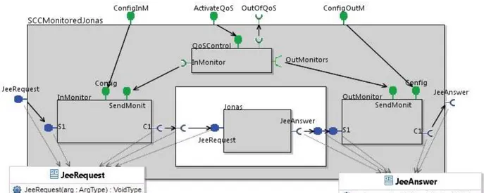
That is why we propose a “self-controlled” service component (Figure 5 shows an instanciation of an SCC for a Jonas component) based on the triad “input monitor, output monitor, and QoS control” those different parts are described below. This contract reflects behaviour defined at design time and proposed in the offer.
We also add a property to the SCC component : “QoS offered”. It will allow us to choose a service component on the basis of its behaviour (functionality and QoS).
3.3 The monitoring component (MaaS)
SCC have the goal to control contract compliance. This control should be based on measures taken at run-time. We propose in this paper to define monitoring components as “Monitoring as a Service” (MaaS). Monitoring components should be hosted in the membrane of each component.
MaaS components will introspect the component behaviour by taking measures related to the component’s behaviour. The questions that are to be answered for MaaS components are : where to measure, when to measure, and what to measure.
Where to measure ? MaaS components come in three variants, depending on their position in the data flow of the application. They are observing the external behaviour (input and/or output) of the functional component inside the SCC component (see Figures 5 and 16). They play the role of interceptors : e.g. for an input MaaS, that we call InMonitor, incoming service requests are intercepted, the interceptor component stores the non-functional information about the requests, which are then transmitted (unchanged) to the functional component, via the corresponding internal interfaces. Similarly, the OutMonitor intercepts outgoing service requests. The last case is called InOutMonitor, and is used in the case of SCC components delivering a return value on their service interface.
The use of two monitors or of a two-way monitor, will give us precise numeric values in input and output of the service. Monitor components are not responsible for metric analysis, and do not take decisions. It is the QoSControl component that will make the necessary calculations to evaluate the behaviour of the service component.
When to measure ? As a consequence of the MaaS placement, we will be able to take measures upon each request arrival and request emission.
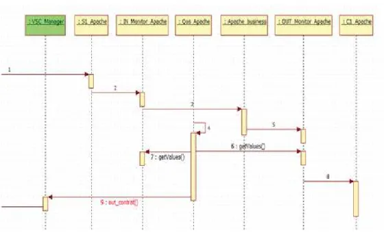
Figure 4: Sequence Diagramme of QoSControl
What to measure ? We basically propose a generic monitor that measures the number of arriving requests, the number of erroneous or rejected requests, as well as the arrival and exit time. To obtain these values we need “Counters” and “Timestamp” using the system time. More advanced monitoring functionalities could be designed to check for example the nature of the request.
3.4 Contract compliance component (QoSControl)
The QoSControl component is associated with the business component. It ensures compliance with the service contract.
QoS criteria To describe the behaviour of our components and permit homogeneous QoS mana-gement, we define a generic QoS model [2].
Four criteria are proposed to describe the QoS : availability, integrity, time, and capacity. – Availability represents the accessibility rate of the service component.
– Integrity represents the capacity to run without alteration of information (for example : error rate).
– Time represents the time required for request processing (for example : response time). – Capacity represents the maximum load the service component can handle (for example :
processing capacity).
This revealed to be useful and sufficient in all the practical cases we studied.
To support the self-management of resources, for each QoS criterion, we define three values : the design value has been determined during the design of the service, the current value is the value monitored during the service lifetime, the threshold value represents the limit the criterion should not exceed for the component to ensures the correct processing of requests.
The QoSControl process The QoSControl component checks the current behaviour of the re-source and its conformity with the contract. For this, it trigger a timer and regulary request to the monitors (InMonitor et OutMonitor) the parameters values (getValue method) according to the four criteria (Figure 4).
It compares each current value to the corresponding threshold value not to exceed. It sends an OutContract notification to the VPSN management if the current value is less (or more) than the threshold value ; in this case the dynamic management consists in replacing the failing component by an ubiquitous service fulfilling the requirements avoiding the cut of the session. Otherwise, it sends an InContract notification.
Figure 5: Structure of a Self-Controlled Component
1. The QoS requested : client side, SLO
2. The SCC QoS offered : provider side, SCC components based, QoS guaranted, corrected automaticaly by replacement of the failing component
3. The SCC QoS expected : provider side, SCC components based with adaptation mechanisms (example : add or remove component).
The QoS requested by the customer is provided by catalog components with an offered QoS and/or components with adaptation mechanisms (expected QoS). We call these last components SCC+ for "Self Controled Composition". A SCC+ component is indeed necessarily a composition. The provider responds to the client’s request (requested QoS) by establishing a user session based entirely on SCC and SCC+ components.
The behaviour specification and verification of the QosControl component are showed in Section 2.3.2.
3.5 Interfaces
We have identified 3 types of interfaces necessary to perform the self-controlled function of our SCC component : the functional, management, and control interfaces.
– Each SCC component has exactly two functional interfaces (JeeRequest and JeeAnswer, in blue, in Figure 5). One server interface includes the processing functions (service methods) that can be performed by the service component. One client interface performs invocation on the next service of the chain, transmitting its current result for further treatment or for exploitation of the final result. Note that the functions of these interfaces have no return value, according to the SCC specification.
– The management interfaces are non-functional server interfaces (ConfigInM, ConfigOutM, and ActivateQoSin green in Figure 5). They contain the necessary mechanisms to manage the configuration of non-functional components in the membrane.
– The control interface is a client non-functional interface (OutOfQoS, in green, in Figure 5). It contains mechanisms for conveying the self-control information to the Manager in charge of processing QoS violation events. It outputs InContract notifications as long as the behaviour conforms to the contract, otherwise it triggers OutContract. Absence of InContract events can be used by the manager to detect severe failures from the SCC component.
The structuring logic of the membrane allows the reusability and genericity of our components. The triad (InMonitor, OutMonitor, QoSControl) associated with each component service introduces a homogeneous service component management.
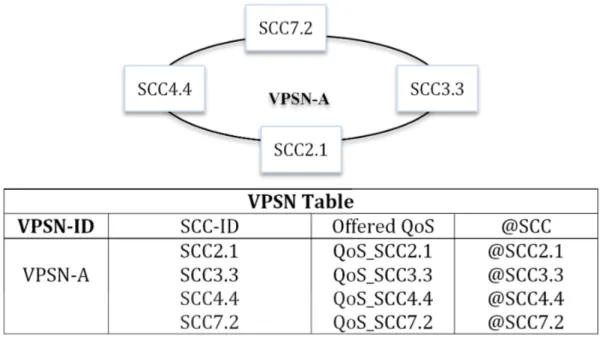
Figure 6: VPSN Table
4
Service composition management
The service composition includes different service components invoked during the user session. In a context where these components are SCCs, and in order to use service components adapted to the user demand (functionality and QoS), we propose to preselect them at the session initialisation. The pre-selection (pre-provisioning) is made according to the user required QoS mapped to the service offered QoS. This service composition constitutes the VPSN (Section 4.1). Once the VPSN is built, during exploitation phase, we need to manage the composed service. We are defining three kinds of management reactions according to the decision level : operational decisions (Section 4.2), tactical decisions (Section 4.4), and strategic decisions (Section 4.5).
4.1 Service composition : the VPSN
Based on SCC service components, upon establishment of the user’s session, a private service composition (the VPSN) is constructed by plugging together SCC components according to the functionality and the QoS required by the user (Figure 6). For each VPSN, a table is created in the knowledge base ; it contains the VPSN-ID, SCC-ID, their addresses and their offered QoS [28].
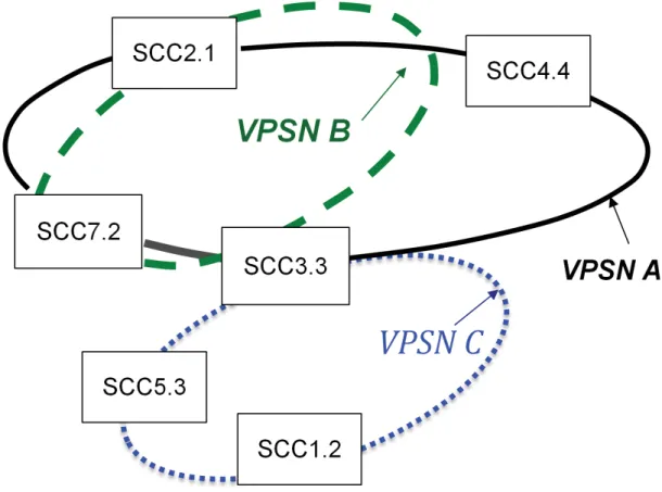
Because SCCs have the recommended properties (Stateless, Ubiquity, and Mutualisation), they can take part in multiple VPSNs simultaneously (shared by different users). For example in Figure 7, SCC3.3 component is attached to VPSN-A, VPSN-B, and VPSN-C.
In the next subsection, we will focus on the management based on information reported by the various monitors.
4.2 Operational decisions : VSCs and SCCs on the VPSN
The QoS control integrated to each SCC service component allows us to manage contract viola-tions (Out-Contract) when they occur : it takes the appropriate operational decisions. We advocate a substitution with an SCC ubiquitous service component. The component replacement is managed by using Virtual Service Communities (VSCs). A VSC is a community of components containing several equivalent SCC components (having the same functionality and the same QoS).
The community of interest concept (VSC) allows us to react dynamically to any contract vio-lation, to compute the adequate changes to be undertaken, and then to apply the changes in the VPSN. First, we describe the VSC creation (Section 4.2.1), and then we explain the dynamic reac-tion of SCCs on the VPSN (Secreac-tion 4.2.2).
Figure7: Service Mutualisation and VPSN
4.2.1 VSC creation
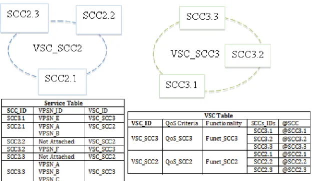
VSCs are created during service components deployment. When a service component is deployed, the information related to this service is saved in a Service Table. This information contains the SCC-ID, Functionality and QoS criteria. According to this created Service Table, the SCC is attached to the VSC corresponding to it in terms of QoS and functionality. Adding the SCC-ID in the VSC Table and adding the VSC-ID in the Service Table makes this attachment (Figure 8). In the case where no VSC corresponding to this SCC, it creates a new VSC to the deployed service ; which correspond to a VSC Table with following information VSC-ID, QoS criteria, Functionality, SCCs-IDs and SCC address. The VSCs can be grouped per strategic location, per operators or per platforms in order to fulfill user’s requests. After explaining the creation phase of VSCs, we move to the management phase.
After explaining the creation phase of VSCs, we move to the management phase. 4.2.2 Dynamic reaction of SCCs on the VPSN
Each platform will have its VPSN Management. The VPSN Management has three main actions : Replace, Add or Remove Component. These actions will be solicited according to the decision rules set by the platform of the provider.
During service exploitation, when an SCC component has a change in on or more of its four QoS criterion (Reliability, Availability, Capacity and Time) it sends an OutContract. The VPSN Management receives and reacts to this notification according to the changed QoS criterion. For example, if the OutContract results from an error rate exceeding the threshold or if the component is unavailable, then the VPSN Management replaces the component in all VPSNs to which it is attached. In our example SCC2.1 is replaced by SCC2.2 in the VPSN-A (see Figure 9). The SCC2.1 component is also part of VPSN-B (see Figure 7), so it will be replaced by an ubiquitous one (SCC2.2). If the OutContract is the result of a low capacity compared to the demand then the VPSN Management will add an ubiquitous component to cover the demand. In case where the load of traffic is decreased, the VPSN Management will remove the added component in the concerned
Figure 8: Service and VSC tables
Figure 10: Anticipating the interruption of the service session
VPSN. If the OutContract results from a higher response time than the demand, then we will have the option to add a component or to replace it by another with better response time in the concerned VPSN.
4.3 Resource management 4.3.1 Assumptions
In this section we discuss the dynamic management of resources (services), the infrastructures required from the providers, and the mechanisms for creating and maintaining service communities.
– The considered resource is a service.
– Services are already deployed and distributed on suppliers´platforms.
– We take into account the userś location to select and «attach» the «good» service in order to respect the E2E QoS.
– So we are not in the initial deployment and VM placement phase.
Independently, we also worked on the initial deployment phase. Each service must be allocated in a VM. The values of «offered QoS» are values produced by the provider when answering to the «requested QoS» of the client to ensure his offer. The placement of VMs is done with these values of «QoS requested» (indeed this is how we described our constraints in SP4).
The next sections describe the various elements of our resource management proposal : – the notion of VSCU : Ubiquity-based Virtual Service Communities,
– the various types of VSCUs, – cross-organisational VSCUs, – management of VSCUs.
4.3.2 Anticipating the interruption of the service session
Our management proposal is a new solution to anticipate interruptions of the service session following a breakdown or a malfunction of a pre-provisioned service in the VPSN. It also allows our solution to take into account the user preferences at the functional and non-functional level (requested QoS). To do this, we propose to associate to each pre-provisioned services in the VPSN of the user, a set of ubiquitous services having the same functionality and an equivalent QoS. They will be grouped into virtual communities noted VSCU for Ubiquity-based Virtual Service Community.
Consider the case of SCC1.1 service that is associated with a virtual community containing the services SCC1.2, SCC1.3, and SCC1.4. The QoS agent of the service SCC1.1 periodically compares its current QoS with a threshold QoS. If the current QoS is not within the threshold, it considers the service as degraded and anticipates the break of the service session by replacing the degraded service by another that it is ubiquitous, i.e. which belongs to his VSCU. In our example in (Figure 10), the service SCC1.2 replaces SCC1.1. Therefore, we get a new VPSN pre-provisioned with services that are complying with the functional and non-functional preferences of the user.
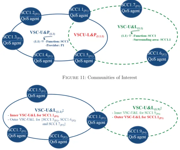
Figure11: Communities of Interest
Figure 12: Cross-organizational distributed Management
4.3.3 Management based on Communities of Interest
The virtual communities that we offer are also called communities of interest because they ga-ther services sharing a common interest (Figure 11). We have designed two types of communities of interest : the first type is called VSC-U&P (Ubiquity and Provider based Virtual Service Com-munity). As shown in Figure 11, VSC-U&P (1.1) gathers all SCC1 ubiquitous services belonging to different platforms from the same provider P1.
The second type of community is called VSC-U&L (Ubiquity and Location based Virtual Service Community) and gathers ubiquitous services belonging to the same provider. It is associated with a service and gathers services that are ubiquitous to it and belonging to its geographic surroundings area. In Figure 11, VSC-U&L is associated with the service SCC1.1 and contains services ubiquitous to SCC1.1 and belonging to its surrounding area. As we see, the VSC-U&L is trans-organizational and contains multivendor services. The intersection of these two types of communities of interest is another type of community denoted VSCU-L&P, containing ubiquitous services in the same geographical area and belonging to the same supplier.
4.3.4 Cross-organizational distributed Management
Having described these different types of communities, the question that arises is who will create and maintain the cross-organizational VSC-U&Ls ? To answer this question, we consider that each platform assigns to each of its deployed services a VSC-U&L community. The platform either creates a new VSCU&L or it attaches it to an existing VSC-U&L. In both cases, the community becomes Inner VSC-U&L for this service. All other services that will be selected by this community will see it as Outer VSC-U&L :
Figure 13: Virtual Communities and SCC
– Outer VSC-U&L for other selected services.
Thus, only the platform SCC1.1, source of this community, will be responsible for its maintenance. For example, in the following figure (Figure 12), the deployment of SCC1.1 service caused the creation of the VSC-U&L (1.1) community. Thus, it is Inner for SCC1.1 and will be Outer for the other services.
If we consider the deployment of another service SCC1.9 by another supplier, a new VSC-U&L (1.9) community is created. This new community is Inner for the service SCC1.9 and Outer for the other services it chooses, including the SCC1.1 service. Therefore, the platform that contains the SCC1.1 service is responsible for the maintenance of VSCU&L (1.1). The platform containing the SCC1.9 service will be responsible for the maintenance of the VSC-U&L (1.9) community. Each platform maintains the VSC-U&Ls that it has created.
4.3.5 Management of Virtual Communities
To summarize : at the architectural level each service is associated with a single VSC-U&P and only one Inner VSC-U&L. It may participate in several Outer VSC-U&Ls, and may be pre-provisioned in several VPSNs (Figure 13). However, the questions that arise is how to create VSCUs at the functional level, how to attach new deployed services to existing VSCUs, and how to maintain these VSCUs ?
In addition to the tables presented in Figure 8, we have :
– The VSCU Attachment allows to attach an already deployed service to an existing VSC-U&P and/or Inner VSC-U&L.
– The VSCU Creation allows to create a VSC-U&L for a deployed service that has not yet been attached. This community will be considered as his Inner VSC-U&L.
For the VSCUs maintenance we offer two distinct services : the Internal VSCU Maintenance which belongs to the same platform as the degraded service and that manages the associated Inner VSC-U&L and VSC-U&P to this degraded service ; and the External VSCU Maintenance that manages the Outer VSC-U&L to which belongs the degraded service and thus belongs to the service platform responsible for this community. To highlight the event driven and distributed approach we
Figure 14: Virtual Communities : Management
provide for the maintenance of virtual communities, we present an organizational implementation of external maintenance.
In summary :
– VSCU Creation creates a VSC-U&L for a deployed service ; this community will be consi-dered as his Inner VSC-U&L.
– VSCU Attachment attaches a deployed service to existing communities.
– Internal VSCU Maintenance maintains the Inner VSC-U&L and VSC-U&P associated to the degraded service. Belongs to the same platform as the degraded service
– External VSCU Maintenance maintains the Outer VSC-U&L to which belongs the de-graded service. Belongs to the platform of the service responsible for this community.
Take the case of a service SCC3.2 (Figure 14) provided by provider P2. SCC3.2 is part of two communities : VSC-U&L(3.4) under the responsibility of the SCC3.4 service ; and VSC-U&L(3.1) under the responsibility of the SCC3.1 service. These two communities are thus considered as Outer VSC-U&L for SCC3.2, so it is not its platform that handles of their maintenance. Suppose now that the SCC3.2 Service is deteriorating. We believe that a maintenance of a community requires three successive degradation detections in order to be sure that the service is no longer available. Thus, for each degradation the QoS agent sends OUTcontracts to all the services responsible of its Outer VSC-U&L. Namely, it sends OUTcontracts to SCC3.1 and SCC3.4, which in turn sends a notification to their respective Events Manager.
However, the Events Manager only sends a notification to the External VSCU Maintenance service if it receives the three successive OUTContract from the same service. Assume that this is the case for the SCC3.2 service. The Events Manager of the P1(1) (resp. P1(2)) platform is managing the VSC-U&L(3.1) (resp. VSC-U&L(3.4)) community, so its is his role to notify its External VSCU Maintenance.
For this, we detail the case of the External VSCU Maintenance of platform P1(1) (the mechanism is the same for P1(2)). This service sends a request to its Infoware to remove the SCC3.2 service from the community. The Infoware in turn notifies the Infoware of the SCC3.2 platform. Thus the
VSC-U&L(3.1) community is no longer Outer for SCC3.2. To replace this degraded service, the External VSCU Maintenance discovers another service SCC3.6 that is ubiquitous to SCC3.1 and which is in its surrounding area. So it adds it to the community and notifies the Infoware which in turn notifies the Infoware of the platform of SCC3.6. Thus we get a new VSC-U&L(3.1) with SCC3.6 instead of SCC3.2.
In parallel to this external maintenance, a maintenance also occurs internally, maintaining the Inner VSC-U&L and the VSC-U&P associated to SCC3.2. To do so, the SCC3.2 service sends Out-Contracts internally towards its Events Manager which after the 3rd successive out contract notifies the Internal VSCU Maintenance which performs the maintenance.
4.4 Tactical decision
At the top of the composition, the management decisions are taken by the MAPE loop. These decisions are not at the operational level and as they depend on available resources, they rather are at tactical level.
Indeed, Cloud computing technology now allows customers to use cloud services according to a pay-as-you-go style. Answering a user request, together with its associated QoS, the cloud provider infrastructure proceeds to the corresponding allocation of non-shareable components adding or reducing the number of components in the service session (VPSN) according to the required capacity. These decisions are in general depending on the business rules which are defined in the knowledge base ; this is why, we consider them at tactical level.
This may be implemented using a software architecture with a multiple level autonomic manage-ment, in which the MAPE loops of all service compositions will interact with some shared controllers managed by the service providers. The VPSN management is obtained by the combination of the local actions of the MAPE loop components, with the external resource Managements. When some corrective action is required within a self-controlled application, the Analysis component of its MAPE loop receives the notification (OutContract) from some QoSControl components, and sends the diagnostic to the Planning component. This one will request either a replacement SCC com-ponent, or some additional resources, to the external management environment (through the VPSN-management interface). When receiving back the requested resources, it will build a reconfiguration script, and pass it to Execute. In Section 7, we will show an example of such an addition.
4.5 Strategic decision
Beyond these actions that can be automated, we have all the other actions of the FCAPS (Fault, Configuration, Accounting, Performance, Security) model that handle the overall management, for example, the configuration and activation actions of the QoS components, which generally are initia-lized by the architect according to SLA. FCAPS are standards of Telecommunications Management Network and framework for network management [30]. Finally, the rules that govern the whole are called high level and are of strategic nature. Figure 15 shows the complementarity of automated management actions : operational, tactical, and strategic. Operational decision corresponds to dy-namic reaction VSC. Tactical decision is realised in the MAPE loop based on application of usage and context. Strategic decision corresponds to high level management decisions.
5
Application design with autonomic control
In this section we discuss the different possibilities that our methodology offers to the application designer, when assembling components from (Cloud) services to build an autonomic application obeying SLA constraints. This means chosing which components should be SCC or not, how to organize and compose SCCs in the hierarchy, where to place the autonomic intelligence, and how to relate the monitored and controlled components with the autonomic management.
Figure 15: Composition Management
5.1 Composing SCC components
In Section 3, we have defined a GCM architecture for a standard SCC component, in which monitors observe activity on the server and client interfaces of the component. The SCC structure has many advantages for building flexible cloud service-based applications, in which services are stateless, thus easily mutualizable, replicable and exchangeable.
Most of the elements in an application will be SCC components, composed hierarchicaly using the usual GCM structure. Not all components in the hierarchy need to be monitored and controlled ; both primitive components (encapsulating one single primitive service) and composite components can be controlled, and imbricated components can also be controlled simultaneously at several level of the hierarchy. In case of QoS violation, the control loop of the application will decide at which level(s) the problem should be corrected. It is the responsability of the application designer to decide which components should be controlled, and designed using the SCC template.
5.2 Using non-SCC components
There are cases where a component cannot use the basic SCC definition from Section 3. This is the case typically when this component is waiting for the result of some remote computation, before being able to finish its own task. For this kind of service, the structure of the basic SCC is not suitable : the monitoring of the service must be done between the arrival of the client re-quest on the server interface, and the return of the result to the client, back through the same interface, when the computation is achieved. For these cases, we have a specific template with a single InOutMonitor inserted at the server interface, and a QoSControl component slightly dif-ferent, taking all its information on one single client non-functional (NF) interface bound to the InOutMonitor, and controlling the requested QoS. An example is shown in Figure 16.
Remark that such services with returned values should also be mutualisable, so they have to memorise the ids of the client requests, and use them later to return the result at the corresponding address. So they are stateful in some sense, and specific care will have to be taken if they need to be replaced. As a consequence, to build applications as much "as a service" as possible, meaning stateless, mutualisable and ubiquitous, the architect should be careful to separate the return value management part as much as possible, and to stick to the basic SCC model for all other components. Last, we have to decide where the intelligence of the autonomic control will be. In principle, there is no problem having autonomic control distributed at several places and at several levels in an application : this may even be more efficient, for very large and distributed systems. However, in many cases, it will be sufficient to have one single component, at the toplevel of the application, gathering all of the QoS information, and providing the autonomic management. This mechanism is detailed in the following section.
5.3 Global autonomic control : the MAPE loop
One of the most common ways to provide autonomic behaviour is to rely on a feedback control loop that follows four canonical activities : collect, analyse, decide, and act. This loop defines four phases : Monitor, Analyse, Plan, and Execute and it is usually referred to as the MAPE autonomic control loop. In GCM, we propose a component architecture that can be embedded in the component membrane and ease the programming of autonomic adaptation procedures. These MAPE loops can either act at the top level of the composition, but also interact through the hierarchical nature of GCM applications.
We will see in the next section that SCCs are composed into compound services at a certain level, called the VPSN. It is at this level that the autonomic adaptation will be performed through the use of QoS management components in the membrane ; it is at this level that the SLA will be defined and guaranteed. However, interaction with lower-level services part of the composition is still necessary, at least to monitor the services and determine the service that should be changed in order to guarantee the agreed quality of service. For this reason each service encapsulated into a component is equipped with monitoring interfaces and reports its status to the compound service. The intelligence of the adaptation is placed in the analyser of the compound service, that, based
Figure 17: SLA generic model
on global monitoring of its performance, on monitoring information of the sub-services, and on global additional requirements, will decide the instances of the sub-services that must be part of the composition, possibly changing the set of involved sub-services to adapt to execution settings and to contract requirements.
6
From SCC component to SLA
This section complements our contributions to the non-functional aspects through a QoS mo-del. It presents the generic SLA (Service Level Agreement) model that we have proposed in the OpenCloudware project and as an ETSI draft [11]. The specificity of this model is the following : it explicits on the one hand the SLO user requirements, and on the other hand the provider of-fers (service and QoS) associated to the same QoS model (four generic criteria). To meet the SLO requested by the user, the provider offer will rely the composition of several SCC components.
First, in this section, we begin with the description of our SLA approach (Section 6.1). Next, we present (Section 6.2) the SLO expression in adequacy with the management actions provided by SCC components. Finally, in Section 6.3, its SLA generic model.
6.1 Approach
Our approach is to propose a SLA model that explicits and aligns user requirements (SLO and Obligation) and provider offers (services) through the model and the QoS expression [4]. As we have seen in Section 3, a service (SCC component) is defined by its function and its behaviour, described according to four QoS criteria with information on QoSCriteriaName (Availability, Integrity, Time, Capacity) and QoSCriteriaValue (design, threshold and current value). The user will express his/her SLO through the four criteria. The provider selects in his/her catalog the SCC component to best meet the SLO request.
The personalised service delivery is performed according to QoS of VPSN user session. The VPSN guarantee is taken into account in SLA. For each VPSN we introduces a set of services necessary to control and manage the end-to-end QoS. Thanks to the MAPE loop of the SCC components, the
service level management is automatised. The service delivery takes into account the user profile, the context, and SLO expressed by the user.
6.2 Service Level Objective
The Service Level Objective (Figure 17, bullet 3.1) is the means for the user to express his needs. The objectives expressed by the user may be linked to the end-to-end QoS. The end-to-end (E2E) objectives define the final service QoS level (compound service) provided to the user. Indeed, if the customer requires a service composition, he may then precise the conditions linked to their operation such as response time, availability rate and scalability.
For Springoo example, the user requires that the processing time of his service is less than 2s in 90% of the cases, if the number of requests processed is less than 1000 req/s. On the other hand, if the number of requests is between 1000 req/s and 2000 req/s, he may still require a processing time less than 2s but with a rate of failure less stringent (for example 80% instead of 90% of the cases).
The SLO linked to this user needs are then the followings :
– SLO1 : E2E processing time < 2s if the request number is <1000 req/s in 90% of the cases. – SLO2 : E2E processing time < 2s if the request number is >1000 and <2000 req/s in 80% of
the cases.
6.3 Service Level Agreement
The SLA is a document, a contract, that defines the specific and personalised deal, accord required between a service provider and a client [29]. After having introduced the SLA content, the Figure 17 formalises the SLA template generic model based on UML. The SLA template generic model is composed by :
1. Parties (Signatory Party and Third Parties). 2. High level constraints
3. User part, corresponding to the demand : Service Level Objective and coverage.
4. Provider part, corresponding to the offer : Services offered as well as the associated QoS. 5. The SLA contract conditions.
To clarify our SLA generic model, we take the use case Springoo presented in Chapter 7. The Parties represent the contracting entities of a SLA contract (fig Figure 17, bullet 1). We classify these entities as “Signatory parties” and “Third Parties”. The first set represents the contrac-tual parties that can include the provider, the end-user, the developer (Springoo resource requester), etc. The second set represents the trusted third parties involved in the SLA contract including the network provider, the monitoring provider, etc. Not applicable to the Springoo.
The proposed SLA model includes the conditions imposed by the provider and/or the consumer high level constraints (Figure 17, bullet 2). We propose the following classification of constraints : strategic, financial, juridical, and technical. Strategic constraints represent either the strategies requested by the user or those applied by the provider. Financial constraints are the conditions related to the payment and usage patterns. Juridical constraints define legal constraints such as licensing rules, editing rights, etc. Technical constraints represent the requirements determined by the provider to execute the requested service. For example, the provider may require the user to have a specific browser for Springoo.
The user part (Figure 17, bullet 3) should be composed of SLO, geographical features and coverage.
The offer of the provider represents the catalog of components available on the PaaS. The providers offer SCC components that are differentiated by their QoS levels, their prices and how they are built, deployed and managed. In a specific SLA (Figure 17, bullet 4) we find the result of the choice of SCC components corresponding to the SLO of the user and constitute its VPSN (SCC composition). In our Springoo example, the selected SCCs are an Apache-SCC and a Jonas-SCC component whose composition meets the requested SLO (number of requests per second, response time and integrity 6.2). The classes (Figure 17, bullet 5) represent the terms of contracts. We