HAL Id: hal-00966156
https://hal-mines-paristech.archives-ouvertes.fr/hal-00966156
Submitted on 26 Mar 2014HAL is a multi-disciplinary open access archive for the deposit and dissemination of sci-entific research documents, whether they are pub-lished or not. The documents may come from
L’archive ouverte pluridisciplinaire HAL, est destinée au dépôt et à la diffusion de documents scientifiques de niveau recherche, publiés ou non, émanant des établissements d’enseignement et de
Fracture of Zircaloy-4 cladding tubes with or without
hydride blisters in uniaxial to plane strain conditions
with standard and optimized expansion due to
compression tests
Arthur Hellouin de Menibus, Quentin Auzoux, Philippe Mongabure, Vincent
Macdonald, Thomas Le Jolu, Jacques Besson, Jérôme Crépin
To cite this version:
Arthur Hellouin de Menibus, Quentin Auzoux, Philippe Mongabure, Vincent Macdonald, Thomas Le Jolu, et al.. Fracture of Zircaloy-4 cladding tubes with or without hydride blisters in uniaxial to plane strain conditions with standard and optimized expansion due to compression tests. Materials Science and Engineering: A, Elsevier, 2014, 604, pp.57-66. �10.1016/j.msea.2014.02.075�. �hal-00966156�
Fracture of Zircaloy-4 Cladding Tubes with or
without Hydride Blisters in Uniaxial to Plane
Strain Conditions with Standard and
Optimized Expansion Due to Compression
Tests
Arthur Hellouin de Menibus
∗1,3, Quentin Auzoux
2, Philippe
Mongabure
4, Vincent Macdonald
2,3, Thomas Le Jolu
2, Jacques
Besson
3, and Jerome Crepin
31CEA Saclay/DEN/DANS/DMN/SRMA, 91191 Gif-sur-Yvette, France
2
CEA Saclay/DEN/DANS/DMN/SEMI, 91191 Gif-sur-Yvette, France
3
Mines ParisTech/Centre des materiaux CNRS UMR 7633, 91003 Evry, France
4
CEA Saclay DEN/DANS/DM2S/SEMT, 91191 Gif-sur-Yvette, France
Published in 2014 in Materials Science and Engineering:
http://www.sciencedirect.com/science/article/pii/S0921509314002287
Abstract
Two optimizations of the Expansion Due to Compression (EDC) test, which induces a near uniaxial loading, were proposed and de-veloped to reach higher biaxiality ratios (ratio between mechanical quantities in axial and in circumferential direction). The first opti-mization, named HB-EDC for High-Biaxiality EDC, allowed to reach transverse plane strain conditions. The second optimization, named VHB-EDC for Very High Biaxiality EDC, was designed to reach higher loading biaxiality ratios. These optimized EDC tests were performed
at 25◦C, 350◦C and 480◦C on unirradiated hydrided Cold Worked
Stress Relieved (CWSR) Zircaloy-4 samples. First, samples unhy-drided or uniformly hyunhy-drided up to 1130 wppm were tested. Secondly, samples hydrided at 310 wppm with a hydride blister were tested. A large ductility reduction is induced by the increase in biaxiality level in absence of a hydride blister or with small blisters (<50 µm deep). The fracture strain decreases quickly with the blister depth at 25◦C, but
more progressively at higher temperature. An equation that quantifies the fracture strain reduction with the blister depth is proposed. Even-tually, one of the tests developed in the present study, the HB-EDC test, was proven to be a good compromise between the test complexity and the stress state reached. It is a good candidate to characterize the mechanical behaviour of irradiated cladding.
Keywords: Zircaloy-4, Zirconium, Expansion Due to Compression, Hy-dride Blister
1
Introduction
The most critical postulated reactivity Initiated Accident (RIA) scenario in a nuclear pressurized water reactor is a control rod ejection that induces a large energy deposition in the surrounding fuel pellets (NEA [1]). As a consequence, the pellets from the surrounding fuel rods expand suddenly, which induces deformation of the cladding tubes in the first phase referred to as PCMI for Pellet Cladding Mechanical Interaction. The evolution of the thermomechanical loading applied on the cladding tube during the PCMI phase of a fast RIA transient (CABRI REP-Na5 test on a uranium - Zircaloy-4 fuel rod) was recently published by Hellouin de Menibus et al. [2]. It was shown the stress biaxiality (axial to circumferential) is included between 0.6 and 0.95.
The detrimental effect of a high biaxiality level mechanical loading on the ductile fracture is well known (Rice and Tracey [3]). Concerning zirconium al-loys, this effect was confirmed on unirradiated recrystallized Zircaloy-2 sheets (Yunchang and Koss [4]), on unirradiated recrystallized Zircaloy-2 tubes by Maki and Ooyama [5], on unirradiated recrystallized Zircaloy-4 by Andersson and Wilson [6] and on unirradiated and irradiated Zr-1%Nb tubes by Kaplar et al. [7].
In order to assess the behavior and the fracture of unirradiated and ir-radiated cladding tube in RIA representative conditions, the PROMETRA experimental program is being pursued at the CEA in collaboration with EDF and IRSN (Cazalis et al. [8]). The PROMETRA database includes tests at different biaxiality levels from uniaxial to plane-strain, with uniax-ial tests in cladding axuniax-ial direction, uniaxuniax-ial ring tests, plane strain tensile tests and burst tests. Nevertheless, and as recently stated by Desquines et al. [9], additional work is required to predict the cladding tube fracture at RIA representative stress state. In addition, it is important to improve the understanding of the effect of the hydride microstructure on the cladding fracture.
During the PCMI phase, the mechanical loading on the cladding tube is induced by the thermal expansion of the fuel pellet plus a possible lim-ited contribution of the intra-granular fission gas induced swelling for high enthalpy RIA transients (higher than 110 cal/g in CABRI tests according to Papin et al. [10]). Therefore, displacement-controlled mechanical tests should be preferred to characterize the cladding fracture in the PCMI phase. Punch tests techniques [11, 12] are suitable to provide information for various stress state conditions. However, these tests can only be performed on sheets, which are generally not fully representative of tubular sample in terms of me-chanical behaviour and fracture. For instance, Raynaud et al. [13] found that the fracture toughness is lower in CWSR Zircaloy-4 sheets than in tubes. To the authors knowledge, three mechanical tests allow to test tubular samples with a high biaxiality mechanical displacement-controlled loading. The ring Plane Strain Tensile test (PST) [14] and the Ring Compression Test (RCT) [15] allow to reach transverse plane-strain conditions in the gauge section. The last one is the magneto-forming test (Leclercq et al. [16]), where even higher biaxiality ratios can be reached. The main drawback of these tests is that the induced mechanical fields in the cladding tube are highly heteroge-neous. Thus, the fracture strains level obtained with these tests are hardly comparable between each other and are highly dependent on the technique used to measuring it (this would be illustrated for PST tests in the present article). As a consequence, there is a need for new mechanical tests that induce RIA representative loading biaxiality with homogenous mechanical fields to define reliable cladding tube fracture criteria for the RIA PCMI phase.
The Expansion Due to Compression test developed by Grigoriev et al. [17, 18] consists in stretching the cladding in the circumferential direction
by using the compression of a pellet placed inside the tube by means of two pistons. It induces a homogenous circumferential plastic strain field in the sample circumference : finite element calculations showed the fracture circumferential plastic strain in a test at 25◦C is only 15% higher on the
inner diameter than on the outer one (Le Saux et al. [19]). Nevertheless, the sample’s ends are free to move axially so that the loading biaxiality is close to the one of an uniaxial tensile test in the circumferential direction. A similar mechanical test referred to as Expanding Plug Wedge Test was proposed by Hendrich et al. [20, 21, 22], where the lower piston is replaced by a fixed platform.
The present article reports the development of two new mechanical tests based on the EDC test with two pistons, named High Biaxiality - Expansion Due to Compression (HB-EDC) and Very HB-EDC (VHB-EDC). Both are based on an optimization of the EDC tests that consists in adding an axial contribution in the mechanical loading, a concept first proposed by Le Saux et al. [19]. These optimized EDC tests ability to quantitatively character-ized the cladding tube fracture was then assessed on unirradiated Zircaloy-4 samples, with hydrogen content from 0 to 1130 wppm, and afterward on 310 wppm hydrided samples containing a hydride blister. Hydride blisters are local high hydrogen areas that could grow on Zircaloy-4 cladding exter-nal surface by a thermodiffusion mechanism. They induced a reduction in the cladding tube fracture resistance, in particular in the RIA PCMI phase (Fuketa et al. [23]).
First, the HB-EDC and VHB-EDC setups are presented. Then, the exper-imental fracture strain at 25◦C and 350◦C of unhydrided and homogeneously
hydrided samples, without hydride blisters, obtained with EDC, HB-EDC and VHB-EDC tests are compared. The results of such mechanical tests at 25◦C, 350◦C and 480◦C on samples with hydride blisters are presented
subsequently. Then, the fracture strain reduction in function of blister depth observed in the present study is compared to previously published results. Eventually, the advantages and drawbacks of the optimized EDC tests are discussed.
2
Material
2.1
Non hydrided samples
The samples were tubes of cold worked stress-relieved unirradiated Zircaloy-4 provided by CEZUS R. They measured 9.5 mm outer diameter and 0.57 mm in thickness. Their weight composition is 1.2 to 1.7% Sn, 0.18 to 0.24% Fe, 0.07 to 0.13% Cr, 0.1 to 0.14% O, Zr balance, according to the ASTM B 350.90 specification. The zirconium grain size was measured on 150x mag-nification polarized pictures taken with an optical microscope on polished radial-circumferential and radial-axial cross sections. The grain size was 2.5±0.7 µm in the radial direction, 3.7±0.7 µm in the circumferential one and of about 10 µm in the tube axial direction. The material texture was not characterized experimentally on the material batch used in this study. However, this material was obtained with the standard industrial manufac-turing route for CWSR Zircaloy-4. It induces that most of the zirconium < c > axis are oriented at ±30◦ with respect to the tube radial direction
and the < 10¯10 > direction is aligned with the tube axial direction (Murty and Charit [24]).
2.2
Hydrided samples
Specimens were hydrided by gaseous charging at 400◦C. Hydrogen contents
were quantified by hot vaccum extraction, the following concentrations were obtained: 310±80 wppm, 840±120 wppm and 1130±150 wppm. The short gaseous charging duration at 400◦C (<15h) is not expected to induce either
significant dislocations recovery or material recrystallization (Dunlop et al. [25]).
2.3
Samples with hydride blisters
Hydride blisters of various depth were formed on 310 wppm homogeneously hydrided samples by thermodiffusion following the experimental procedure proposed by Hellouin de Menibus et al. [26]. The limited process temperature (375◦C) and short duration (<24h) prevent the material from significant
dislocations recovery. The blister depth is defined by the distance between the blister induced protrusion (not the blister external diameter) and the interface matrix-blister, as defined in [26].
3
Procedures
3.1
Testing Machine and test monitoring
An Instron R electro-mechanical tensile testing machine equipped with a 50 kN load cell was used. Above 1 kN, the uncertainty on the load measure-ment was certified lower than 0.25%. For a requested 1.5 mm/s cross-head displacement rate, the effective rate was 1.528 mm/s±2.5% on average on 40 samples. The samples were heated with a resistive furnace placed around the tensile line. The temperature uncertainty was 5◦C at 350◦C and 10◦C
at 480◦C. The tests were performed after an 1 h heating so no dislocations
recovery is expected. Dunlop et al. [25] showed that the dislocation recovery of CWSR Zircaloy-4 starts to affect significantly the material hardness after a duration t that follows the analytical expression t = 2.97 × 10¹⁰
e−0.0498T
with T the temperature in ◦C and t in hours, in the 400◦C to 520◦C
tem-perature range (approximately 1h15 at 480◦C). The tests were recorded by a
high speed optical camera at frame rates equal to 500Hz or 1000Hz to detect accurately the sample fracture. The total (elastic plus plastic) circumfer-ential strain at fracture was measured with the external diameter variation between the last frame before fracture and the first frame of the test. The spatial resolution of the camera was 45µm/px. It leads to a 0.01 uncertainty in the circumferential strain measurement. The elastic contribution to the circumferential strain at fracture was not subtracted. Nevertheless, the max-imum stress at 25◦C in uniaxial ring test is lower than 900MPa [27] and the
elasticity modulus is about 97GPa at this temperature [28], which leads to limited elastic strains, lower than 0.01.
3.2
Expansion Due to Compression (EDC) tests
The EDC test design and the inversor device used to induce a compressive loading from a tensile testing machine are illustrated in Figure 1(a). Pellets are made of PTFE (Polytetrafluoroethylene) for tests at 25◦C and 99,999%
pure aluminum for tests at 350◦C and 480◦C. The pellet materials are the
same as the ones used in EDC tests by Le Saux et al. [19]. In all tests, Teflon pellets were 8.10 mm in diameter and aluminum pellets were 8.20 mm in diameter. Teflon and aluminium pellets diameter are not equal to ensure that the cladding tube is not loaded by the thermal expansion of the pellet. The mechanical behaviour of the pellet tested alone in compression
is showed in Figure 2. The EDC samples are 30 mm long and the pellet are 25mm long. EDC tests with such long specimens first induce circumferential strain localization in two folds that progressively move toward specimen mid-plane and then join together (folds are visible in Figure 3(a)). The folds are more important and remain up to a higher axial piston displacement when the test temperature is higher. A solution to avoid these folds is to reduce the specimen length. No folds were observed at 350◦C in additional short
length EDC tests with 20 mm long tube and 15 mm pellet at 350◦C (not
further detailed in the present paper). It was chosen to keep on using 30 mm samples to reach high circumferential strain, and because the HB-EDC and VHB-EDC samples that are described hereafter are also 30 mm long.
The EDC specimen circumferential strain rate for a 1.5 mm/s piston axial displacement rate was determined by measuring the external diameter varia-tion with an edge detecvaria-tion post-processing, and subsequent synchronizavaria-tion with the load-piston axial displacement evolution. Two circumferential strain rate regimes are observed at 25◦C, 350◦C and 480◦C (figure 3(b), 3(c) and
3(d)). The slope change corresponds to the folds merging. The diameter vari-ation plotted in all these figures is the maximum diameter. It corresponds to the folds if some are present. After the folds merging, the circumferential strain rate remains almost constant with the diameter variation. For a given cross-head displacement rate, the circumferential strain rate is higher when the test temperature is higher. However, the circumferential strain rate re-mains in the range 0.05-0.1/s for a 1.5 mm/s piston axial displacement rate. No local temperature increase due to plastic dissipation is expected in this strain rate range (Hellouin de Menibus et al. [29]).
3.3
High Biaxiality - Expansion Due to Compression
(HB-EDC) tests
The HB-EDC (figure 1(b)) is an optimization of the EDC test (figure 1(a)) that allowed to reach plane strain conditions (Le Saux et al. [19]). Screwed ends are welded to the sample ends. The screwed ends are themselves screwed in the ”Axial transfer” part placed on the ”deck” (the nomenclature is defined in Figure 1(b)) . The two ”columns” maintain the distance between the two ”decks” constant to prevent the tube from axial contraction. The columns are in recrystallized Zircaloy-4 and the other parts in Ti-6Al-4V alloy. The thermal expansion of Titanium alloys (5.6 to 9.5 × 10⁻⁶/K [30]) is similar to
the Zircaloy-4 one (4.95 to 12.6 × 10⁻⁶/K [31]). Some folds are also formed
in HB-EDC tests at high temperatures, but they are more limited than in EDC tests due to the presence of axial stress that limits the circumferential strain localization.
3.4
Very High Biaxiality - Expansion Due to
Compres-sion (VHB-EDC) tests
In order to reach higher biaxiality levels, two circumferential retainers sepa-rated by a given distance L are placed around the tube in HB-EDC config-uration (figure 1(c)). This testing configconfig-uration have been suggested by Le Saux et al. [19], who showed that the biaxiality level is increased when the distance L decreases. A VHB-EDC test with L=10 mm distance between the two circumferential retainers would be referred to as ”VHB-EDC L=10”. VHB-EDC L=10 and VHB-EDC L=6 tests were performed in the present study. Le Saux et al. [19] performed finite element calculations for EDC, HB-EDC and VHB-EDC with L = 8 - 6 - 4. Based on VHB-EDC L=8 cal-culations, it is expected VHB-EDC L=10 would induce similar stress state than HB-EDC, that is the distance L = 10 is too large to induce a stress biaxiality increase. Thus, the aim of the VHB-EDC L=10 tests performed in the present study was to validate the VHB-EDC concept, and the resulting fracture strain can be compared with the one obtained with HB-EDC tests. Le Saux et al. [19] showed the VHB-EDC L=6 setup would induce a higher biaxiality level for a given strain level than the HB-EDC one, typically plus 0.2 in the σzz/σθθ ratio. HB-EDC and VHB-EDC samples were 30 mm and
pellets 20 mm in height (while in EDC tests the samples measured 30 mm and pellets 25 mm in height).
4
Results
Some VHB-EDC L=6 samples failed at the corner of the circumferential retainer. This issue is discussed in the discussion section. Only EDC, HB-EDC and VHB-HB-EDC L=10 would be discussed in the present section. The fracture strain measured in the tests performed are listed in Table 1 and displayed in Figure 4.
4.1
Homogenous sample
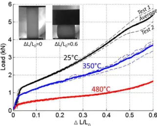
At 25◦C, the circumferential fracture strain of unhydrided samples was 0.64
on average in EDC tests (Figre 5). It was reduced to 0.21 (-67%) on average for HB-EDC or VHB-EDC L=10 tests (figure 5) due to the increase in loading biaxiality. The fracture strain decreases with the hydrogen content for all tests : EDC, HB-EDC and VHB-EDC L=10. However, the fracture strain reduction due to the higher loading biaxiality between EDC and HB-EDC or VHB-EDC L=10 tests is similar regardless the hydrogen content within the explored range : It was -67% on unhydrided specimens, -67% at 310 wppm and -69% at 840 wppm. The fracture strain reduction from uniaxial to plane strain conditions was not measured for 1130 wppm samples because the scatter in the fracture strain was not negligible anymore compare to its magnitude (0.05 to 0.1). The post mortem aspect of a 300 wppm hydrided EDC sample (0.64 fracture strain) and a HB-EDC sample (0.21 fracture strain) tested at 25◦C are showed in Figure 6(a).
At 350◦C, the EDC samples without blister did not fail (figure 6(b) on
the left side). On the other hand, HB-EDC and VHB-EDC L=10 samples failed at fracture strains ranging from 0.26 on average for 0 wppm samples to 0.21 for 1130 wppm samples.
At both temperatures, 25◦C and 350◦C, the fact that HB-EDC and
VHB-EDC L=10 results in similar fracture strains confirmed the loading biaxiality induced in these tests is similar (see section 3.4).
4.2
Samples with hydride blisters
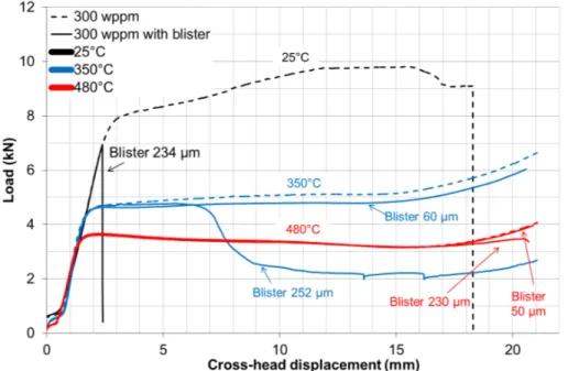
The evolution of the load with the cross-head displacement applied to samples with or without blister are reproducible prior to specimen fracture in EDC tests (figure 7) and in HB-EDC tests (figure 8) at 25◦C, 350◦C and 480◦C.
At 25◦C, the fracture in EDC and HB-EDC is sudden : it takes place
between two optical frames taken at 500 Hz in HB-EDC tests (Figure 9(a)). The drastic reduction of the cladding ductility at 25◦C in presence of a
blister is visible on the samples post mortem aspect showed in Figure 6(a). The quantitative fracture strain reduction with the blister depth is showed in Figure 10.
At 350◦C and 480◦C, the load-displacement evolution (figure 7 and 8)
shows that the fracture in presence of a blister is not sudden anymore. This is clearly visible with the fracture process of an HB-EDC test with a blister
tested at 480◦C (figure 9(b)). At 350◦C, the EDC and HB-EDC samples
are still sensitive to the presence of a blister (figure 7 and 8). Figure 6(b) evidences that EDC sample can only failed at 350◦C when embrittled by a
blister. At 480◦C, the presence of a blister also reduces cladding ductility
(figure 10), but cladding tubes can sustain large deformation levels prior to fracture (0.10 - 0.15) (figure 7 and 8).
Contrarily to the case of homogeneously hydrided samples without blister (section 4.1), no significant biaxiality effect is found on the fracture strain of samples with 150 µm to 255 µm deep blisters : similar fracture strains are obtained with EDC and HB-EDC tests (figure 10). One EDC tests at 350◦C and one at 480◦C with 50-60 µm deep blister did not fail. This
suggests that a blister depth threshold exists above which the fracture strain does not depend on the macroscopic loading biaxiality. Contrarily to the case of homogeneously hydrided samples without blister (section 4.1), no significant biaxiality effect is found on the fracture strain of samples with 150 µm to 255 µm deep blisters : similar fracture strains are obtained with EDC and HB-EDC tests (figure 10). One EDC tests at 350◦C and one at
480◦C with 50-60 µm deep blister did not fail. This suggests that a blister
depth threshold exists above which the fracture strain does not depend on the macroscopic loading biaxiality.
The fracture surfaces observed by Scanning Electron Microscope (SEM) of EDC, HB-EDC and VHB-EDC L=10 samples with blister are similar. At 25◦C, the fractured cross section is perpendicular to the circumferential
di-rection but the aspect of the blister and of the zirconium bulk are different (figure 11(a)). The blister fracture surface is clearly brittle. On the other hand, the bulk fracture surface consists in several steps corresponding to the hydrides with small dimples in between. This macroscopically ”flat” frac-ture of the bulk beneath the blister is not representative of the one observed during RIA, where the bulk fracture is slanted in the thickness (Papin et al. [10]). At higher temperature, the blister fracture is also brittle (figure 11(b)), even at temperature levels as high as 600◦C (tests results are not
detailed in the present paper). A zone with large dimples is observed right beneath the blister. Then, the remaining ligament has small elongated dim-ples and the surface is slanted in the thickness (figure 11). Thus the fracture scenario at high temperature is 1) blister fracture (or opening considering it is often cracked before testing - refer to Hellouin de Menibus et al. [26]), 2) Crack blunting and propagation in the bulk and 3) slanted fracture of the remaining ligament by plastic instability. The extension of the crack in the
radial direction is slightly longer than the blister depth as it also includes the zone with large dimples. This is in agreement with the fracture surface observations performed on CABRI REP-Na8 (Papin et al. [10]). Therefore, the fracture process in EDC, HB-EDC and VHB-EDC at 350◦C and 480◦C
is representative of the one observed after integral tests on rods with a blister (Papin et al. [10]).
5
Discussion
5.1
Effect of the load biaxiality level on the fracture
strain
First, regarding homogenous sample, without any hydride blister. Yunchang and Koss [4] found that the fracture strain decreases by 68.6±2.6% on average when the loading biaxiality increases from σzz/σθθ = 0 to σzz/σθθ = 0.5 on
recrystallized Zircaloy-2 sheets, regardless of the hydrogen content from 21 to 615 wppm. This is in good agreement with the average ratio equal to 67.7±1.4% found in the present study. This further confirms that HB-EDC tests induce near transverse plane-strain conditions.
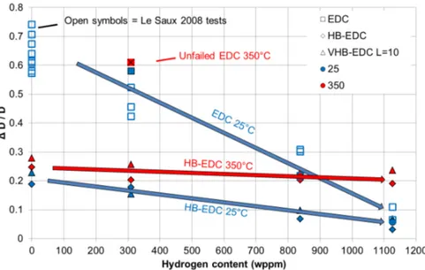
Secondly, regarding samples with an hydride blister. Previous studies showed that similar fracture strains were obtained on Zircaloy-4 sheets con-taining a blister regardless of the loading biaxiality level between plane-strain (Pierron et al. [32]) and equibiaxial (Glendening et al. [12] - figure 12). Nev-ertheless, the unfailed EDC tests with 50-60 µm deep blister suggest that a blister depth threshold might exist below which the macroscopic loading biaxiality does impact the fracture strain. The existence of such a threshold should be further confirmed by additional tests. For large blisters, the far field biaxiality does not need to be taken into account in a fracture criterion, which could thus be defined with either standard EDC tests or optimized EDC tests.
The fracture strain in plane-strain measured by Pierron et al. [32] and equibiaxial tests of Glendening et al. [12] on sheets are similar to the one obtained in the present study on cladding tube (figure 12). The present study results only suggest a slightly lower ductility for small blisters at 25◦C
(black) and at 300-375◦C (blue). An exponential correlation for the average
fracture strain, that only depends on the temperature and the blister depth is proposed taking into account the whole database except the PST tests.
Figure 12 clearly shows the fracture strain measured in PST tests is not di-rectly comparable to the one obtained in EDC or in sheets tensile tests. This illustrate the dependance of the fracture strain on the testing technique and the method used to measure the fracture strain discussed in the introduction section.
The exponential correlation for the average fracture strain is defined by :
F s = α × eβ×Bd (1)
with F s the fracture strain in %, Bd the blister depth in µm , α and β tem-perature dependent variables that were adjusted with polynomial expressions : α = 2.616 × 10⁻⁵T2 − 4.309 × 10⁻³T + 17.135 (2) β = 3.448 × 10³ /T2 − 20.490/T + 1.845 × 10⁻² (3) with T the temperature in Kelvin. This fracture strain correlation is valid between 25 and 480◦C, for uniaxial to plane strain conditions for 310 wppm
hydrided samples with a blister depth higher than the threshold discussed above. It is even valid up to biaxial loading considering the results of Pierron et al. [32] and Glendening et al. [12] discussed above. But this correlation is only for plane strain conditions for 310 wppm hydrided material without blister or 310 wppm hydrided samples with a blister depth lower than this threshold.
5.2
Advantages of the HB-EDC and VHB-EDC tests
The HB-EDC presents several advantages to derive fracture criterias for tubu-lar samples :
1. The tubular sample is displacement-controlled loaded; 2. High strain rate can be achieved;
3. The mechanical fields are homogeneous along the tube circumference; 4. The gauge section is large, so testing of samples with defects at
un-known location is possible (while defects should be carefully positioned in the gauge section in PST, RCT or magnetoforming tests).
1. HB-EDC tests can be performed on a standard tensile machine; 2. A limited amount of material is required (30 mm axial length samples
in the present study, but shorter lengths can be considered);
3. Unless the pellet and screwed ends, the setup is completely re-usable (more than 40 tests performed with the same setup in the present study);
4. The setup can be used at high temperatures (up to 480◦C in the present
study);
5. The setup is easy-to-use and adapted to the specific constrained of carrying out mechanical tests on irradiated material in shielded cells. On the scientific point of view, the key advantage of the EDC and HB-EDC is that the average circumferential fracture strain can be measured with the external diameter variation, which can generally be measured after integral tests in RIA or others conditions. Thus, EDC and HB-EDC tests are well adapted to define cladding tubes fracture criteria.
The VHB-EDC test prevents the presence of folds, and theoretically al-lows reaching higher biaxiality level. But it was found that some VHB-EDC L=6 samples failed at the corner of the circumferential retainer. The cir-cumferential retainer shape may be optimized. Nevertheless, a small dis-tance between the circumferential retainers and the fracture initiation site would likely affect the test reproducibility, especially on heterogeneous mate-rial such as irradiated cladding tubes. Moreover, the actual VHB-EDC setup would be difficult to assemble in shielded cells.
The authors opinion is the HB-EDC is a good compromise between the stress biaxiality level achieved (near plane strain), and the limited experimen-tal complexity of the setup that ensure a very good test reproducibility. Nev-ertheless, it should be reminded EDC, HB-EDC and VHB-EDC mechanical tests require the use of two different materials (for the pellet and the cladding tube) and induce a contact between pellet and cladding tube, which is hardly measurable and might evolve during the loading. Thus, the determination of the stress-strain fields by finite elements computations can be demand-ing, but several authors have already demonstrated such computations are feasible [33, 19, 34, 35, 36].
6
Conclusion
Two optimizations of the standard uniaxial EDC test were developed to in-crease the loading biaxiality level, named HB-EDC and VHB-EDC. HB-EDC test allows to reach plane strain conditions. The VHB-EDC was designed to reach higher biaxiality levels. The HB-EDC test is a good compromise between the stress biaxiality level achieved, and the limited experimental complexity of the setup. On the other hand, the VHB-EDC setup need fur-ther improvements. The possibility to measure the fracture strain similarily with the external diameter variation in EDC, in HB-EDC and in RIA inte-gral test is a strong advantage. Therefore, HB-EDC test is a good candidate to define fracture criteria on unirradiated and irradiated materials in normal, off-normal and accidental conditions.
EDC, HB-EDC and VHB-EDC L=10 mechanical tests were performed on unirradiated CWSR Zircaloy-4 sample, with or without a hydride blister, at 25◦C, 350◦C and 480◦C and circumferential strain rate between 0.05/s
and 0.1/s. The fracture strain reduction at 25◦C between the uniaxial EDC
and the optimized EDC tests that induce transverse plane strain conditions is nearly identical and equal to -67% to -69% on unhydrided or hydrided up to 840 wppm samples. At 350◦C, the EDC specimens did not fail, while the
HB-EDC specimens failed at a fracture strain ranging from 0.26 (unhydrided) to 0.21 (hydrided at 1130 wppm samples). Samples with large blisters failed at similar fracture strain regardless of the macroscopic stress state between uniaxial and plane strain. This statement can be extended to equibiaxial conditions based on previous results [32, 12]. Nevertheless, samples with small blisters about 50-60 µm in depth did not fail in EDC tests, while they failed with HB-EDC tests. This suggests there might be a threshold in blister depth, higher than 50-60 µm (10% of the cladding thickness), above which the fracture strain is insensitive to the macroscopical loading biaxiality. A whole database including the result of the present study and those of tests carried on sheets in previous studies at Penn State University was used to define an equation that quantify the fracture strain reduction with blister depth between 25◦C and 480◦C. This correlation is valid for uniaxial to
plane strain conditions for 300wppm hydrided samples with a blister depth higher than the 50-60 µm threshold discussed above, but only for plane strain conditions for 300wppm hydrided material without blister or samples with a blister depth lower than this 50-60 µm threshold.
Acknowledgements
Marc Sonnaert technical assistance to prepare the samples for the mechanical tests is aknowledged.
References
[1] NEA, Nuclear fuel behaviour under reactivity-initiated accident (RIA) conditions, OECD, 2010.
[2] A. Hellouin de Menibus, J. Sercombe, Q. Auzoux, C. Poussard, Ther-momechanical Loading Applied on the Cladding Tube During the Pellet Cladding Mechanical Interaction Phase of a Rapid Reactivity Initiated Accident, Submitted to the Journal of Nuclear Materials.
[3] J. Rice, D. Tracey, On the ductile enlargement of voids in triaxial stress fields, Journal of the Mechanics and Physics of Solids 17 (1969) 201–217. [4] F. Yunchang, D. Koss, The influence of multiaxial states of stress on the hydrogen embrittlement of zirconium alloy sheet, Metallurgical Trans-actions A 16 (1985) 675–681.
[5] H. Maki, M. Ooyama, Plastic deformation and fracture behavior of Zircaloy-2 fuel cladding tubes under biaxial stress, Journal of Nuclear Science and Technology 12 (7) (1975) 423–435.
[6] T. Andersson, A. Wilson, Ductility of Zircaloy canning tubes in relation to stress ratio in biaxial testing, in: J. Schemel, T. Papazoglou (Eds.), 4th International Symposium on Zirconium in the Nuclear Industry, ASTM STP681, 1979, pp. 60–71.
[7] E. Kaplar, L. Yegorova, K. Lioutov, A. Konobeyev, A. Jouravkova, V. Smirnov, A. Goryachev, V. Prokhorov, O. Makarov, S. Yeremin, A. Svyatkin, Mechanical properties of unirradiated and irradiated Zr-1Nb cladding : Procedures and results of low temperature biaxial burst tests and axial tensile tests, Tech. Rep. NUREG/IA-0199, U.S. Nuclear regulatory Comission (2001).
[8] B. Cazalis, J. Desquines, C. Poussard, M. Petit, Y. Monerie, C. Bernau-dat, P. Yvon, X. Averty, The PROMETRA program: Fuel cladding mechanical behavior under high strain rate, Nuclear Technology 157 (2007) 215–229.
[9] J. Desquines, D. Koss, A. Motta, B. Cazalis, M. Petit, The issue of stress state during mechanical tests to assess cladding performance during a
reactivity-initiated accident (RIA), Journal of Nuclear Materials 412 (2) (2011) 250–267.
[10] J. Papin, B. Cazalis, J. Frizonnet, E. Federici, F. Lemoine, Synthesis of CABRI-RIA tests interpretation, in: Eurosafe Meeting, Paris, France, 2003.
[11] C. Sainte Catherine, J. Messier, C. Poussard, S. Rosinski, J. Foulds, Small Punch Test : EPRI-CEA Finite Element Simulation Benchmark and Inverse Method for the Estimation of Elastic Plastic Behavior , in: M. Sokolov, J. Landes, G. Lucas (Eds.), Small Specimen Test Tech-niques, Vol. 4, ASTM STP 1418, Reno, Nevada, USA, 2000.
[12] A. Glendening, D. Koss, A. Motta, O. Pierron, R. Daum, Failure of hydrided Zircaloy-4 under equal biaxial and plane-strain tensile defor-mation, Journal of ASTM international 2 (6) (2005) 833–850.
[13] P. Raynaud, D. Koss, A. Motta, Crack growth in the through-thickness direction of hydrided thin-wall Zircaloy sheet, Journal of Nuclear Mate-rials 420 (1-3) (2012) 69–82.
[14] T. Link, D. Koss, A. Motta, Failure of Zircaloy cladding under transverse plane-strain deformation, Nuclear Engineering and Design 186 (1998) 379–394.
[15] D. Hobson, Ductile brittle behavior of Zircaloy fuel cladding, in: ANS Topical Meeting on Water Reactor Safety, Salt Lake City, Utah, 1973, pp. 274–288.
[16] S. Leclercq, A. Parrot, M. Leroy, Failure characteristics of cladding tubes under RIA conditions, Nuclear Engineering and Design 238 (9) (2008) 2206–2218.
[17] V. Grigoriev, R. Jakobsson, D. Schrire, Experimental evaluation of crit-ical strain energy density for irradiated cladding under simulated RIA conditions, in: International Topical Meeting on Light Water Reactor Fuel Performance, Stockholm, Sweden, 2001.
[18] V. Grigoriev, R. Jacobsson, D. Schrire, Temperature Effect on BWR Cladding Failure under Mechanically Simulated RIA Conditions, in:
Fuel Safety Research Specialists’ Meeting, JAERI, Tokai, Japan, 2002, pp. 97–106.
[19] M. Le Saux, C. Poussard, X. Averty, C. Sainte Catherine, J. Besson, High temperature expansion due to compression test for the determi-nation of a cladding material failure criterion under RIA loading con-ditions, in: International Topical Meeting on Light Water Reactor Fuel Performance, San Francisco, Californie, 2007, pp. 526–535.
[20] W. Hendrich, W. McAfee, C. Luttrell, Expanded Plug Method For De-veloping Circumferential Mechanical Properties of Tubular Materials (2006).
[21] R. Jaramillo, W. Hendrich, N. Packan, Tensile Hoop Behavior of Ir-radiated Zircaloy-4 Nuclear Fuel Cladding, Tech. rep., Oak Ridge, ORNL/TM-2006/163 (2006).
[22] H. Jiang, J. Wang, Methodology for Mechanical Property Testing of Fuel Cladding Using an Expanding Plug Wedge Test, Journal of Nuclear Materials.
[23] T. Fuketa, H. Sasajima, Y. Mori, K. Ishijima, Fuel failure and fission gas release in high burnup PWR fuels under RIA conditions, Journal of Nuclear Materials 248 (1997) 249–256.
[24] K. Murty, I. Charit, Texture development and anisotropic deformation of Zircaloys, Progress in Nuclear Energy 48 (2006) 325–359.
[25] J. Dunlop, Y. Brechet, L. Legras, H. Zurob, Modelling isothermal and non-isothermal recrystallisation kinetics: Application to Zircaloy-4, Journal of Nuclear Materials 366 (1-2) (2007) 178–186.
[26] A. Hellouin de Menibus, Q. Auzoux, P. Berger, J. Besson, S. Bosonnet, S. Carassou, J. Crepin, O. Dieye, E. Foy, Formation and Characteriza-tion of Hydride Blisters in Zircaloy-4 Cladding Tubes, Submitted to the Journal of Nuclear Materials.
[27] H. de Menibus, Formation de blisters dhydrures et effet sur la rupture de gaines en Zircaloy-4 en conditions daccident dinjection de reactivite (in french).
[28] H. Rosinger, D. Northwood, The Elastic Properties of Zirconium Al-loy Fuel Cladding and Pressure Tubing Materials, Journal of Nuclear Materials 79 (1979) 170–179.
[29] A. Hellouin de Menibus, Q. Auzoux, J. Besson, J. Crepin, Tempera-ture Increase of Zircaloy-4 Cladding Tubes due to Plastic Heat Dissipa-tion During Tensile Tests at Reactivity Initiated Accident Representa-tive Strain Rates, in: Light Water Reactor Fuel Performance Meeting, American Nuclear Society, Charlotte, North Carolina, USA, 2013. [30] R. Pawar, V. Deshpande, The anisotropy of the thermal expansion of
alpha-titanium, Acta Crystallographica A24 (1968) 316–317.
[31] IAEA, Thermophysical properties database of materials for light water reactors and heavy water reactors, Tech. Rep. TECDOC-1496, IAEA (2006).
[32] O. Pierron, D. Koss, A. Motta, K. Chan, The influence of hydride blisters on the fracture of Zircaloy-4, Journal of Nuclear Materials 322 (2003) 21–35.
[33] O. Dufourneaud, A. Varias, V. Grigoriev, R. Jakobsson, D. Schrire, Numerical Simulation of the Expansion Due to Compression Test, in: J. Eberhardsteiner, H. Mang, F. Rammerstorfer (Eds.), Fifth World Congress on Computational Mechanics, Vienna, Austria, 2002.
[34] M. Dostal, M. Valach, First Attempt to Model the Expansion Due to Compression Test using Finite Element Code COSMOSM, in: Inter-national Topical Meeting on Light Water Reactor Fuel Performance, Orlando, Florida, USA, 2010.
[35] M. Dostal, M. Valach, J. Zymk, Extension of parametric calculations of the expansion due to compression test using FEM model, in: In-ternational Topical Meeting on Light Water Reactor Fuel Performance, Chengdu, China, 2011.
[36] M. Dostal, V. Grigoriev, L. Hallstadius, M. Valach, Validation of the expansion due to compression test FEM model, in: International Topical Meeting on Light Water Reactor Fuel Performance, Manchester, United Kingdom, 2012.
[37] M. Le Saux, Comportement et rupture de gaines en Zircaloy-4 detendu vierges, hydrurees ou irradiees en situation accidentelle de type RIA, Ph.d. thesis, Ecole superieure des Mines de Paris (2008).
[38] D. Bates, Influence of stress state and hydrogen on deformation and failure of Zircaloy-4, Master of science, Penn State University (1998). [39] R. Daum, Hydride-induced embrittlement of Zircaloy-4 cladding under
(a) (b) (c)
Figure 1: Schematic view adapted from Le Saux et al. [19] and setup of (a) EDC, (b) HB-EDC and (c) VHB-EDC tests.
Figure 2: Experimental and calculated force-displacement divided by the initial pellet length responses for compression tests carried out at 25◦C on
a Teflon pellet, 350◦C and 480◦C on a pure aluminum pellet, in absolute
value. The tested pellets measured 20 mm in height.
A
Listing of EDC, HB-EDC and VHB-EDC
tests performed
Test
Hyd. con. (wppm)
Blister depth Temp. (◦C) Fract. strain EDC 300 no blister 25 0.58 EDC 300 blister 236 µm 25 0.02 EDC 300 no blister 350 0.74 EDC 300 blister 59 µm 350 0.71 EDC 300 blister 255 µm 350 0.03 EDC 700 no blister 350 0.38 EDC 300 no blister 480 0.66 EDC 300 blister 50 µm 480 0.67 EDC 300 blister 232 µm 480 0.17 HB-EDC 0 no blister 25 0.19 HB-EDC 300 no blister 25 0.18 HB-EDC 300 blister 36 µm 25 0.03 HB-EDC 300 blister 134 µm 25 0.01
– follow from the precedent page Test
Hyd. con. (wppm)
Blister depth Temp.(◦C) Fract.strain HB-EDC 300 blister 295 µm 25 0.01 HB-EDC 700 no blister 25 0.07 HB-EDC 1000 no blister 25 0.03 HB-EDC 0 no blister 350 0.25 HB-EDC 300 no blister 350 0.20 HB-EDC 300 blister 27 µm 350 0.18 HB-EDC 300 blister 118 µm 350 0.09 HB-EDC 300 blister 236 µm 350 0.05 HB-EDC 700 no blister 350 0.20 HB-EDC 1000 no blister 350 0.19 HB-EDC 300 no blister 480 0.26 HB-EDC 300 blister 155 µm 480 0.17 VHB-EDC L=10 0 no blister 25 0.23 VHB-EDC L=10 300 no blister 25 0.15 VHB-EDC L=10 300 blister 139 µm 25 0.02 VHB-EDC L=10 700 no blister 25 0.10 VHB-EDC L=10 1000 no blister 25 0.07 VHB-EDC L=10 0 no blister 350 0.28 VHB-EDC L=10 300 no blister 350 0.26 VHB-EDC L=10 300 blister 227 µm 350 0.07 VHB-EDC L=10 700 no blister 350 0.23 VHB-EDC L=10 1000 no blister 350 0.24 VHB-EDC L=10 300 no blister 480 0.32 VHB-EDC L=10 300 blister 150 µm 480 0.14 VHB-EDC L=10 300 blister 159 µm 480 0.22
(a) (b)
(c) (d)
Figure 3: (a) Illustration of the edge detection and of the folds observed in an EDC test at 480◦C after 10 mm piston displacement and load -
pis-ton displacement evolution (black) and maximum diameter variation (red) in function of the piston displacement for EDC tests at 1.5 mm/s piston displacement rate, at (b) 25◦C, (c) 350◦C and (d) 480◦C
(a) (b)
(c)
Figure 4: Fracture strain measured in EDC, HB-EDC and VHB-EDC L=10 at (a) 25◦C, (b) 350◦C and (c) 480◦C.
Figure 5: Circumferential strain at fracture of homogeneously hydrided EDC, HB-EDC and VHB-EDC L=10 specimens at 25◦C (blue) and 350◦C (red).
(a) (b)
Figure 6: Specimen aspect after mechanical testing at (a) 25◦C and (b)
Figure 7: Load evolution with the cross-head displacement in EDC tests, without blister and with blister of different depth. The curves were corrected so that the initial linear portion coincide at all temperature, for sake of clarity.
Figure 8: Load evolution with the cross-head displacement in HB-EDC tests, without blister and with blister of different depth. The curves were corrected so that the initial linear portion coincide at all temperature, for sake of clarity.
(a)
(b)
Figure 9: Video monitoring of an HB-EDC test with an about 150 µm deep blister at (a) 25◦C and (b) 480◦C.
Figure 10: Circumferential strain at fracture versus the blister depth of EDC, HB-EDC and VHB-EDC L=10 specimens tested at 25◦C, 350◦C and 480◦C.
(a)
(b)
Figure 11: Secondary electrons SEM observations of the fracture surface of (a)a HB-EDC sample tested at 25◦C and (b) a EDC sample tested at 350◦C,
Figure 12: Fracture strain with different blister depths at 25◦C,
300◦C<T<375◦C and 480◦C based on results from Pierron et al. [32],
Glen-dening et al. [12] and the present study. PST tests are from Bates [38] and Daum [39].
![Figure 1: Schematic view adapted from Le Saux et al. [19] and setup of (a) EDC, (b) HB-EDC and (c) VHB-EDC tests.](https://thumb-eu.123doks.com/thumbv2/123doknet/12907183.372046/22.918.175.736.197.653/figure-schematic-view-adapted-saux-setup-edc-tests.webp)


![Figure 6: Specimen aspect after mechanical testing at (a) 25 ◦ C and (b) 350 ◦ C on [H]=300 wppm hydrided samples with or without blister.](https://thumb-eu.123doks.com/thumbv2/123doknet/12907183.372046/28.918.211.698.376.758/figure-specimen-aspect-mechanical-testing-hydrided-samples-blister.webp)