HAL Id: hal-01709553
https://hal.univ-lorraine.fr/hal-01709553
Submitted on 15 Feb 2018
HAL is a multi-disciplinary open access
archive for the deposit and dissemination of sci-entific research documents, whether they are pub-lished or not. The documents may come from teaching and research institutions in France or abroad, or from public or private research centers.
L’archive ouverte pluridisciplinaire HAL, est destinée au dépôt et à la diffusion de documents scientifiques de niveau recherche, publiés ou non, émanant des établissements d’enseignement et de recherche français ou étrangers, des laboratoires publics ou privés.
The role of the stagnant-film thickness in mesoscopic
modeling of equiaxed grain envelopes
Youssef Souhar, Valerio de Felice, Miha Založnik, Hervé Combeau, Christoph
Beckermann
To cite this version:
Youssef Souhar, Valerio de Felice, Miha Založnik, Hervé Combeau, Christoph Beckermann. The role of the stagnant-film thickness in mesoscopic modeling of equiaxed grain envelopes. IOP Conference Series: Materials Science and Engineering, IOP Publishing, 2016, 117, pp.012014. �10.1088/1757-899X/117/1/012014�. �hal-01709553�
This content has been downloaded from IOPscience. Please scroll down to see the full text.
Download details:
IP Address: 85.68.157.135
This content was downloaded on 18/04/2016 at 08:16
Please note that terms and conditions apply.
The role of the stagnant-film thickness in mesoscopic modeling of equiaxed grain envelopes
View the table of contents for this issue, or go to the journal homepage for more 2016 IOP Conf. Ser.: Mater. Sci. Eng. 117 012014
The role of the stagnant-film thickness in mesoscopic
modeling of equiaxed grain envelopes
Youssef Souhar1, Valerio F. De Felice1, Miha Založnik1,
Hervé Combeau1, Christoph Beckermann2
1 Institut Jean Lamour, CNRS – Université de Lorraine, F-54011 Nancy CEDEX, France 2 Department of Mechanical and Industrial Engineering, University of Iowa, Iowa City, Iowa 52242, USA
E-mail: youssef.souhar@univ-lorraine.fr
Abstract. The mesoscopic envelope model overcomes the limitations of phase-field methods. It can be applied at larger scales and can include fluid flow at reasonable computing cost. It consists of the description of a dendritic grain by an envelope that links the active dendrite branches. The grain is modelled as an evolving porous medium and the liquid-solid phase change and solute transport are modelled by volume-averaged equations. The velocities of the dendrite tips are determined by the local solute-concentration field in the proximity of the envelope through an analytical stagnant-film model. In this publication, we present our implementation of the model for a binary alloy and we discuss the influence of the stagnant-film thickness, the principal model parameter, on the predicted 3D equiaxed grains by comparisons with the scaling laws for binary-alloy dendrites obtained in recent experiments by Melendez and Beckermann.
1. Introduction
The growth of dendritic (treelike) crystal grains is governed by an intricate interplay between the transport of heat and solute as well as capillary and surface effects. Furthermore, it is influenced by adjacent grains due to the overlap of thermal and chemical species fields emanating from each growing grain. The patterns and the dynamics of the strongly nonlinear growth of solidification microstructures are successfuly studied with phase-field methods. These have been developed into efficient tools giving quantitative results. However, as in any model, their practicable scale of application is limited. To bridge the gap between purely microscopic and macroscopic approaches, several meso-scale models have been proposed [1–4], based on various approximations. The mesoscopic envelope model [5–7] offers an accurate representation of group interactions in dendritic solidification. It can be applied in three dimensions at the scale of several grains at acceptable computing cost. The details of the dendritic structure are not resolved. Instead, the complex morphology is approximated by its envelope and by a field of phase fractions in the interior of the envelope. Also, the selection of the dendrite-tip operating state is not predicted by the model. The growth of the envelope is deduced from the velocities of the dendrite tips, calculated by an analytical LGK-type tip model that is matched to the concentration fields
in the stagnant film around the envelope. In the model, the tip selection parameter 𝜎* is an
input parameter coming either from measurements or from phase-field simulations.
The mesoscopic model was previously applied to equiaxed dendritic growth in pure materials [5, 6] and in alloys [7]. It was demonstrated that it can accurately predict envelope
4th International Conference on Advances in Solidification Processes (ICASP-4) IOP Publishing IOP Conf. Series: Materials Science and Engineering 117 (2016) 012014 doi:10.1088/1757-899X/117/1/012014
Content from this work may be used under the terms of theCreative Commons Attribution 3.0 licence. Any further distribution of this work must maintain attribution to the author(s) and the title of the work, journal citation and DOI.
shapes and the growth dynamics of pure-material equiaxed dendrites. In this paper, we aim at validating the model for equiaxed growth of alloys by comparing 3D simulations to the scaling laws for binary-alloy dendrites obtained experimentally by Melendez and Beckermann [8]. We discuss the influence of the main parameter of the model, the stagnant-film thickness, on the accuracy of the prediction of the primary-tip velocity, of the envelope shape and of the internal solid fraction of the grains. We give a recommendation for the stagnant-film thickness that leads to a good approximation of the scaling laws.
2. The mesoscopic envelope-field model
The core idea of the mesoscopic envelope model [5–7] is the description of a dendritic grain by its envelope – a virtual smooth surface that links the tips of the actively growing dendrite branches (see figure 1). The velocity of the envelope growth can thus be calculated from the velocities of the dendrite tips. The growth of the dendrite tips is controlled by the solute flux that they eject into their surroundings and is therefore determined by the local conditions in the proximity of the envelope. The branched dendritic structure inside the envelope is only implied and its details are not resolved; the interior of the envelope is rather described in a volume-averaged sense by a phase-fraction field and other volume-averaged quantities. The phase change that determines the evolution of the structure inside the growing envelope is controlled by the solute exchange with the surroundings of the grain.
The model used to describe the kinetics of the dendrite tips is based on the analytical solution of the growth of a single isothermal parabolic tip in an infinite undercooled melt. The classical
Ivantsov solution of this problem, recast by Cantor and Vogel [9] gives the supersaturation Ω𝛿
of the melt at a finite distance 𝛿 from the tip with a curvature radius 𝑅tip as a function of the
tip Péclet number, Pe𝐶 = 𝑅tip𝑉tip/(2𝐷l). In three dimensions the Cantor-Vogel function is
Ω𝛿 = Pe𝐶 exp (Pe𝐶) [︁ E1(Pe𝐶) − E1 (︁ Pe𝐶 [︁ 1 +𝑅2𝛿 tip ]︁)︁]︁ . (1)
To determine unique values for the tip velocity and radius, a tip selection criterion is required. In the case of a solutally controlled tip (limit of high Lewis numbers) the selection criterion is
𝑅2tip𝑉tip=
𝑑0𝐷l
𝜎* , (2)
where 𝑑0= Γ/(𝑚L𝐶l*(𝑘p− 1))is the solutal capillary length, 𝜎* is the selection parameter, Γ is
the Gibbs-Thomson coefficient, 𝑚L is the liquidus slope, 𝑘p is the binary equilibrium partition
coefficient, and 𝐶*
l is the concentration in the liquid at the tip interface (i.e. the equilibrium liquid
concentration at the given temperature). Equations (1) and (2) together give the local tip velocity at any point on the grain envelope. The stagnant-film thickness 𝛿 is a model parameter that is discussed in the next section. In the mesoscopic model, the tip growth directions are prescribed since the key physics for selection of the preferential growth directions is not included. Knowing
the local branch-tip velocity and direction, the envelope velocity is calculated: ⃗𝑣𝑛= 𝑉tip⃗𝑛 cos 𝜃,
where 𝜃 is the angle between the normal to the envelope and the closest of the tip growth directions (i.e. the one forming the smallest angle with the normal).
To track the front that represents the envelope we use the sharp interface tracking method by Sun and Beckermann [10]. In this method the tracked front is given by the iso-surface of the
smooth indicator field 𝜑 at 𝜑 = 𝜑env. The transition of the field 𝜑 follows a hyperbolic tangent
profile, 𝜑(𝑛) = 1
2[︀1 − tanh (︀2 𝑊𝑛
)︀]︀
, in the vicinity of the front. The phase-field equation that is used to propagate the field contains a stabilization term (right hand side of Eq. (3)), which ensures that the transition of the field 𝜑 retains its shape and width 𝑊 .
𝜕𝜑 𝜕𝑡 + |⃗𝑣𝑛| ⃗𝑛 · ∇𝜑 = −𝑏 [︂ ∇2𝜑 − 𝜑 (1 − 𝜑) (1 − 2𝜑) 𝑊2 − |∇𝜑| ∇· (︂ − ∇𝜑 |∇𝜑| )︂]︂ , (3) 2
The transport at the mesoscopic scale is described by volume-averaged equations, valid in the whole domain. They are equivalent to the classical volume-averaged macroscopic models [11]. The phase change is described at a microscopic scale, where Scheil assumptions are applied. The diffusion of solute in the solid phase is neglected at the mesoscopic scale. This leads to the following conservation equations for solute mass in the liquid and the solid phase:
𝑔l 𝜕𝐶l 𝜕𝑡 = 𝐷l∇· (𝑔l∇𝐶l) + 𝐶l(𝑘p− 1) 𝜕𝑔l 𝜕𝑡 ; 𝜕(𝑔s𝐶s) 𝜕𝑡 = −𝑘p𝐶l 𝜕𝑔l 𝜕𝑡 . (4)
𝑔land 𝑔s are the liquid and solid phase fraction respectively and 𝐷l is the diffusion coefficient in
the liquid. This equation is valid inside and outside the envelope. Inside and on the envelope the
liquid is assumed to be in thermodynamic equilibrium, such that 𝐶l= (𝑇 − 𝑇f)/𝑚L, where 𝑇 is
the imposed temperature of the isothermal system. Equation (4) thus gives the liquid fraction
inside the envelope. Outside the envelope 𝑔l= 1and Eq. (4) is reduced to the diffusion equation.
3. Results and discussion
Steinbach et al. [5, 6] demonstrated the validity of the mesoscopic model for a pure substance. In this paper, we study the validity of the model for the growth of an isolated equiaxed grain into an infinite and uniformly supercooled melt for a binary alloy. This is done through comparisons with the recent experiments of Melendez and Beckermann [8]. They observed the same generalised envelope shape across a wide range of concentrations and undercoolings. The correlations were close to those observed for pure materials in microgravity. We can therefore assume that the same generalised envelope shape also holds for a purely solutal dendrite with negligible thermal undercooling. Our comparisons are based on this premise and our validation is done for an isothermal, purely solutally driven growth. The computations were performed for a similar range of solutal undercoolings as the experiments. The supersaturation range found in the
experiments was Ω0 = 0.05–0.45. We performed simulations for Ω0 = 0.05–0.25. Moreover,
this validation is done for purely diffusive conditions, although the experiments of Melendez and Beckermann [8] showed that the influence of natural convection on the primary tip velocity was not negligible. However, the small difference between the scaling laws obtained in these experiments and the scaling laws from micro-gravity experiments for pure materials indicates
𝑋
act𝐹
𝑅
tip𝛿
𝑧
𝑥
envelope
confocal
envelope
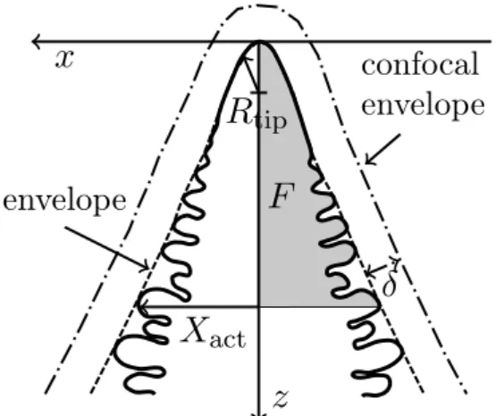
0 0.5 1 1.5 2 2.5 3 3.5 0.6 0.8 1 1.2 1.4 𝛿/𝑙diff= 𝛿 𝑉LGK/𝐷l 𝑉tip /𝑉 LGK 3DΩ0= 0.05 3DΩ0= 0.1 3DΩ0= 0.15 3DΩ0= 0.2 3DΩ0= 0.25Figure 1. Schematic illustration of the envelope, the confocal envelope, the envelope
width 𝑋act and the solid projection area 𝐹 of
an equiaxed dendrite.
Figure 2. Dependence of the predicted malised primary-tip velocity on the nor-malised stagnant-film thickness.
4th International Conference on Advances in Solidification Processes (ICASP-4) IOP Publishing IOP Conf. Series: Materials Science and Engineering 117 (2016) 012014 doi:10.1088/1757-899X/117/1/012014
(a) (b)
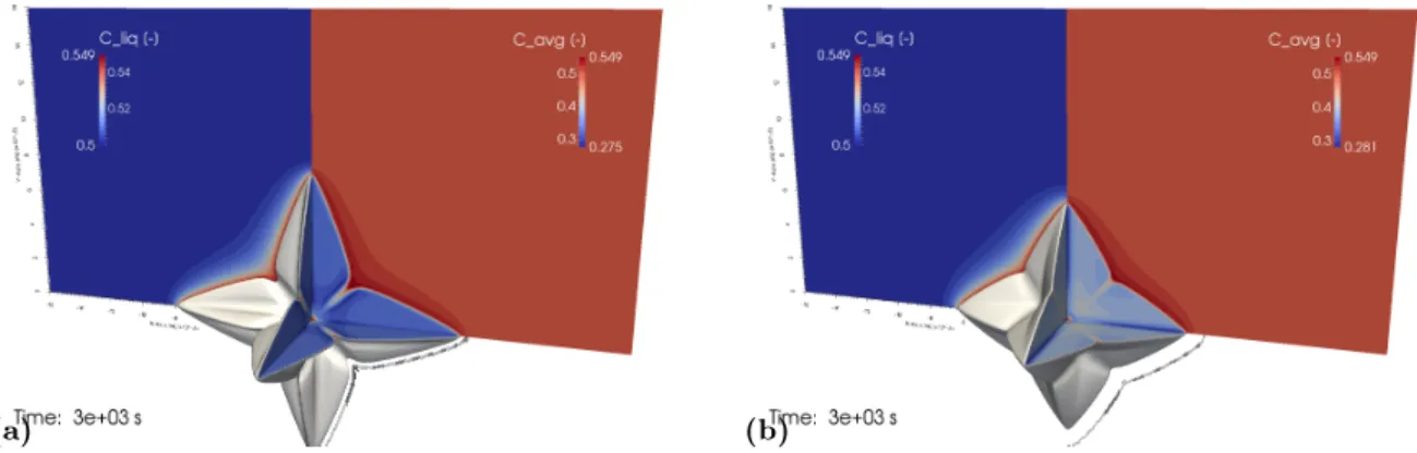
Figure 3. Comparisons of equiaxed grains growing at a supersaturation of Ω0 = 0.1for different
values of the stagnant-film thickness: (a) 𝛿/𝑅LGK= 5 and (b) 𝛿/𝑅LGK= 20.
that the natural convection did not significantly affect the envelope shape in the experiments of Melendez and Beckermann.
We are interested in the tip velocity, the envelope shape, and the solid fraction in the steady state of the dendrite envelope. We can consider that the steady state is reached when both the primary-tip velocity and the envelope shape no longer vary. The theoretical tip velocity
and radius, 𝑉LGK and 𝑅LGK, are calculated with the LGK model, using the same tip selection
parameter 𝜎*= 0.02as in the mesoscopic simulations. For purely solutal growth this corresponds
to using Eqs. (1–2) with an infinite stagnant-film thickness 𝛿.
The dependence of the primary tip velocity on the stagnant-film thickness for different supersaturations is shown in figure 2. We observed that the best way to scale the
stagnant-film thickness is by the diffusion length 𝑙diff = 𝐷l/𝑉LGK. We can see that the steady-state
primary tip velocity depends on 𝛿/𝑙diff due to the matching between the analytical solution and
the numerical solute diffusion field. Within a large range of supersaturations the error is less
than 20 % when 𝛿/𝑙diff > 1and less than 10 % when 𝛿/𝑙diff > 1.5.
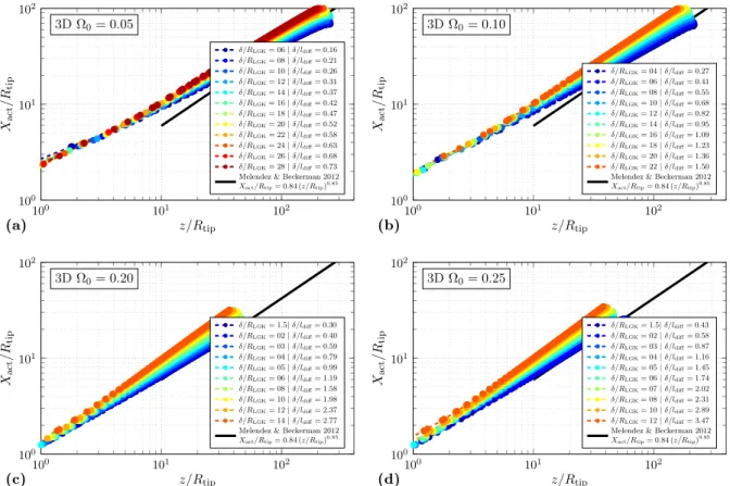
Similarly, if we consider the predicted shape of the equiaxed grains, we can notice in figure 3
that the dimensionless stagnant-film thickness 𝛿/𝑙diff significantly affects the shape of the grain
envelope. This influence can be studied by comparing our results with the scaling law determined by Melendez and Beckermann [8], which links the dimensionless sidebranch envelope widths
𝑋act/𝑅tip with the dimensionless longitudinal distance from the tip 𝑧/𝑅tip :
𝑋act 𝑅tip = 0.84 (︂ 𝑧 𝑅tip )︂0.85 (5) Except near the tip, where the mesoscopic envelope has no physical meaning, the computed envelopes are in relatively good agreement with the experiments. As can be seen in figure 4,
the agreement is better when 𝛿/𝑙diff ≤ 1. However, with a too small stagnant-film thickness, the
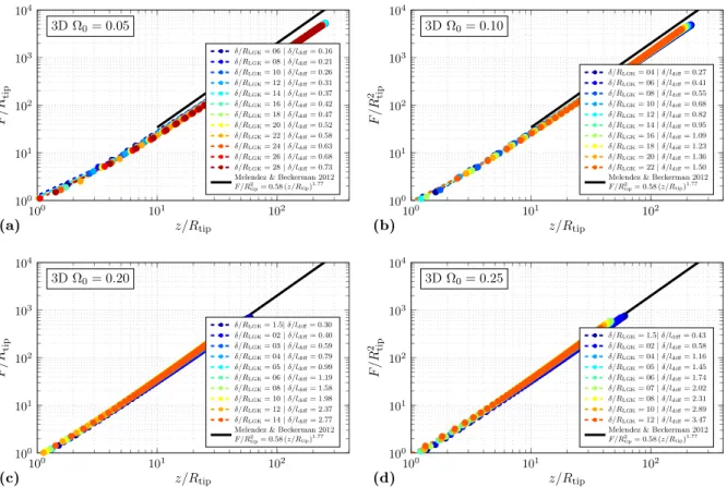
computed primary-tip velocity becomes less accurate and thus a compromise has to be made. Melendez and Beckermann [8] determined another interesting scaling law for the projected area 𝐹 of the solid dendrite structure:
𝐹 𝑅2 tip = 0.58 (︂ 𝑧 𝑅tip )︂1.77 (6) In our case, this projected area is obtained by first extracting the plane of the ridge of the sidebranches, (i.e. the plane at 𝑦 = 0) and then calculating the area integral of the solid fraction
100 101 102 100 101 102 𝑧/𝑅tip 𝑋act /𝑅 tip 3DΩ0= 0.05 𝛿/𝑅LGK= 06 | 𝛿/𝑙diff= 0.16 𝛿/𝑅LGK= 08 | 𝛿/𝑙diff= 0.21 𝛿/𝑅LGK= 10 | 𝛿/𝑙diff= 0.26 𝛿/𝑅LGK= 12 | 𝛿/𝑙diff= 0.31 𝛿/𝑅LGK= 14 | 𝛿/𝑙diff= 0.37 𝛿/𝑅LGK= 16 | 𝛿/𝑙diff= 0.42 𝛿/𝑅LGK= 18 | 𝛿/𝑙diff= 0.47 𝛿/𝑅LGK= 20 | 𝛿/𝑙diff= 0.52 𝛿/𝑅LGK= 22 | 𝛿/𝑙diff= 0.58 𝛿/𝑅LGK= 24 | 𝛿/𝑙diff= 0.63 𝛿/𝑅LGK= 26 | 𝛿/𝑙diff= 0.68 𝛿/𝑅LGK= 28 | 𝛿/𝑙diff= 0.73
Melendez & Beckerman 2012 𝑋act/𝑅tip= 0.84 (𝑧/𝑅tip)0.85
(a) 10 0 101 102 100 101 102 𝑧/𝑅tip 𝑋act /𝑅 tip 3DΩ0= 0.10 𝛿/𝑅LGK= 04 | 𝛿/𝑙diff= 0.27 𝛿/𝑅LGK= 06 | 𝛿/𝑙diff= 0.41 𝛿/𝑅LGK= 08 | 𝛿/𝑙diff= 0.55 𝛿/𝑅LGK= 10 | 𝛿/𝑙diff= 0.68 𝛿/𝑅LGK= 12 | 𝛿/𝑙diff= 0.82 𝛿/𝑅LGK= 14 | 𝛿/𝑙diff= 0.95 𝛿/𝑅LGK= 16 | 𝛿/𝑙diff= 1.09 𝛿/𝑅LGK= 18 | 𝛿/𝑙diff= 1.23 𝛿/𝑅LGK= 20 | 𝛿/𝑙diff= 1.36 𝛿/𝑅LGK= 22 | 𝛿/𝑙diff= 1.50
Melendez & Beckerman 2012 𝑋act/𝑅tip= 0.84 (𝑧/𝑅tip)0.85
(b) 100 101 102 100 101 102 𝑧/𝑅tip 𝑋act /𝑅 tip 3DΩ0= 0.20 𝛿/𝑅LGK= 1.5| 𝛿/𝑙diff= 0.30 𝛿/𝑅LGK= 02 | 𝛿/𝑙diff= 0.40 𝛿/𝑅LGK= 03 | 𝛿/𝑙diff= 0.59 𝛿/𝑅LGK= 04 | 𝛿/𝑙diff= 0.79 𝛿/𝑅LGK= 05 | 𝛿/𝑙diff= 0.99 𝛿/𝑅LGK= 06 | 𝛿/𝑙diff= 1.19 𝛿/𝑅LGK= 08 | 𝛿/𝑙diff= 1.58 𝛿/𝑅LGK= 10 | 𝛿/𝑙diff= 1.98 𝛿/𝑅LGK= 12 | 𝛿/𝑙diff= 2.37 𝛿/𝑅LGK= 14 | 𝛿/𝑙diff= 2.77 Melendez & Beckerman 2012 𝑋act/𝑅tip= 0.84 (𝑧/𝑅tip)0.85
(c) 10 0 101 102 100 101 102 𝑧/𝑅tip 𝑋act /𝑅 tip 3DΩ0= 0.25 𝛿/𝑅LGK= 1.5| 𝛿/𝑙diff= 0.43 𝛿/𝑅LGK= 02 | 𝛿/𝑙diff= 0.58 𝛿/𝑅LGK= 03 | 𝛿/𝑙diff= 0.87 𝛿/𝑅LGK= 04 | 𝛿/𝑙diff= 1.16 𝛿/𝑅LGK= 05 | 𝛿/𝑙diff= 1.45 𝛿/𝑅LGK= 06 | 𝛿/𝑙diff= 1.74 𝛿/𝑅LGK= 07 | 𝛿/𝑙diff= 2.02 𝛿/𝑅LGK= 08 | 𝛿/𝑙diff= 2.31 𝛿/𝑅LGK= 10 | 𝛿/𝑙diff= 2.89 𝛿/𝑅LGK= 12 | 𝛿/𝑙diff= 3.47 Melendez & Beckerman 2012 𝑋act/𝑅tip= 0.84 (𝑧/𝑅tip)0.85
(d)
Figure 4. Dimensionless sidebranch envelope width 𝑋act/𝑅tipas a function of the dimensionless
longitudinal distance from the tip 𝑧/𝑅tip and its sensitivity to the stagnant-film thickness 𝛿 for
four different supersaturations: (a) Ω0= 0.05, (b) Ω0 = 0.10, (c) Ω0= 0.20 and (d) Ω0= 0.25.
as a function of the distance from the primary tip in this plane. With the notations of figure 1, the projected area is calculated using the formula:
𝐹 (𝑧) = ∫︁ 𝑧 0 (︃ 1 𝑋act(𝑧) ∫︁ 𝑋act(𝑧) 0 𝑔s(𝑥, 𝑧) d𝑥 )︃ 𝑋act(𝑧) d𝑧 = ∫︁ 𝑧 0 ∫︁ 𝑋act(𝑧) 0 𝑔s(𝑥, 𝑧) d𝑥 d𝑧 (7)
In figure 5, we can see that the internal solid fraction is in very good agreement with the experiments. The exponent factor of the scaling law is very close to the experimentally
determined value. For high supersaturations, namely Ω0 = 0.2and Ω0 = 0.25, the pre-factor is
also similar. Moreover, we can note that the stagnant-film thickness has little influence on the
projected area and finally we can recommend 𝛿/𝑙diff = 1as a good compromise to obtain realistic
simulations with the mesoscopic envelope-field model in terms of envelope shape, internal solid fraction and primary-tip velocity.
4. Conclusions and perspectives
The mesoscopic envelope-field model of solidification gives physically realistic results for equiaxed dendritic growth in binary alloys. We have shown this by comparisons of three-dimensional simulations to experimental results for a wide range of undercoolings. The model can correctly approximate the velocity of both primary and secondary dendrite arms (i.e. the envelope shape) as well as the internal solid fraction in the envelope. To obtain accurate predictions, a proper choice of the stagnant-film thickness, a model parameter, is required. We have shown that a
4th International Conference on Advances in Solidification Processes (ICASP-4) IOP Publishing IOP Conf. Series: Materials Science and Engineering 117 (2016) 012014 doi:10.1088/1757-899X/117/1/012014
100 101 102 100 101 102 103 104 𝑧/𝑅tip 𝐹 /𝑅 2 tip 3DΩ0= 0.05 𝛿/𝑅LGK= 06 | 𝛿/𝑙diff= 0.16 𝛿/𝑅LGK= 08 | 𝛿/𝑙diff= 0.21 𝛿/𝑅LGK= 10 | 𝛿/𝑙diff= 0.26 𝛿/𝑅LGK= 12 | 𝛿/𝑙diff= 0.31 𝛿/𝑅LGK= 14 | 𝛿/𝑙diff= 0.37 𝛿/𝑅LGK= 16 | 𝛿/𝑙diff= 0.42 𝛿/𝑅LGK= 18 | 𝛿/𝑙diff= 0.47 𝛿/𝑅LGK= 20 | 𝛿/𝑙diff= 0.52 𝛿/𝑅LGK= 22 | 𝛿/𝑙diff= 0.58 𝛿/𝑅LGK= 24 | 𝛿/𝑙diff= 0.63 𝛿/𝑅LGK= 26 | 𝛿/𝑙diff= 0.68 𝛿/𝑅LGK= 28 | 𝛿/𝑙diff= 0.73 Melendez & Beckerman 2012 𝐹/𝑅2 tip= 0.58 (𝑧/𝑅tip)1.77 (a) 10 0 101 102 100 101 102 103 104 𝑧/𝑅tip 𝐹 /𝑅 2 tip 3DΩ0= 0.10 𝛿/𝑅LGK= 04 | 𝛿/𝑙diff= 0.27 𝛿/𝑅LGK= 06 | 𝛿/𝑙diff= 0.41 𝛿/𝑅LGK= 08 | 𝛿/𝑙diff= 0.55 𝛿/𝑅LGK= 10 | 𝛿/𝑙diff= 0.68 𝛿/𝑅LGK= 12 | 𝛿/𝑙diff= 0.82 𝛿/𝑅LGK= 14 | 𝛿/𝑙diff= 0.95 𝛿/𝑅LGK= 16 | 𝛿/𝑙diff= 1.09 𝛿/𝑅LGK= 18 | 𝛿/𝑙diff= 1.23 𝛿/𝑅LGK= 20 | 𝛿/𝑙diff= 1.36 𝛿/𝑅LGK= 22 | 𝛿/𝑙diff= 1.50 Melendez & Beckerman 2012 𝐹/𝑅2 tip= 0.58 (𝑧/𝑅tip)1.77 (b) 100 101 102 100 101 102 103 104 𝑧/𝑅tip 𝐹 /𝑅 2 tip 3DΩ0= 0.20 𝛿/𝑅LGK= 1.5| 𝛿/𝑙diff= 0.30 𝛿/𝑅LGK= 02 | 𝛿/𝑙diff= 0.40 𝛿/𝑅LGK= 03 | 𝛿/𝑙diff= 0.59 𝛿/𝑅LGK= 04 | 𝛿/𝑙diff= 0.79 𝛿/𝑅LGK= 05 | 𝛿/𝑙diff= 0.99 𝛿/𝑅LGK= 06 | 𝛿/𝑙diff= 1.19 𝛿/𝑅LGK= 08 | 𝛿/𝑙diff= 1.58 𝛿/𝑅LGK= 10 | 𝛿/𝑙diff= 1.98 𝛿/𝑅LGK= 12 | 𝛿/𝑙diff= 2.37 𝛿/𝑅LGK= 14 | 𝛿/𝑙diff= 2.77 Melendez & Beckerman 2012 𝐹/𝑅2 tip= 0.58 (𝑧/𝑅tip)1.77 (c) 10 0 101 102 100 101 102 103 104 𝑧/𝑅tip 𝐹 /𝑅 2 tip 3DΩ0= 0.25 𝛿/𝑅LGK= 1.5| 𝛿/𝑙diff= 0.43 𝛿/𝑅LGK= 02 | 𝛿/𝑙diff= 0.58 𝛿/𝑅LGK= 04 | 𝛿/𝑙diff= 1.16 𝛿/𝑅LGK= 05 | 𝛿/𝑙diff= 1.45 𝛿/𝑅LGK= 06 | 𝛿/𝑙diff= 1.74 𝛿/𝑅LGK= 07 | 𝛿/𝑙diff= 2.02 𝛿/𝑅LGK= 08 | 𝛿/𝑙diff= 2.31 𝛿/𝑅LGK= 10 | 𝛿/𝑙diff= 2.89 𝛿/𝑅LGK= 12 | 𝛿/𝑙diff= 3.47 Melendez & Beckerman 2012 𝐹/𝑅2
tip= 0.58 (𝑧/𝑅tip)1.77
(d)
Figure 5. Normalised projection area 𝐹/𝑅2
tip as a function of the dimensionless longitudinal
distance from the tip 𝑧/𝑅tipand its sensitivity to the stagnant-film thickness 𝛿 for four different
supersaturations: (a) Ω0 = 0.05, (b) Ω0 = 0.10, (c) Ω0 = 0.20 and (d) Ω0 = 0.25
stagnant-film thickness of the order of the primary-tip diffusion length 𝐷l/𝑉tipleads to accurate
predictions of the dynamics, of the shape and of the internal solid fraction of equiaxed grains. Upcoming work will consist of studying interactions between grains with multiple orientations, and of modeling of natural and forced convection, as well as of convection due to grain settling. Acknowledgement
This work was supported by the French State through the program “Investment in the future” operated by the National Research Agency (ANR), referenced by ANR-11 LABX-0008-01 (LabEx DAMAS) and by NASA under grant number NNX14AD69G.
References
[1] Rappaz M and Gandin C A 1993 Acta Metall. Mater. 41 345–360 [2] Zhu M F and Hong C P 2001 ISIJ Int. 41 436–445
[3] Kharicha A, Stefan-Kharicha M, Wu M and Ludwig A 2012 IOP Conf. Ser. Mater. Sci. Eng. 33 12115 [4] Tourret D and Karma A 2013 Acta Mater. 61 6474–6491
[5] Steinbach I, Beckermann C, Kauerauf B, Li Q and Guo J 1999 Acta Mater. 47 971–982 [6] Steinbach I, Diepers H J and Beckermann C 2005 J. Cryst. Growth 275 624–638 [7] Delaleau P, Beckermann C, Mathiesen R H and Arnberg L 2010 ISIJ Int. 50 1886–1894 [8] Melendez A J and Beckermann C 2012 J. Cryst. Growth 340 175–189
[9] Cantor B and Vogel A 1977 J. Cryst. Growth 41 109–123 [10] Sun Y and Beckermann C 2007 J. Comput. Phys. 220 626–653 [11] Beckermann C and Viskanta R 1993 Appl. Mech. Rev. 46 1–27