HAL Id: in2p3-00169415
http://hal.in2p3.fr/in2p3-00169415
Submitted on 3 Sep 2007
HAL is a multi-disciplinary open access
archive for the deposit and dissemination of
sci-entific research documents, whether they are
pub-lished or not. The documents may come from
teaching and research institutions in France or
abroad, or from public or private research centers.
L’archive ouverte pluridisciplinaire HAL, est
destinée au dépôt et à la diffusion de documents
scientifiques de niveau recherche, publiés ou non,
émanant des établissements d’enseignement et de
recherche français ou étrangers, des laboratoires
publics ou privés.
3-D magnetic calculation methods for SPIRAL scaling
FFAG magnet design
T. Planche, D. Neuvéglise, J.-L. Lancelot, J. Fourrier, J. Pasternak, E.
Froidefond, B. Autin, F. Méot
To cite this version:
T. Planche, D. Neuvéglise, J.-L. Lancelot, J. Fourrier, J. Pasternak, et al.. 3-D magnetic calculation
methods for SPIRAL scaling FFAG magnet design. 22nd Particle Accelerator Conference (PAC’07),
Jun 2007, Albuquerque, New Mexico, United States. Joint Accelerator Conferences Website; IEEE,
pp.1401-1403, 2007. �in2p3-00169415�
3-D MAGNETIC CALCULATION METHODS FOR SPIRAL SCALING
FFAG MAGNET DESIGN
T. Planche*, D. Neuvéglise, J.-L Lancelot, SIGMAPHI, Vannes (France)
J. Fourrier, J. Pasternak, E. Froidefond, B. Autin, CNRS/IN2P3/LPSC, Grenoble (France)
F. Méot, CEA&IN2P3, LPSC, Grenoble (France)
Abstract
2-D and 3-D magnetic calculation tools and methods have been developed at SIGMAPHI, in collaboration with IN2P3/LPSC, to design spiral FFAG (Fixed Field Alternating Gradient) magnets. These tools are currently being used for RACCAM spiral scaling FFAG magnet design. In the particular case of a spiral gap shaped magnet, a careful magnetic design has to be realized in order to keep both vertical and horizontal tunes constant during acceleration process. Promising results, obtained from tracking in 3-D field maps, demonstrate the efficiency of the horizontal and vertical tune adjustment methods presented in this paper.
INTRODUCTION
Possibilities offered by FFAG accelerators are of great interest for many applications, like proton [1] or ion beam production, medical neutron (BNCT) [2], spallation source for subcritical reactor operation [3] and unstable particle beam acceleration [4][5]. FFAG accelerators are thus, since the beginning of this decade [6], subject to intense research and development activities.
In line with this renewed interest for FFAG, RACCAM project [7] arose from the collaboration between a CNRS laboratory – IN2P3/LPSC, the nuclear medicine Department of Grenoble Hospital, and a French industrial – SIGMAPHI. The purpose of this project is to design and realise a prototype of spiral magnet being the elementary cell of a medical scaling FFAG proton ring.
Two different and complementary magnet designs have been considered. Both are spiral magnets, but the B0(R/R0)k radial field law needed to fulfil the scaling
conditions [8] is obtained via different technical solutions. The first solution, based on gap shaped magnet technology is being studied at SIGMAPHI.
The other one uses a parallel pole (constant gap) magnet with distributed coils on the pole to obtain the right field law. This solution is being studied at IN2P3/LPSC.
The purpose of this paper is to present the 2-D and 3-D calculation tools and methods developed for the design of a gap shaped spiral scaling FFAG magnet, as well as the encouraging preliminary results obtained.
WORKING HYPOTHESIS
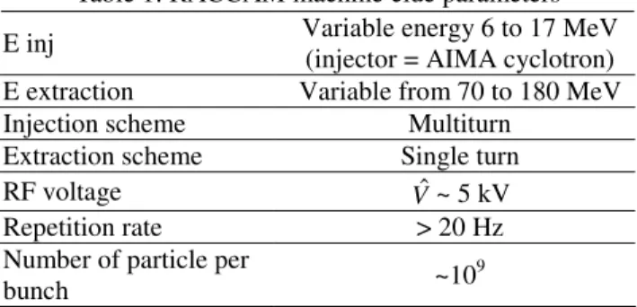
A realistic magnet design has to take properly into account considerations like beam dynamics, lattice aspects, acceleration methods, injection and extraction scheme and radioprotection issues. This is under study at IN2P3/LPSC. Related to these constraints nominal values of clue parameters were chosen for RACCAM magnet design (see Table 1).
E inj Variable energy 6 to 17 MeV (injector = AIMA cyclotron) E extraction Variable from 70 to 180 MeV Injection scheme Multiturn
Extraction scheme Single turn RF voltage Vˆ ~ 5 kV
Repetition rate > 20 Hz Number of particle per
bunch ~10
9
Table 1: RACCAM machine clue parameters
MAGNETIC CALCULATION ISSUES
Beam Dynamics Considerations
One of the purposes of magnetic calculation is to produce accurate 3-D field maps. After tracking in these field maps, using Zgoubi tracking code [9], the aim is to identify at least one set of parameters and technological choices that give a dynamical aperture several times larger than the emittance required.
A horizontal emittance of 40 π.mm.mrad, ensuing from a multiturn injection process, has been chosen as a nominal value. Vertical emittance can be less. With the repetition rate and the number of particles per bunch shown in Table 1, it provides a dose delivery rate of about 5 Gy/min.per liter.
Technological considerations
Vertical focusing can, in the smooth approximation [10][11], be written as ) ) cos( . )) ( sin 1 .( . tan( 1 1 2
ε
ρ
ε
λ
ε
ρ
− + IWhere ρ is the radius of curvature, ε is the edge angle,
∫
−+∞∞−
=
2 0 0 1.
))
(
).(
(
B
g
s
B
B
s
B
I
, with B0 the value of B(s) wellinside the magnet and g the magnetic gap height. λ is a distance characteristic of the fringe field extent, which
___________________________________________ *[email protected]
Proceedings of PAC07, Albuquerque, New Mexico, USA TUPAN007
04 Hadron Accelerators
1-4244-0917-9/07/$25.00 c 2007 IEEE
A12 FFAG, Cyclotrons
can be taken in first approximation equal to g. I1 and ε are
supposed constant with radius (i.e. constant with energy). Since ρ is proportional to the machine radius R, the fringe field length λ has to increase linearly with R to keep the vertical focusing constant with energy.
However, in the case of gap shaped magnet, the magnet physical gap g decreases with radius to create the B0(R/R0)k field law. This contradictory behaviour leads to
a significant increase in vertical tune with energy that can cause neighbouring of dangerous resonances during acceleration process.
One can then understand why a solution with constant gap and distributed currents fits a priori better the vertical scaling condition. Preliminary studies tend to show that this solution needs a significantly larger amount of current. This is currently being studied at IN2P3/LPSC.
The aim of the RACCAM project is also to design a machine of reasonable cost, compared with commercial medical cyclotrons. This constraint led us to study in detail the gap shaping solution.
2-D AND 3-D MAGNETIC
CALCULATIONS WITH TOSCA
Every 2-D and 3-D computation described in this paper was done using OPERA (version 11).
2-D and 3-D models construction
Magnet optical parameters are determined with the help of spiral FFAG lattice design tools [12] developed at IN2P3/LPSC. From these ideal optical parameters, model geometry and properties are defined in OPERA-Modeller using a set of OPERA-command files, written at SIGMAPHI especially for FFAG magnet design purposes.
Model boundaries
The model is surrounded by an air background. On the external faces of this background, three different types of boundary conditions are applied.
The up and down symmetry of the magnet allow us to use Normal Magnetic boundary conditions along the median plan (Z = 0).
Figure 1: 3-D OPERA Model boundary conditions.
The machine periodicity leads us to use Periodic Azimuthally (2π/Number of cells periodic) boundary conditions. These conditions are applied along cut planes located in the middle of the drifts (Figure 1) [13].
On the other background faces “Far boundary” conditions are applied.
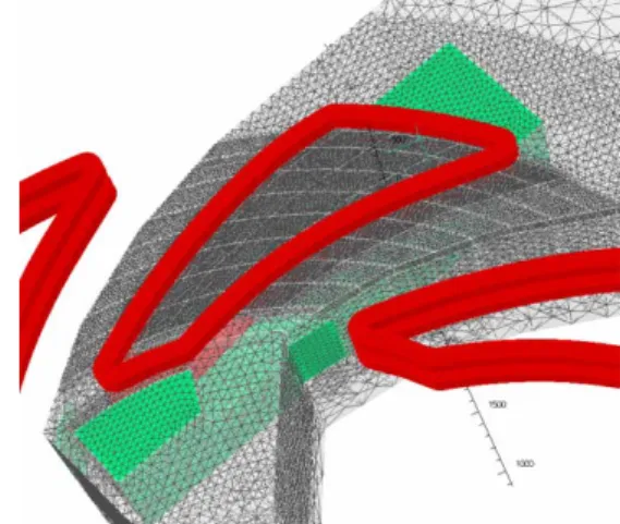
3-D Model mesh
A set of air boxes is used to define a mesh size adapted to each field region. Several precautions have to be taken to allow OPERA tetrahedrical mesh generator to go through its task. Mesh constraints, created on the interface between two regions of different mesh size, have to be limited. A maximum factor 3 in mesh size between two nearby cells is a good criterion. Adapted geometry cuts are used to help the mesh generator to deal with the complicated iron yoke shape.
Figure 2: Details of 3-D model mesh
Magnet design
An iterative approach is used to carry out the magnet design. Interlinked 2-D and 3-D calculations were developed for this purpose.
An automated 2-D iterative process determines the needed pole shape in the magnet mid-plane. Then a 3-D spiral magnet model, based on the previous gap shape law, is automatically constructed. After computation, vertical B field values in the magnet center at every radius are obtained. The difference with the theoretical radial field law is then used as input to another series of 2-D automated calculations, which leads to the determination of a new pole shape. A new 3-D model is generated, and so on. This iterative process converges after about 2 or 3 iterations to a relative field quality better than 1.10-4 in the good field region.
The magnetic spiral shape is also corrected using a 3-D iterative process. Vertical B field integral is calculated in 3-D models along reference trajectories (particle trajectory in smooth approximation) on each side of the magnet. The mechanical spiral is then bent to obtain the right effective length at each radius, and thus the right magnetic spiral shape. This process is not assisted by rapid 2-D iterations and takes between 6 and 9 iterations
Normal Magnetic
2π/N Periodicity
Yoke
TUPAN007 Proceedings of PAC07, Albuquerque, New Mexico, USA
04 Hadron Accelerators
1402
A12 FFAG, Cyclotrons
to converge to a relative precision of 1.10-3 on effective length values.
VERTICAL TUNE SHIFT REDUCTION
As seen above, the link of proportionality between the fringe field extent λ and the gap size is a source of significant vertical tune shift. In order to get a constant vertical tune, we need to adjust the fringe field (keeping the right effective length) for every radius.
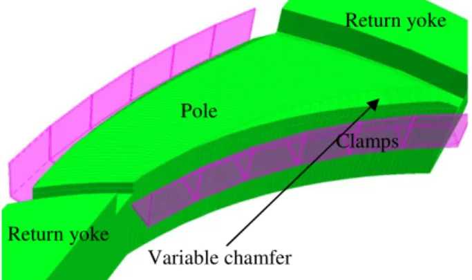
Figure 3: OPERA 3-D Model of a spiral gap shaped magnet with variable chamfer and field clamps. The decrease in fringe field extent due to the gap narrowing is compensated by an increase in chamfer height. This is all the more efficient as the gap is low.
On the other hand, in high gap regions, clamps efficiently reduce the fringe field length.
That way we increase λ linearly with R, and thus correct the natural vertical tune shift.
This technological solution has been simulated in 3-D (Model shown Figure 3) to produce a 3-D field map.
Tracking with Zgoubi code [9] has validated this solution (see Figure 4), vertical tune variation has been reduced by a factor 2.
Figure 4: Horizontal (Qx) and vertical (Qz) tune versus Energy (MeV) from tracking in 3-D field maps.
The remaining chaotic tune variations may be attributed with the magnetic effective lengths that are not yet adjusted accurately enough (relative precision of 1.10-3). This will be improved soon, continuing the design iterative process.
CONCLUSION
Efficient 3-D simulation tools have been developed to design spiral FFAG magnets. With a careful magnetic design, the gap shaping solution seems compatible with the constant tune condition. We will soon be able to produce the final design of RACCAM magnet and start the manufacturing of the prototype.
REFERENCES
[1] Study of Compact Medical FFAG Accelerators, Toshiyuki Misu, FFAG04 worshop, KEK, Tsukuba, http://hadron.kek.jp/FFAG/FFAG04_HP/index.html. [2] Study of Compact Medical FFAG accelerators and
their applications for intense secondary particle production, Y.Mori, NIM A 562-2, 23 June 2006, 591-595.
[3] Construction of FFAG Accelerator in Kurri for ADS study, M. Tanigaki, K. Mishima, S. Shiroya, Y. Ishi, S. Fukumoto, S. Machida, Y. Mori, M. Inoue, Proceedings of EPAC 2004, Lucerne, Switzerland [4] Non-Scaling FFAG lattice design for the Radioactive
Ion Accelerator, D. Trbojevic, FFAG07 Worskop, Grenoble, France,
http://lpsc.in2p3.fr/congres/FFAG07/.
[5] A feasibility study of a neutrino factory in Japan, KEK report, February 2001
[6] The rebirth of FFAG, M. Craddock, CERN Courrier 44-6 (2004)
[7] The FFAG R&D and Medical application project RACCAM, B. Autin, J. Collot, J. Fourrier, E. Froidefond, F. Martinache, F. Méot, J. Balosso, J.-L. Lancelot, D. Neuvéglise, Proceedings of EPAC 2006, Edinburg, Scotland.
[8] The FFAG synchrotron Mark I , K.R. Symon, MURAS-KRS et al., MURADWK/KMT/LWJ/KRS-3, Nov (1954)
[9] Zgoubi user’s guide (v4.3), F. Méot, S. Valero, Rapport DAPNIA-02-395
[10] A First and Second-Order Matrix Theory for the Design of Beam Transport Systems and Charged Particle Spectrometers, Karl L. Brown, SLAC-75 [11] Développement de codes de simulation de FFAG spiral et programmes d’automatisation de balayage de paramètres dans le cadre du projet RACCAM , J. Fourrier, internal report LPSC 07-47 (2007) [12] Spiral FFAG lattice design tools Application to 6-D
tracking, J. Fourrier, F. Martinache, F. Méot, J. Pasternak, IN2P3/LPSC internal report submitted to NIM, May 2007
[13] W. Beeckman (IBA), Private communications, FFAG07 Workshop, Grenoble, France
Pole
Variable chamfer
Clamps
Return yoke
Return yoke
Proceedings of PAC07, Albuquerque, New Mexico, USA TUPAN007
04 Hadron Accelerators
1-4244-0917-9/07/$25.00 c 2007 IEEE
A12 FFAG, Cyclotrons