HAL Id: cea-02438338
https://hal-cea.archives-ouvertes.fr/cea-02438338
Submitted on 14 Jan 2020HAL is a multi-disciplinary open access archive for the deposit and dissemination of sci-entific research documents, whether they are pub-lished or not. The documents may come from teaching and research institutions in France or abroad, or from public or private research centers.
L’archive ouverte pluridisciplinaire HAL, est destinée au dépôt et à la diffusion de documents scientifiques de niveau recherche, publiés ou non, émanant des établissements d’enseignement et de recherche français ou étrangers, des laboratoires publics ou privés.
Thermal-Hydraulics Calculation Schemes for SFR
Applications at CEA
A. Gerschenfeld, S. Li, Y. Gorsse, R. Lavastre
To cite this version:
A. Gerschenfeld, S. Li, Y. Gorsse, R. Lavastre. Development and Validation of Multi-scale Thermal-Hydraulics Calculation Schemes for SFR Applications at CEA. International Conference on Fast Reac-tors and Related Fuel Cycles Next Generation Nuclear Systems for Sustainable Development (FR17), Jun 2017, Yekaterinburg, Russia. �cea-02438338�
Development and Validation of Multi-Scale Thermal-Hydraulics
Calculation Schemes for SFR Applications at CEA
A. Gerschenfeld1, S. Li1, Y. Gorsse1, R. Lavastre2
1 DEN-Service de Thermohydraulique et de Mécanique des Fluides, STMF, CEA, Université
Paris-Saclay,F-91191 Gif-sur-Yvette, France
2 Commissariat à l’Energie Atomique et aux Energies Alternatives, CEA, Département
d’Etudes des Réacteurs, 13108 Saint-Paul-Lez-Durance, France
E-mail contact of main author: [email protected]
Abstract. In the framework of the ASTRID project for a Generation IV SFR, extensive R&D efforts are under way to improve and better validate the SFR thermal-hydraulics codes available at CEA. These efforts include : − The development and validation of SFR-specific models in CATHARE. Developed at CEA, CATHARE is
the current reference STH code for French LWR safety studies : SFR-specific developments are being integrated and validated into the lastest version of the code, CATHARE3.
− The development and validation of TrioMC, a subchannel code specific to SFR core thermal-hydraulics. Initially created for design studies (with the aim of computing the maximum cladding temperature of a given core flow-rate map), TrioMC has been upgraded in order to compute the local behavior of the core during accidental transients.
− The application and validation of TrioCFD, a 3D, staggered-mesh CFD code developed at CEA, to SFR studies. TrioCFD is being used to compute flow behavior in the large plena of pool-type SFRs (hot and cold pools), as well as in the IHX primary side and in the in-core inter-wrapper gap regions.
In most cases, these codes are used independently. However, in some cases, local phenomena may have a strong feedback effect on the global behavior of the reactor : for instance, during passive decay-heat removal by natural convection, flows in the inter-wrapper gaps may contribute to up to 30% of the overall DHR if the heat sink is provided by DHXs in the hot pool. The strength of this contribution leads to a feed-back effect from a local (subchannel/CFD) phenomenon) to the global (system) scale.
In order to model such effects, a coupling between CATHARE, TrioMC and TrioCFD has been developed at CEA and integrated into a new code : MATHYS (Multiscale ASTRID Thermal-HYdraulics Simulation). Within MATHYS, TrioMC and TrioCFD are coupled at their boundaries (core outlet and hex-can sides), using a domain-decomposition approach : then, the two codes are coupled with a CATHARE simulation of the complete system using a domain-overlapping method. The resulting multi-scale simulation is able to account for feedback effects between all three scales.
This paper first outlines the development and validation efforts related to CATHARE, TrioMC and TrioCFD; then, the coupling algorithm underlying MATHYS is described. The final section discusses the validation of MATHYS : overall approach, validation of coupled effects on existing experiments (TALL-3D for STH/CFD, PLANDTL-DHX for subchannel/CFD, PHENIX at the integral scale).
Key Words: thermal-hydraulics, natural convection, multiscale, CFD
1. Introduction
Launched in 2006, the ASTRID project (Advanced Sodium Technology Reactor for Industrial Demonstration) [1] aims to design and construct a Generation IV, 600 MWe SFR in France. In 2016, the project entered its Basic Design (BD) phase.
Compared to the French SFRs PHENIX and SUPERPHENIX, ASTRID must satisfy a safety level at least equivalent to those of a GenIII reactor. Design changes are necessary to fulfill this objective; however, for a given design, the development of better safety assessment tools can also contribute to the demonstration of this high safety level. By reducing the uncertainty associated with the predictions of these calculation tools, the conservative margins used for the reactor's safety demonstration can be reduced.
Thus large R&D efforts have been dedicated at CEA to the development and validation of more predictive calculation tools for safety assessment. This is particularly the case for Thermal-Hydraulics (TH), as many safety-relevant transients for SFRs are determined by TH phenomena [2]: for instance, protected and unprotected Loss-Of-Flow transients (LOF and ULOF), as well as the ability to passively remove decay heat, are strongly affected by the behavior of natural convection in the primary circuit. Hence, improving the prediction of SFR primary circuit thermal-hydraulics in accidental conditions has been the subject of considerable efforts.
In such conditions, the overall behavior of the reactor is the product of complex interactions between TH phenomena occurring at different scales, from recirculation effects inside each sub-assembly in the core, to jet behavior in the hot and cold plena of the primary circuit, and to interactions with other reactor circuits (intermediate loops, DHR circuits). Calculation tools are being developed and validated at CEA in order to predict each of these phenomena:
− at the global reactor scale, the CATHARE [3] system-scale code, initially developed by CEA, AREVA, EDF and IRSN for LWR reference safety analysis, has been extended to SFR applications;
− at the local core scale, a subchannel code, TrioMC [4], has been developed to predict the local behavior of the core in design and accidental conditions;
− for other regions subjected to 3D phenomena (such as the hot and cold pools), a CFD code developed at CEA, TrioCFD [5], is being applied and validated.
Predicting interactions between these phenomena during an accidental transient presents a further challenge. Instead of developing a new standalone tool capable of describing all the potential relevant phenomena, it was decided in 2010 to model these interactions through a coupling between CATHARE, TrioMC and TrioCFD, in order to avoid the duplication of development and validation efforts. This strategy led to the development of a new tool, called MATHYS (Multi-Scale Astrid Thermal-Hydraulic Simulation): this tool can be used to perform a coupled transient calculation by two or more codes in a generic way, using a small input deck as input.
This paper is organized as follows:
− in a first part, the SFR-related development and validation activities for CATHARE, TrioMC and TrioCFD are summarized, and the current capabilities of these codes are described;
− a second part describes the development of coupling strategies between these codes, up to the development of MATHYS. A description of the coupling algorithms used in MATHYS is provided;
2. Development and Validation of CATHARE, TrioMC and TrioCFD for SFRs 2.1. CATHARE
CATHARE (Code Avancé de THermohydraulique Accidentelle des Réacteurs à Eau) is the reference system-scale thermal-hydraulics code for French LWR safety studies. Developed by CEA, AREVA, EDF and IRSN since 1979, it solves a two-phase, 6-equations model on a network of 0D, 1D and 3D elements, using a staggered discretization (velocities are defined at the faces between mesh cells) with a fully-implicit (0D/1D) or semi-implicit (3D) time scheme. The code also includes a point-kinetics model in order to predict the neutronic power evolution during a given transient.
In order to adapt CATHARE for SFR applications such as ASTRID, the following developments were undertaken: sodium physical properties and correlations were integrated, additional feedback parameters were added to code's neutronic model, SFR mechanical and EM pump models were added.
Simultaneously, a validation base has been constructed to cover these developments, ranging from analytical subassembly experiments such as GR19 [6], SIENA and SENSAS [7] to the analysis of reactor tests on the RAPSODIE, PHENIX [8], SUPERPHENIX and MONJU reactors.
Ongoing work includes the development of two-phase flow correlations and their validation on data from experiments in operation, such as AR-1[9]; the development of 0D and 1D mechanical pump models capable of predicting the onset of cavitation in primary pumps during pump-diagrid pipe break accidents; and the development and validation of functionalities required to model high-pressure nitrogen circuits, such as the 180atm N2
Brayton power conversion system currently selected for ASTRID [10]. Validation of these single-phase gas capabilities on gas loop and reactor data (from HEFUS, EVO and PBMM) will be complemented by the realization of a new nitrogen loop to study fast transients.
On the longer term, experimental results from component qualification experiments (for subassemblies, heat exchangers, pumps and PCS exchangers and turbomachines) will contribute to the validation of the relevant CATHARE models: the ASTRID thermal-hydraulic commissioning tests will also contribute to its validation.
2.2.TrioMC
Development of the TrioMC code (for "Modèle Cœur") started at CEA in 2009. Its initial aim was to provide a fast method to compute the maximum cladding temperature in a S/A for a given flow-rate, in order to optimize the flow-zone map of SFR cores. In order to avoid the cost of a geometry-resolved CFD while accounting for the strong radial gradient within a single S/A (up to 50°) [4], the subchannel scale was a natural choice for this code: at this scale, correlations must be used to account for the effect of the wire wrappers on bundle pressure drop and mixing between subchannels.
In order to avoid redundancy, TrioMC shares many common functions with the TrioCFD code also developed at CEA. Today, these common functions (which are also reused in MATHYS) have been open-sourced as a common thermal-hydraulics platform : TRUST. In line with the initial aims of the code, its initial solution method was a single-phase marching resolution adapted to steady-state forced-convection flows. However, the core safety criteria for accidental conditions are specified in terms of the maximum cladding temperature: hence, obtaining the subchannel-scale temperature field during transient
conditions was necessary. In turn, a new numerical method, suitable for transient and mixed/natural-convection flows, was integrated in the code in 2014.
In 2015, this method was extended to two-phase flows in order to model 3D boiling effects inside subassemblies. The current method uses a 6-equation, semi-implicit resolution on a staggered mesh: stabilizer equations, similar to those used in the TRACE SETS method [11] have been implemented in order to allow for large time steps. Correlations for two-phase mass, momentum and heat transfers were implemented, starting from the basis of the SABENA [12] code.
The validation database for TrioMC was extended together with these developments. In addition to 6 sub-assembly experiments in forced, mixed and natural convection, the GR19 [6] and ECONA experiments were used to validate two-phase flows in forced and natural convection. Additional validation will be made possible by the AR-1 experiment at IPPE [9]. At present, TrioMC can only model a single, triangular-lattice rod bundle in each S/A: efforts are under way to extend the code to arbitrary S/A geometries.
2.3.TrioCFD
In 1993, CEA started development of Trio_U, a parallelized CFD code with a modern C++ software architecture. This code includes numerical methods for solving single-phase flows on either structured Cartesian or unstructured tetrahedral meshes, using a staggered discretization: turbulence can be described using RANS and LES models. A Front-Tracking capability allows to describe liquid-gas interfaces explicitly.
In 2015, part of the Trio_U functions common to other projects, such as TrioMC (§2.2), were integrated into the open-source TRUST platform. The remaining functions were integrated into the TrioCFD code itself.
Efforts to extend the validation database of TrioCFD to sodium applications started in 2006: − the modeling of wire-wrapped S/As was validated against the PLANDTL-37J and
Lafay experiments [14];
− predictions of jet and stratification behavior were validated on the CORMORAN and SUPERCAVNA experiments (at the analytical scale), on the PLANDTL-DHX [13] experiment (at an intermediate scale) and on the MONJU and PHENIX [8] reactors (at the integral scale);
− predictions of free surface behavior were tested on the BANGA experiment;
− prediction of thermal striping phenomena using LES has been validated on the PLAJEST experiment in the framework of a benchmark with JAEA and ANL [16]. Data from the PLATEAU facility [17] for large-scale water mockups will then be used to further validate TrioCFD : currently, this facility houses the MICAS experiment, a 1/6th model of the ASTRID hot pool.
3. Development of coupled thermal-hydraulics models 3.1 Supervisor-based coupling
The initial impulsion to develop coupled models for SFR thermal-hydraulics at CEA arose from the following cases :
1) In order to assess the mechanical equilibrium of the core in normal operation, the local temperature of the S/A hexcans must be determined. In order to obtain this temperature field, the inter-wrapper region must be modelled. Such a model can be easily constructed in CFD: however, only TrioMC can provide a 3D model of all subassemblies (a CFD model of the complete core remains infeasible). Hence it was natural to develop a coupling between TrioMC and TrioCFD.
2) Reactor transients leading to natural convection (such as a LOF) are strongly affected by 3D flow phenomena in the large plena of the primary circuit. The core outlet jet (in the hot pool) and the IHX outlet jets (in the cold pool) deviate upwards because of buoyancy effects as the flow decreases: on the longer term, both pools undergo strong stratification. Historically, such effects have been modelled using conservative estimates calibrated on geometrically-accurate water mock-ups: however, numerical advances make it possible to describe these phenomena directly in CFD.
However, developing a CFD model of the complete primary circuit would entail a large numerical cost as well as considerable development efforts. Therefore, an approach where the system-scale model could be used with the exception of specific regions (such as the hot and cold pool) was considered preferable.
As a first step, a common coupling interface, called ICoCo, was implemented in CATHARE, TrioMC and TrioCFD. This interface makes it possible to use each code as a callable library through C function calls: these calls allow a small C++ or Python program, known as the "supervisor" to perform and control a calculation, by :
− setting the value of the code's next time step ("initTimeStep(...)"), solving it ("solveTimeStep(...)") and either advancing the simulation ("validateTimeStep(...)") or resetting the code to its previous state ("abortTimeStep()");
− in between these function calls, either obtaining internal data from the code (function "getOutputField()") or modifying it with outside values ("setInputField()").
Using this interface, supervisor programs could be written to perform coupled calculations on a per-case basis. The computation of hex-can temperatures in nominal state (1) was addressed by a supervisor-based coupling between TrioMC (core) and TrioCFD (IWR + hot pool); while a coupling between CATHARE (for the complete primary circuit) and TrioCFD (for the hot and cold pool) was developed to study the effect of 3D pool phenomena on natural convection in the PHENIX [8] and ASTRID cases.
During this "first phase" of coupling development, these use cases demonstrated the importance of accounting for coupled effects. Several shortcomings of the supervisor approach were also highlighted:
− for each new case, designing or adapting a suitable supervisor was a considerable source of lost time and errors. This supervisor must be compiled for each calculation, so each coupling user needs a functional development environment;
− there was no verification of input data consistency (for instance, that the geometries of various elements are consistent between codes at their coupling interfaces);
− the coupling algorithms validated on a given case (such as the PHENIX natural convection test) were not guaranteed to be the same as those used for applications. Together, these difficulties led to a considerable user effect and cast doubt on the possibility of validating a supervisor-based coupling. In turn, they led to the development of the MATHYS integrated coupling, described below.
3.2 Integrated coupling: MATHYS
In order to solve the issues with supervisor-based coupling outlined above, development of a "generic" coupling between CATHARE, TrioMC and TrioCFD started in 2015. Known as MATHYS (Multi-Scale Astrid Thermal-Hydraulic Simulation), this code uses the same ICoCo coupling interface as supervisor-based coupling : however, compared to a per-case supervisor, the MATHYS is a fixed code and obtains case-specific information from a small input deck. Like TrioMC and TrioCFD, MATHYS is based on the TRUST platform, which allows for the re-use of common capabilities (such as input deck parsing, mesh manipulation, etc.). This structure solves most difficulties associated with supervisor-based coupling:
− MATHYS can be easily applied to a new case by changing its input deck to specify the relevant coupling interfaces. As the code is fixed, no recompilation is necessary; − automatic verification is performed to ensure geometrical consistency between the
different codes;
− the coupling algorithms used by MATHYS (described below) are the same between all cases. Therefore the algorithms used for reactor applications are guaranteed to be the same as those used for validation experiments.
In 2016, MATHYS was used for validation studies (described in §4) and for ASTRID applications. First feedback from these applications indicated that MATHYS was much easier to use and less error-prone than supervisor-based coupling. MATHYS also made possible three-scale computations (coupling CATHARE, TrioMC and TrioCFD), which were used to predict the effect of inter-wrapper flows in natural convection.
MATHYS currently implements the following coupling algorithm: all codes execute identical time-steps while exchanging boundary values (such as flowrate through a coupling interface) at the advanced time. For a given time step, the codes can be run several times until boundary values at the coupling interfaces converge to a common value: the resulting algorithm is thus an implicit, fixed-point coupling. The choice of a relatively inefficient fixed-point coupling is dictated by limitations in the coupling interface of the version of CATHARE (CATHARE2) currently used by MATHYS: this limitation is lifted in the next CATHARE version, CATHARE3.
MATHYS currently implements the following coupling interfaces between codes:
1. Coupling between TrioMC and TrioCFD is performed by domain decomposition. These codes interact via :
− a hydraulic coupling at the core outlet, where sodium flows between the subassemblies (TrioMC) and the hot pool (TrioCFD);
− a thermal coupling at the hexcan boundaries, where heat is transferred between the hexcans (TrioMC) and the IWR (TrioCFD).
At each iteration, TrioMC is run first using the last-iteration boundary pressures (at the core outlet) and temperatures (on the outside of the hexcans) in order to compute heat-fluxes through the hexcans and flow-rates at the core outlet: these results are then used as boundary conditions for the TrioCFD computation.
2. Hydraulic coupling between CATHARE and TrioMC or TrioCFD is performed by
domain overlapping. In order to avoid large modifications of the CATHARE input
deck and to improve numerical stability, the portion of the CATHARE domain "covered" by the other code is not removed. Coupling is performed at the boundaries of the overlapped domain in CATHARE, which correspond to boundary conditions in TrioMC/TrioCFD:
− thermal coupling is performed by imposing the temperature of fluid crossing the coupling domain boundaries to the same value in the two codes : this value is taken either from TrioMC/CFD (in case of fluid exiting the domain) or from CATHARE (in the case of incoming fluid).
− flow coupling is performed by setting common flow-rates values across the codes. This value is taken from CATHARE: in order to allow feedback from TrioMC/TrioCFD to CATHARE, a momentum source term is added to the inside of the CATHARE domain : this source term is adjusted at each time step to ensure that the pressure differences between inlets/outlets of the CATHARE domain reflect those computed by the other code. This ensures that the flow rates computed by CATHARE in the domain are consistent with the results of TrioMC/TrioCFD. 3. Finally, thermal coupling can be performed between CATHARE and TrioCFD when
part of the CFD domain "covers" the primary side of the exchanger (such as the PHENIX IHXes in §4.3). In this case, the exchanger tube wall temperatures and heat exchange coefficients computed by CATHARE are used by TrioCFD to compute the heat exchanged by each CFD mesh: the computed flux is projected onto the CATHARE mesh and imposed to the CATHARE exchanger at the next iteration. Applications of these coupling interfaces to validation cases are presented below.
4. Validation of MATHYS against experimental cases 4.1 The TALL-3D experiment
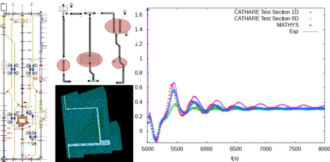
Figure 1: (left) Schematic of the TALL-3D facility with MH, 3D and IHX leg; (center) CATHARE model of the loop and TrioCFD model of the test section; (right) MATHYS prediction for the 3D test
section flowrate during a transition to natural convection. Compared to 0D and 1D standalone CATHARE models, MATHYS is able to capture the timing of the flow peaks: however, additonal
model adjustments will be needed to recover their amplitude.
Located at KTH, the TALL-3D facility [18] (fig. 1) is a LBE experimental loop consisting in three vertical legs: a cooled leg (equipped with a heat exchanger and a pump) and two heated legs:
− the "3D" leg, equipped with a cylindrical test section with a horizontal plate; − the "main heater" (MH) leg, consisting in a straight tube run.
In the 3D leg, the lateral walls of the 3D test section can be heated; in the MH leg, heating is provided by a heated pin instead.
When keeping the heating power equal and constant between the branches, transitions to natural convection exhibit complex behaviour in this experiment: competition between the 3D and MH leg induces large flow oscillations until a new steady-state is reached. These oscillations are strongly affected by 3D phenomena occurring in the 3D leg, where stratification can block the flow until it is broken by an upward jet of cold LBE.
Fig. shows the results of a MATHYS model of TALL-3D coupling a CATHARE model of the entire loop with a TrioCFD model of the 3D section. Feedback from the CFD to the system scale (implemented as a momentum source term in CATHARE) has been shown to strongly affect the results: hence this experiment has been instrumental to validate the domain overlapping methodology used in MATHYS to couple CATHARE and TrioMC/CFD.
4.2 The PLANDTL-DHX experiment
Figure 2: PLANDTL-DHX facility: (left) schematics, (center) coupled TrioMC/TrioCFD model, (right) comparison between simulation (lines) and experiment (dots) of radial and axial in-core temperature profiles. The dissymetry between the subassemblies close to and away from the DHX is
correctly reproduced in the simulations.
The PLANDTL-DHX facility at JAEA [13] is one of the few experiments available to study the effect of inter-wrapper flows on core cooling, as this phenomenon involves multiple
subassemblies and as the high importance of thermal conductivity effects prevents the use of simulant fluid. The PLANDTL-DHX test section consists in a 7-S/A core mockup (a central 37-pin and six 7-pin S/As) immersed in a hot pool mockup consistent with the geometry of JSFR : cooling can be performed either by an IHX or by a DHX in the hot pool : in this last configuration, the role of inter-wrapper flows on core cooling is maximized.
A MATHYS model of the test section coupling a TrioMC model of the 7 S/As with a TrioCFD model of the pool and inter-wrapper region was developed in order to validate the prediction of IWF heat removal under the "DHX-cooled" configuration (fig. 2). Overall, the MATHYS simulation is considered to be in good agreement with the experiment: modeling external heat losses should lead to further improvements.
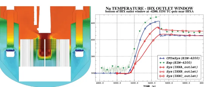
4.3 The PHENIX natural convection test
Figure 3: Coupled models of the PHENIX reactor : (left) MATHYS model using CATHARE/TrioMC /TrioCFD; (right) for the Natural convection test, comparison of a supervisor-based CATHARE /TrioCFD prediction of the IHX outlet temperature (blue) to system-scale (red) and experimental
(green) results.
Reactor data is instrumental to the validation of the multi-scale interactions predicted by MATHYS, which are mostly integral effects. The PHENIX End-Of-Life tests, performed on the 580 MWth reactor after its programmed shutdown in 2009, provide two important reactor tests suitable for integral thermal-hydraulics validation : the natural convection test [8] (a slow transient consisting in an unprotected loss of heat sink followed by a protected loss-of-flow) and the dissymetric test (a trip of one of the reactor's two secondary circuits).
The natural convection-test was one of the first applications of the CATHARE/TrioCFD supervisor-based coupling (cf. (2), §3.1). Analysis highlighted that, while 3D effects in the plena do not strongly affect the overall behavior of the primary circuits, local phenomena (such as the evolution of the IHX outlet jet) affect experimental measurements: these effects are correctly described by the CFD part of the coupled calculation.
A refined MATHYS model of PHENIX including TrioMC (for the core) and TrioCFD (for the IWR, hot pool, IHX primary side, cold pool, and vessel cooling system) is currently under development (fig. 3, left). Validation of this new model on the natural convection and dissymetric tests is ongoing as part of the EU SESAME project [19].
5. Conclusion
A coupling methodology between codes developed at CEA to model SFR thermal-hydraulics at three different scales has been integrated into the MATHYS code. Compared to ad-hoc coupling, this integrated method exhibits, among other advantages, a vastly reduced user effect. Validation of the multi-scale interactions predicted by MATHYS has been started using analytical (PLANDTL-DHX, TALL-3D) and integral (PHENIX) experimental data. Future work will include improvements to the coupling algorithms (convergence improvements, two-phase hydraulic coupling) as well as additional validation on existing and upcoming experiments (PLANDTL-II, THEADES): code-to-code benchmarks, such as those undertaken within the SESAME project, will also provide crucial information.
References
[1] J.-F. Sauvage et al., "Sodium-Cooled Fast Reactors: the ASTRID Plant Project," in ICAPP
2011, Nice, France
[2] MS. Chenaud et al., "Computational thermal-hydraulic schemes for SFR transient studies," in
NURETH-16 (2015).
[3] R. Baviere et al., "Status of CATHARE code for sodium cooled fast reactors," Nucl. Eng. Des. 245, 140-152 (2012)
[4] A. Conti et al., "Numerical Analysis of Core Thermal-Hydraulics for Sodium-cooled Fast Reactors," in NURETH-16 (2015).
[5] V. Barthel et al., "Status of TRIO_U code for sodium cooled fast reactors ," Nucl. Eng. Des. 242, 307-315 (2012).
[6] M. Anderhuber et al., "Simulation Of GR19 Sodium Boiling Experiments With CATHARE2 System Code And Trio_U MC Subchannel Code," in NURETH-16 (2015).
[7] N. Alpy et al., "CATHARE 2 simulations of steady state air/water tests performedin a 1:1 scale SFR sub-assembly mock-up," Annals of Nuclear Energy 83, 283-297 (2015).
[8] D. Pialla et al., "Overview of the system alone and system/CFD coupled calculations of the PHENIX Natural Circulation Test within the THINS project", Nucl. Eng. Des. 290, 78-86 (2015).
[9] V.M. Poplavsky et al., "Experimental investigation of sodium boiling heat exchange in fuel subassembly mockup for perspective fast reactor safety substantiation," Nuclear Energy and
Technology 1, 147-152 (2015).
[10] F. Bertrand et al., "Transient analysis of the ASTRID demonstrator including a gas nitrogen power conversion system with the CATHARE2 code" in NURETH-16 (2015).
[11] JH. Mahaffy, "A Stability Enhancing Two-Step Method for Fluid Flow Calculations", J Comp.
Phys. 46, 329-341 (1982).
[12] H. Ninokata, "Analysis of low-heat-flux sodium boiling test in a 37-pin bundle by the two-fluid model computer code SABENA", Nucl. Eng. Des. 97, 233-246 (1986).
[13] H. Kamide et al., "Investigation of core thermohydraulics in fast reactors - interwrapper flow during natural circulation", J. Nucl. Tech..133, 77-91 (2001).
[14] U. Bieder et al., "CFD calculations of wire wrapped fuel bundles : modelling and validation strategies", in CFD4NRS-3 (2012).
[15] U. Bieder et al., "CFD analysis and experimental validation of mixed convection Sodium flow",
submitted to ICAPP-17 (2017).
[16] PE. Angeli et al., "Large-eddy simulation of thermal striping in WAJECO and PLAJEST experiments with TrioCFD, in NURETH-16 (2015).
[17] D. Guenadou et al., "PLATEAU facility in support to ASTRID and the SFR program: an overview of the first mock-up of the astrid upper plenum, MICAS", in NURETH-16 (2015). [18] D. Grischenko et al., "The TALL-3D facility design and commissioning tests for validation of
coupled STH and CFD codes", Nucl. Eng. Des. 290, 144-153 (2015).