Development of Novel Dynamic Indentation Techniques for
Soft Tissue Applications
by
Asha Balakrishnan
B.S., University of Illinois (1997)
S.M., Massachusetts Institute of Technology (1999)
Submitted to the Department of Mechanical Engineering
in partial fulfillment of the requirements for the degree of
Doctor of Philosophy in Mechanical Engineering
at the
MASSACHUSETTS INSTITUTE OF TECHNOLOGY
September 2007
@ 2007 Massachusetts Insitute of Technology. All rights reserved
The author hereby grants to
to distribute copies
Signature of Author...
Massachusetts Institute of Technology permission to
reproduce and
of this thesis document in whole or in part.
...
..
.-.
...-...
.
. . . . .
(
Department of Mechanical Engineering
/1a
31 August '2007
Certified by ...
...Simona Socrate Assistant Pofessor of Mechanical Engineering Thesis Supervisor
A ccepted by ... ... #...
Lallit Anand
HUSETTS INSTITUTE. Chairperson, Department Committee on Graduate Students TEOHNOLOGY
Akk
0
3 2008
ACN
ARCHBVE
MASAC
OfDevelopment of Novel Dynamic Indentation Techniques for Soft Tissue
Applications
by
Asha Balakrishnan
Submitted to the Department of Mechanical Engineering on 31 August 2007, in partial fulfillment of the
requirements for the degree of
Doctor of Philosophy in Mechanical Engineering
Abstract
Realistic material models to simulate the behavior of brain tissue at large deformations and high strain rates are necessary when designing equipment to protect against ballistic impacts. Acquiring experimental data for brain tissue response is critical to developing appropriate mod-els. Current in vivo and in situ procedures for testing the material behavior of soft tissues are dominated by indentation techniques. The major challenge for this testing configuration is in finding a unique solution to the "inverse problem" i.e., obtaining material properties that are uniquely defined by the indentation force-displacement response. Much of the information related to the interplay between shear and bulk compliance in the deformation field beneath the indenter is lost when capturing the single force-displacement output.
To address this challenge, we propose a material testing technique that follows the well-proven path of conventional indentation methods, but also enriches the signal by acquiring displacement data for an offset, passive surface tracking sensor. We present the results of a finite element (FE) study to demonstrate that the addition of a secondary sensor can help to discern between materials with varying degrees of compressibility. To this end, a large displacement in vivo dynamic indentation surface tracking (DIST) tool was designed and manufactured. This tool incorporates the secondary sensor concept to measure the force-displacement response of brain tissue at strain rates up to 1000%/s. The technique is applied in vitro to measure the response of porcine brain tissue. To select an appropriate constitutive framework for porcine brain tissue in vitro, uniaxial compression tests measuring the corresponding lateral stretch response are performed. A three-dimensional large deformation constitutive model for brain tissue is developed. The model accounts for the observed features of the material response including non-linearity, conditioning, hysteresis, and strain-rate dependence. The model is incorporated into an FE simulation of the brain indentation tests performed with the DIST tool. The effectiveness of the DIST as a material-testing tool is assessed.
Thesis Supervisor: Simona Socrate
Contents
1 Introduction
1.1 Thesis objective and outline . . . .
2 Background and Motivation
2.1 Traumatic brain injury . . . .
2.2 Surgical simulation . . . .
2.3 Anatomy of the human head . . . .
2.4 Literature review of brain tissue properties . .
2.4.1 Testing brain behavior in shear . . . . .
2.4.2 Compression testing . . . .
2.4.3 In vitro vs. in vivo behavior . . . .
2.4.4 Effect of region and post-mortem time
3 In Vivo Tool Designs
3.1 Literature review of in vivo measurement tools
3.2 Proposed designs . . . .
3.2.1 In vivo retractor tester . . . .
3.2.2 In vivo spring tester . . . .
3.2.3 In vivo dynamic indentation tool . . . .
3.3 Mounting configurations . . . .
3.3.1 MRI frame configuration . . . .
3.3.2 Benchtop frame configuration . . . .
3.4 Tool validation and calibration . . . .
13 13 16 17 18 19 20 21 22 23 23 25 25 26 26 29 31 35 35 38 40 . . . . . . . .
3.5 Tool design conclusions . . . 43
4 Secondary Sensor Design 44 4.1 Literature review of indentation . . . 46
4.2 Novel design addition . . . 48
4.3 Methods ... ... ... ... 51
4.4 Simulations results of secondary sensor additions . . . . 55
4.4.1 Case I: Linear elastic response . . . . 55
4.4.2 Case II: Hyperelastic response . . . . 56
4.4.3 Case III: Poroelastic vs. Viscoelastic Response . . . . 56
4.5 Secondary sensor discussion . . . 57
5 Validation of Secondary Sensor Concept 61 5.1 Design of validation tools . . . . 61
5.2 Validation on stiff materials . . . 62
5.2.1 Spring sensor . . . . 62
5.2.2 Aquaflex . . . 63
5.3 Validation on soft tissue simulant . . . 66
5.3.1 Unconfined compression . . . 67
5.3.2 Indentation experiments . . . 71
5.3.3 Indentation simulation . . . 76
5.4 Conclusions . . . 80
6 In Vitro Porcine Brain Tissue Testing 81 6.1 Methods of in vitro testing . . . 81
6.1.1 Compression experiments . . . 82
6.1.2 Indentation experiments . . . 85
6.1.3 Indentation with secondary sensor experiments . . . 88
6.2 In vitro results . . . 89
6.2.1 Results: Uniaxial unconfined compression . . . 89
6.2.3 Results: Indentation with Secondary Sensor Addition . . . . 98
6.3 In vitro brain testing conclusions . . . 101
7 Brain Tissue Material Model 105 7.1 Literature review of existing FE models . . . 105
7.2 Three-dimensional constitutive model . . . 106
7.2.1 Pre-conditioned response (primary model) . . . 106
7.2.2 Conditioning Response . . . 113
7.2.3 Model Fit: Uniaxial compression using pre-conditioned network . . . 117
7.2.4 Model Fit: Uniaxial compression response with both pre-conditioned and conditioning networks . . . 122
7.2.5 Model Fit: Indentation with secondary sensor experiments . . . 129
7.2.6 A secondary sensor placement sensitivity study . . . 135
7.3 Three-dimensional model conclusions . . . 137
8 Conclusions and Future Work 138 8.1 Concluding remarks . . . 138
List of Figures
2-1 Basic anatomy of brain tissue . . . . 20
3-1 Image of normal use of a retractor on a porcine brain . . . . 27
3-2 Retractor assembly designed to measure in vivo static forces applied to the brain
during neurosurgery . . . . 28
3-3 Design details of in vivo spring-loaded material testing device . . . . 30
3-4 Portable spring-loaded mechanical tester shown with data acquisition system . . 30
3-5 Tool capabilities given by the frequency of oscillation versus the depth of
inden-tation travelling in air . . . 32
3-6 A cross-sectional view of the in vivo dynamic indentation tool . . . . 33 3-7 Schematic of data acquisition and motion control architecture for indentation
device . . . 36
3-8 Detailed drawings of frame footprint and the ranges of motion in the linear axes 37 3-9 Frame for mounting tool in the laboratory . . . 38 3-10 Contour plot of the frame deflection under static loading . . . . 39 3-11 Model used to assess the stiffness of the mechanical system . . . 40 3-12 Results of a validation study comparing the force output on the ElectroForce
machine and the dynamic indentation tool . . . 41
3-13 Filtered force signal from the in vivo tool compared with the force signal from
the ElectroForce Machine . . . 42 4-1 Dynamic indentation surface tracking (DIST) tool configuration . . . 50 4-2 Three-dimensional finite element model . . . 51
4-3 Imposed displacement history for indenter and for secondary sensor . . . . 52
4-4 Typical simulation output based on input conditions . . . . 53
4-5 Linear elastic results . . . . 55
4-6 Hyperelastic simulation results . . . . 57
4-7 Poroelastic and viscoelastic simulation results . . . . 58
4-8 Parametric study to determine optimal spring stiffness . . . . 59
5-1 Experimental setup for validating secondary sensors on ElectroForce Machine: (a) Isometric view (b) Top view showing discrete sensor position locations . . . 62
5-2 Finite element contour plot of vertical displacement of secondary sensor mounting bracket . . . . 63
5-3 Image and description of spring-loaded sensor integrated into ElectroForce ap-paratus . . . .
64
5-4 Force-displacement response for indentation testing to different depths on Aquaflex 65 5-5 Force history for indenter (left axis) and displacement history (right axis) for secondary sensor . . . 65
5-6 Stress-strain response for RTV and brain tissue tested in uniaxial unconfined com pression . . . 66
5-7 Strain history for uniaxial unconfined compression experiments for RTV 6166 specim ens . . . 68
5-8 Stress-strain behavior for RTV 6166 (50:50) tested in uniaxial unconfined com-pression . . . .
69
5-9 Stress relaxation response for RTV 6166 (50:50) tested to 50% strain in uncon-fined compression at 100%/s loading rate . . . 69
5-10 Lateral vs. axial stretch response for RTV 6166 50:50 tested to 50% nominal strain 70 5-11 Rheometer data for RTV 6166 at small strains (1-10%) . . . . 72
5-12 Indentation apparatus with secondary sensor (without spring) . . . 72
5-13 Depth and frequency dependence studies of the secondary sensor testing for in-dentation testing of RTV 6166 (50:50) . . . 74
5-14 Secondary sensor location study . . . 75
5-16 Three-dimensional simulation of indentation with secondary sensor experiment . 77 5-17 Experimental and model results for pure indentation tests with and without the
skin ... ... 78
5-18 A contour plot of the indenter at the fully extended position . . . 79 5-19 Comparison between the experimental results, and simulated indenter force and
secondary sensor displacement response on RTV 6166 (50:50) . . . 79
6-1 Brain Tissue: (a) Freshly cut square brain tissue specimen, (b) Brain tissue
specimen prior to loading in ElectroForce machine . . . 83
6-2 Bose ElectroForce 3200 dynamic mechanical tester with video extensometer . . . 84
6-3 Video extensometer data acquisition . . . 84
6-4 Strain (true) history for in vitro porcine brain tissue specimens testing in uniaxial com pression . . . 85
6-5 Indentation on a porcine brain hemisphere using a 12.5mm-diameter spherical
indenter . . . 86
6-6 Displacement history for in vitro indentation experiments on a hemisphere of
porcine brain tissue . . . 87
6-7 Setup of indenter and secondary sensing device testing brain tissue on
Electro-Force M achine . . . 88
6-8 Load-Unload mean with standard deviations for nine specimen tested in uniaxial
unconfined compression . . . 90
6-9 Stress relaxation mean and standard deviation for 9 samples of porcine brain
tissue tested in uniaxial compression . . . 91
6-10 Resulting stress history from strain history given in Figure 6-4 on a representative
specimen of brain tissue . . . 93
6-11 Representative stress-strain result of a specimen tested in uniaxial compression . 94
6-12 Stress relaxation results from a representative sample tested in uniaxial compression 95 6-13 Effect of porcine age on material response: comparison between 3 months and 18
m onths of age . . . 97 6-14 Lateral vs. axial stretch for a representative sample of brain tissue testing in
6-15 Volumetric stretch history for a representative sample of brain tissue tested in
unconfined compression . . . . 99
6-16 Force-displacement response of brain tissue tested in indentation . . . 100
6-17 Indentation force history response based on strain history input shown in figure 6-6 ... ... 101
6-18 The force and secondary sensor response to changing the location of indentation on the same brain specimen . . . 102
6-19 Effect of increasing depth on indenter force and secondary sensor results . . . 103
7-1 Proposed rheological model to describe the behavior of brain tissue . . . 107
7-2 Large strain kinematics for rheological model . . . 108
7-3 The 8-chain fiber network unit cell and principal stretches under deformation . . 110
7-4 Conditioning response network to be added to pre-conditioned network . . . 114
7-5 Large frame kinematic network for conditioning network . . . 114
7-6 Complete three-dimensional model capturing both the pre-conditioned and con-ditioning responses of the material . . . 118
7-7 Proposed three-dimensional consititutive model with material properties . . . 119
7-8 Experimental data with model fit for uniaxial compression response of brain tissue at a 100%/s loading rate . . . 121
7-9 Experimental data with model fit for uniaxial compression response of brain tissue at a 10%/s loading rate . . . 122
7-10 Experimental data with model fit for uniaxial compression response of brain tissue at a 1%/s loading rate . . . 123
7-11 Experimental data with model fit for uniaxial compression stress relaxation re-sponse of brain tissue . . . 123
7-12 Experimental data with model fit for the lateral strain response of brain tissue compression testing . . . 124
7-13 The effect of varying the bulk modulus on the stress history and lateral strain history of the simulation . . . 125
7-14 A single load-unload cycle indicating the effect of changing the bulk modulus on the true stress history and lateral strain history of the similation results . . . 126
7-15 Model fit to experiments using the conditioning network model . . . 127 7-16 The contribution of the additional network to the stress relaxation response . . .127 7-17 The model fit to the experimental load-unload response using both the
pre-conditioned and conditioning networks in parallel . . . 128
7-18 The model fit of the experimental stress relaxation response to both the
pre-conditioned and conditioning networks in parallel . . . 128
7-19 The model fit to the experimental lateral strain history using both the
pre-conditioned and conditioning networks in parallel . . . 129
7-20 Experimental setup of brain indentation test with secondary sensor . . . 130 7-21 FE simulation of indentation experiment with secondary sensor . . . 131 7-22 The model-predicted indenter force and secondary displacement response to the
experim ental results . . . 132
7-23 Contour plot of the displacement of the indenter and secondary in the loading
direction . . . 133 7-24 The effect of varying the bulk modulus on the indenter force and secondary sensor
displacem ent . . . 134
7-25 The effect of changing the bulk modulus on the resulting force and secondary
sensor displacement in the simulation compared with the experimental response 135
7-26 The sensitivity of the bulk respose of the material as indicated by the distance
List of Tables
2.1 Literature review of brain tissue testing . . . 22
3.1 Specifications of in vivo spring-loaded tool . . . 29
3.2 Specifications of dynamic indentation surface tracking (DIST) tool design . . . . 33
3.3 Dynam ics of tool . . . 40
5.1 Estimated RTV 6166 (50:50) material properties . . . 71
6.1 Comprehensive description of in vitro compression specimens . . . 92
7.1 Values for the material parameters of the proposed three-dimensional model . .121
Acknowledgements
We are not able to accomplish anything in a vacuum; without the help, support or guidance of others. I have been fortunate enough to have many people help me get here. To my labmates and colleagues: Petch, Tim, Bruce, Mike, Amy, Kristin, Anastassia and Una for always being there to listen and for keeping the lab environment lively and enriched. I have learned so much from them. I am particularly grateful to Thibault, who put an unbelievable amount of effort into helping me finish the work towards the end. I want to thank and acknowledge the help of Pierce in the Mechanics lab for always being available to lend a hand, and of Peter in the Central Machine Shop at MIT for teaching me the essence of design for manufacturing. To my colleagues at the Brigham and Women's hospital, Dan Kacher and Florin Talos, for teaching me about the medical aspects of this work, and providing a venue for the experiments to be carried out. Professor Alex Slocum was my enabler; he convinced me and paved the way for me to come back to MIT for a PhD, he encouraged and inspired me to keep going, and he taught me many lessons in not only engineering principles, but life principles that guide me today.
My advisor, Professor Simona Socrate, is a person who cares for students far more than any
professor I have met. She spent many hours teaching me and assisting me in this work. For all her help with my work and life outside work, I am truly thankful. To my friends and family, for showing their support in countless ways. To my parents, for encouraging me to keep going, and for their patience and unwavering support throughout this process. My father inspired me to be an engineer many years back and this thesis is dedicated to him for sowing the seed of curiosity in me at an early age. To Manish, who has stood by me through many of this year's trials and tribulations. His support and encouragement towards the end really helped me complete the PhD. At a particularly difficult time in my life, I feel blessed to have had so many people came together to help me. And to Sri Sathya Sai Baba, my spiritual teacher, who has taught me and continues to teach me the values by which I live.
Chapter 1
Introduction
1.1
Thesis objective and outline
The brain is a complex structure that exhibits both solid and fluid -like behaviors at the macroscopic scale. Characterizing the material behavior of brain tissue remains challenging because the requisite model must encompass the tissue response for relatively large deformations and frequency ranges. This nonlinear characterization is particularly pertinent for brain injuries sustained by dynamic loads in which criteria for damage and injury thresholds for the brain are of great interest. The focus of this thesis in briefly described in the following outline.
I. Thesis background and motivation
Chapter 2 develops the premise and motivation for this work. A literature review of the
mechanical response and properties of brain tissue is presented. Characterizations of the
nonlinear hyper- viscoelastic nature of this material will be included.
II.
Development a portable in vivo dynamic indentation tool to measureprop-erties of soft tissues
In Chapter 3, the development of several in vivo tools are discussed. In the initial phases of this project, a tool was developed to perform in vivo force-displacement experiments adapting procedures consistent with neurosurgery. To assess the high rate response of soft tissues, an in vivo spring-loaded one-shot tool was also developed. Lastly, an oscillating dynamic indentation tool capable of large deformations and high strain rates was developed. Although the other tools were designed and developed, the focus of subsequent work was on the portable in vivo
dynamic indentation tool. Further development and troubleshooting of the other tools will be suggested future work.
III. Adaptation of designed tool with additional sensors to improve the
char-acterization of material behavior
Chapter 4 describes the proof-of-concept of incorporating additional surface tracking sensors to characterize the behavior of soft tissues when the material cannot be removed from their original configuration (i.e. in vivo). Using three-dimensional finite element simulations, these additional sensors are shown to enrich the response by elucidating trade-offs between the bulk and shear responses.
IV. Validation of tool design with additional sensors on stable tissue-like
simu-lants
In Chapter 5, the validation of the in vivo dynamic indentation tester is presented. After the modifications necessary for the addition of the secondary sensors are made, the concept presented in Chapter 3 is validated on stable tissue-like silicon gel simulants. The sensor characteristics (location, range of motion, stiffness, frequency response) are demonstrated and optimized for an in vivo testing configurations.
V. In vitro experimentation of large deformation mechanical response of porcine brain tissue
Chapter 6 describes efforts undertaken to gain insight into the mechanical response of porcine brain tissue. Because in vivo studies are costly and challenging to arrange, initial investigations to understand the specific features of the in vitro mechanical response to uniax-ial unconfined compression and indentation are performed. Indentation experiments using the secondary sensor are also conducted. The results of these studies are presented.
VI. Determination of an appropriate constitutive model of porcine brain tissue
In this chapter, the constitutive framework for the mechanical behavior of in vitro porcine brain tissue is presented. Features of the experimental response such as nonlinearity, hysteresis, conditioning, and strain rate effects are considered when developing this model. A model, noted as the pre-conditioned model, that captures the nonlinearity, time dependence and strain rate dependence is first presented. Another model to capture the conditioning response of the material is placed in parallel with the first model. The model fit to the experimental unconfined
compression and indentation results is presented and discussed. The indentation experiment with secondary sensor conducted in Chapter 6 is simulated. The displacement of the secondary sensor is predicted and compared with the experimental results.
Chapter 2
Background and Motivation
Understanding the mechanical behavior of brain tissue is of great interest for the purpose of injury simulation, surgical simulation, and medical diagnosis. Obtaining these properties is a significant challenge due to the mechanical and geometric nonlinearities, multi-constituent het-erogeneity, viscoelastic nature, and poorly defined boundary conditions of soft tissues. Phys-ically realistic models of brain tissue are used to simulate the effects of crash and projectile impacts upon body armor. New technologies for armor are being developed, but the mechani-cal behavior of brain tissue under high rate high deformation loading must be better understood. Additionally, surgical simulation and image-guided surgery strive to enhance the surgeon's ca-pability to utilize advances in medical imaging and reduce the degree to which the surgery is invasive. During the last decade, physically realistic models for surgical planning have gained more favor and created a need for determining material properties of tissue.
Improvements in the understanding of soft tissue material behavior is undergoing rapid evolution; however major problems still remain. Due to cell death and lack of perfusion, excised tissue (in vitro) behaves differently from living tissue (in vivo) [26] [49]. Limited access to living tissue, particularly soft tissue, catalyzes the need for accurate correlation between in vivo testing and in vitro testing. This also suggests that in vivo studies of soft tissues must be conducted;
2.1
Traumatic brain injury
Traumatic brain injury (TBI) is a of the leading causes of death and disability among young people in the developed world [85]. In the United States, TBI is responsible for 500,000 people being hospitalized each year with 2 million reported cases worldwide per year [86]. In the
western hemisphere, TBI represents 15% of all fatalities and disabilities [61]. According to
Finfer et al., this proportion will increase to 20% by 2020 and TBI will become the third
leading cause of whole-population death and disability [22]. Head injuries largely result from
falls, sporting accidents, and automobile accidents. In combat/blast-related situations, injuries most often occur due to a blast wave from detonated improvised explosive devices (IED) [77]. Such events are not well-documented or understood, and while ballistic helmets offer protection, injuries to the skull and brain matter still occur.
Mechanisms that cause TBI are largely unknown; investigations necessary to understanding links between physiological damage, physical damage and neurological impairments are ongoing. Taylor et al. [77] asserts that distinct cell damage mechanisms can occur when the cells are subjected to isotropic stress (i.e., pressure) and/or shearing stress. In other words, internal cell damage occurs when tensile and compressive pressures impose a volumetric change in the cell. The second mechanism is related to the shearing stress that causes the tearing of cellular membranes in neurons.
Gurdjian et al. [28] pioneered the field of head injury biomechanics by creating tolerance curves of acceleration and intracranial pressure. Through this work, the Wayne State University Tolerance Curve (WSUTC) was proposed and the Head Injury Criteria (HIC) was developed. Measures taken to improve protective head gear are typically evaluated against a measurement of HIC. HIC is said to be proportional to the intracranial pressure, shear stress, and skull von Mises stress [68]. However, this method has been criticized due to its limited ability to predict the probability of brain injury [87]. It is suggested that the specific deformation of brain tissue and the relative motion of the brain with respect to the skull would be a better means
of assessing head protection [1]. In order to better understand brain injury biomechanics,
mathematical models are employed. Over the past few years, several three-dimensional FE models of the human head have been extensively used to understand and to predict head
response as an injury indicator for diffuse axonal injury (DAI) [68][91]. Zhang et al. used head collision data to validate the FE model. Shear stresses around the brain stem were discovered to be a predictor for concussions. Through this work, a new brain injury tolerance level was suggested [89]. Klevien et al. developed a detailed and parameterized FE model of the human head, and used it to evaluate the effects of head size, brain size and impact directions [37]. Brain injuries are clearly associated with the large strains that result when shearing or tearing of biological tissue occurs. A major limitation that impedes the progress of FE modeling for dynamic applications is the lack of data on brain tissue behavior tested at large strains and high strain rates. To improve FE modeling of head injury and to develop effective brain injury prevention systems, better knowledge of the complex material properties and interface conditions of the human head, as well as more experimental data relating to brain motion and large strain deformation are needed.
2.2
Surgical simulation
Modeling the deformation of human organs for surgical simulation systems is a challenging undertaking. Not only is very little known about the physical properties of general human tissue but in addition, most conventional modeling techniques are not applicable because of the timing requirements of simulation systems. In the fields of elasticity and related modeling paradigms, the main interest has been the development of accurate mathematical models [11]. There has been much effort spent towards the development of image-guided surgical techniques in the area of minimally invasive neurosurgery over the past ten years. A major challenge in the field of neurosurgery is minimizing the removal of healthy tissue and maintaining the integrity of critical anatomical structures while resecting a tumor [83]. Algorithms to create enhanced visualizations of the tumor and critical brain structures by aligning high-resolution preoperative images (MRI, CT) with intraoperative images of the brain during surgery are being developed and refined to improve the arena of neurosurgical simulation.
Nimsky et al. observed that the cortical surface of the tumor margin was displaced up to 24mm in 2/3 of the cases studied [57]. These large displacements clearly exceed the accuracy desired for image-guided surgical procedures. Nabavi et al. [54] demonstrated that shifts of
the tumor margins and cortical surfaces occur over time during the resection procedure. In order to observe these changes in real-time, intraoperative imaging techniques are employed in the form of either ultrasound (US), magnetic resonance (MR), computed tomography (CT) or stereoscopic microscopy [42]. These studies have made it clear that there is value in using biomechanical models to improve the utilization of intraoperative data [16][18]. Warfield et
al. [83] present an analysis of inferring volumetric brain deformation through biomechanical
simulations with boundary conditions established by matching the brain surface with the tumor margins. Predicted volumetric shifts of the brain are based on the form and accuracy of the material model applied to the simulation. Clearly, the advancement of the work in the field of surgical simulation is highly dependant on the accuracy of the biomechanical simulations that are predicting deformations. In the specific case of neurosurgery, accurate brain tissue properties are critical to improving FE models and simulations.
2.3
Anatomy of the human head
To aid in the understanding of traumatic brain injuries and surgical simulation, it is useful to present a basic anatomical and physiological background of the human head. The head consists of the facial portion on the anterior side and cranial skull that covers the brain on the posterior side. Between the scalp and the skull, there is a loose connective-tissue layer and a fibrous membrane surrounding the bones. Moving inwards, three membranes encase the brain: the dura mater, the arachnoid, and the pia mater. These membranes are collectively called the meninges, and are separated from each other by subdural and subarachnoidal spaces, respectively, and are filled with cerebrospinal fluid (CSF). This fluid is understood to play a role in absorbing impact to the head, and the presence of this fluid suggests that material behavior is partially governed by the permeability of the material. The water content of brain tissue is nearly 80%, and therefore the brain is often times modeled as nearly incompressible [73].
The brain consists largely of a combination of white matter and gray matter. Gray matter is primarily composed of nerve cell bodies (neurons) and glial cells. White matter is composed of myelinated nerve cells (axons). Blood vessels intertwine throughout the tissue. The brain is structurally separated in several parts. The most important ones are the cerebrum, the
Limbic System
Hippocampus Crebellum
Medulla Parlhippocmpal
oblongata gyrus
Figure 2-1: Basic anatomy of brain tissue
cerebellum, and the brain stem which consists of midbrain, pons and medulla oblongata. The cerebrum is divided into four different areas: the frontal lobe, the parietal lobe, the occipital
lobe, and the temporal lobe as shown in Figure 2-1. Gray matter is often assumed to be
isotropic in nature. White matter is often considered anisotropic as the myelinated axons of white matter demonstrate prominent directional differences [66]. However, the approximation of isotropy existing throughout the brain tissue is adopted by many investigators [17] [20] [49] [70], especially when treating the white matter and gray matter as a mixed homogenous material.
2.4
Literature review of brain tissue properties
The mechanical response of brain tissue has been investigated for the past several years. Investi-gators have attempted to understand the mechanical response of brain tissue through variations and combinations of four different experimental parameters: loading configurations (compres-sion, shear, indentation, tension); loading histories (cyclic, stress relaxation, creep); states (in vitro, in situ, in vivo); and testing regimes (high strain/low strain rate or low strain/high strain rate). Each test method is adept at revealing certain information about the material behavior
of brain matter, but is not capable of fully characterizing brain tissue response. In the following section, a comprehensive literature review of experiments on brain tissue materials is discussed. Table 2.1 provides and overview of brain property experiments and their proposed constitutive models.
2.4.1 Testing brain behavior in shear
Much of the in vitro brain tissue work has been performed in the shear loading configuration [2] [6][10] [65] [66] [75] [78]. Reported properties of brain tissue vary more than an order of mag-nitude. These differences may be attributed to testing at various post mortem times, testing different donor species, anisotropy of the tissue, and the non-homogenous nature of the brain. Animal tissue is often used as a substitute for human brain tissue. It is more easily available and can be tested at shorter post mortem times. Porcine and bovine tissue are well accepted animal models for human brain tissue [17] [56].
Galford and McElhaney performed a viscoelasticity study of the scalp, brain, and dura to understand the time-dependence of the various major components of the head [24]. Fallstein and Hulce performed one of the first experiments to study mechanical phenomena associated with impact to the head [21]. Nicolle et al. [56] performed a series of in vitro experiments over a large frequency range. This work compared human brain tissue to that of porcine tissue, and concluded that there exists no significant difference between the two, thereby establishing porcine brain tissue as an acceptable model for human brain tissue. In addition, this group
performed high frequency rheometry experiments in frequencies ranging from
0.1Hz
to 10000Hz.The high frequency experiments were performed at low strain, and conversely the low frequency was performed at high strain. Typical frequencies below 1000Hz are associated with traffic accidents [3] [65]. For non-penetrating ballistic impacts, frequencies over 1000Hz are assumed
[8][30]. Nicolle et al. [56] also observed the influence of different test parameters: degeneration
Table 2.1: Literature review of brain tissue testing
Post-mortem Author Mode Strain level Strain rate Sample size Species Time (h) Model Estes and McElhaney UCC 0.37 0.08 -40 1/s d = 12.6mm Human 6-10
(mixed h = 10.9mm matter)
Four Parameter Shuck and Advani 0S 1.30% 5 -350Hz d = 12.6mm Human few Viscoelastic
(white and gray h = 3.1 -12.6mm matter)
Mendis et at. based on Estes and McElhaney (1970) QLV
Power law based on standard linear Donnelly and Medige Shear 100% 0-901/s d = 12.4 - 19mm Human 48 solid
(mixed h = 5.3 - 26.4mm matter) 0.64e-5 -0.64
Miller and Chinzei UCC 0.35 1/s d = 30mm Porcine 12 QLV
(mixed
h = 13mm matter) Thibault and Margulies 0S 2.5 -5% 20 -200Hz d = 10 - 12mm Porcine 3
Front
h = 1 -2mm cerebrum
Multiple hereditary Darvish and Crandall 0S 10% 0.5 - 2000Hz d = 15 -20mm Bovine 24 integral QLV
(mixed h = 4.8mm matter)
Differential Bilston et al. 0S 0.10% 0.01 - 10Hz d = 20mm Bovine 8 form
Corpus h = 2mm callosum Shear rise time =
Prange and Margulies Relaxation 5-100% 0.05s I = 10mm, w = 5mm Porcine 5 QLV (white and gray h = 1mm matter) Human 3 (gray) 0.64e-2 - 0.64
Miller and Chinzei Tension 1.3 1/s d = 30mm Porcine 12 QLV
(mixed
h = 10mm matter)
Differential Brands OS, TTS 1% 1 -1000Hz d = 12mm Porcine 4 form
(mixed
h = 1-2mm matter)
Stress relaxation Gefen and Margulies Indentation depth = 4mm 1mm/s -3mm/s N/A Porcine function
relaxation in vivo / in
situ Nicolle et al. OS
OS = Oscillatory shear
UCC = Unconfined compression
2.4.2 Compression testing
Galford and McElhaney performed a series of creep and stress relaxation tests in compression of monkey and human tissue [24]. This study was the basis for much of the subsequent work on brain tissue. Miller et al. has performed unconfined compression and tension studies in vitro [49][50]. The compression and tension tests were done at strain rates between le-5 s-1 to leO
s-1. In compression, porcine tissue samples were tested in the large strain regime (Emax =0.64) in loading. Unloading data was not given, however nonlinearities in the large strain response
were observed. Incompressibility of the material is often assumed in models of brain tissue [20][45][64]. Cheng and Bilston investigated the behavior of brain tissue white matter under
a stress relaxation loading input at three different rates [13]. To understand cerebrospinal
fluid flow in the brain, they determined the permeability of the white matter and modeled the response of brain tissue white matter with a poroviscoelastic model.
2.4.3 In vitro vs. in vivo behavior
In the past few decades, some studies have conducted to understand differences between living
and non-living tissue [26][51][50][56]. In vitro testing is the most accessible method to
deter-mining the material response of tissues; however research suggests that there are significant differences between in vitro and in vivo behavior. Gefen and Margulies [26] showed that there is a definite preconditioning effect between the first and fifth/sixth cycles of testing. In addition, it was found that there was a significant difference between the long-term shear modulus of in vivo and in situ stress relaxation curves, which suggest that at longer time constants in situ or in vitro tests do not compare well with the behavior of living tissue. Miller also reported compression tests performed in vitro resulted in a 30% decreased stiffness compared to inden-tation tests performed in vivo [51]. Neither of these studies show the unloading behavior of the material. Both perform stress relaxation tests; however, hysteresis effects of the unloading phase were not captured.
2.4.4 Effect of region and post-mortem time
A few studies on the differences between white matter and grey matter material properties have
been conducted. Prange and Margulies [66] showed that the difference in mechanical response between white matter from the corpus callosum and grey matter from the thalamus region may reach up to 30%. In the same study, human samples obtained from temporal lobectomies performed on epileptic patients, were on average 29% stiffer than porcine samples. Moreover, they reported that differences attributed to anisotropy of grey matter and white matter were up to 10% and up to 50%, respectively. In this work, the effect of white and grey matter are not separated as the investigation aims to understand the global response to the tissue as a whole.
The differences in the aforementioned researchers' work are significant. Some of these dif-ferences may be attributed to variations post-mortem time of assessing the tissue. Metz et al. [46] have reported a 30-70% decrease in tissue response to the inflation of a balloon catheter between live samples and samples taken 3/4 hour post-mortem. McElhaney et al. [43] have reported no significant changes in sample properties up to 15 hours post-mortem, and Nicolle
et al. [56] have reported only a 6% increase of shear modulus between samples measured at
24 and 48 hours post-mortem. Many authors suggest that the tissue would degenerate with increasing post-mortem time due to various reasons (e.g., autolytic processes, completion of rigor mortis, osmotic swelling, etc.). Due to interspecies and protocol testing differences, there are discrepancies in the literature regarding amplitude and frequency-dependence of the shear moduli in the linear field.
Most of the work performed on brain tissue has been conducted in the linear viscoelastic regime at high frequencies or at larger deformations at low strain rates. More testing needs to be conducted in the regime of large deformation at high strain rates. The work performed in this thesis aims to address this void in the literature. In addition, much of the work previously done on brain tissue is tested only in one mode of deformation. Often times in the case of unconfined compression only the loading data is recorded and the unloading data is ignored, thus losing valuable information as to the time dependent characteristics of the material. While it is widely accepted that brain tissue exhibits strain-rate dependence, efforts to quantify this dependence need to be investigated. This is especially the case if the characterization at the relatively lower strain rates is to be extrapolated into strain rate regimes consistent with those experienced in traumatic brain injury.
Chapter 3
In Vivo Tool Designs
In this section the design of several in vivo tools are discussed. The in vivo large displacement dynamic indentation tool is the only tool that has undergone full development. The control ar-chitecture and tool validation are also presented. Existing in vivo tools are limited to capturing the material response at small and high strain rates, or large strains at quasistatic loading rates. The tools presented in this section are designed to address and fill the gap in the literature for in vivo measurement.
3.1
Literature review of in vivo measurement tools
A number of small, portable in vivo tools have been proposed in the literature [34] [55][63] [80].
Ottensmeyer designed the TeMPeST 1-D, a 12mm-diameter minimally invasive instrument to measure the compliance of solid organ tissues [63]. A 5mm-diameter circular punch is driven to vibrate by a voice coil motor to displacements of ±0.5mm while in contact with the tissue. The tool simultaneously records the applied load and relative displacement. When in contact with organ tissues, the open loop bandwidth is approximately 80Hz and forces up to 300mN can be exerted. The tool has been used in in vivo studies to measure the mechanical response of porcine liver and spleen. The TeMPeST 1-D captures the small strain, relatively high frequency response of the tested material. To determine the compliance of the material, a closed form solution for the indentation of a circular punch on a semi-infinite body is employed. Kalanovic
travels up to a frequency of 20Hz [34]. The ROSA-2 device has a 6mm circular contact that rotates relative to a concentric ring fixed to the tissue with a pin array or tissue sealant. The torque on the tissue is exerted by a galvanometer. This device was validated on a gel simulant and preliminary results for soft tissues were presented. Valtorta and Mazza designed an in vivo torsional resonator device to perform dynamic shear testing [80]. By controlling the vibration aplitude, shear strains of less than 0.2% are induced in the tissue so that the material response is within the linear elastic regime. The complex shear modulus is characterized in the range of 1 to 10kHz. The material response due to motions induced by this tester are considered in the linear viscoelastic regime. Nava et al. designed an in vivo aspiration device in which a cannula with a 10mm diameter hole is placed in contact with the tissue and vacuum is applied. The internal pressure in the tube is maintained according to the desired pressure profile [55]. As a result, the tissue lifts into the tube and the corresponding displacement profile is captured by digital images taken from the side view. Using a linear viscoelastic model, the experiment is simulated and the material properties are obtained through solving the inverse problem (i.e., matching the simulation response to the experimental response by adjusting the material parameters of the simulation). While these tools offer capabilities in measuring the material response in the linear viscoelastic regime, they do not address the need to understand the large deformation, high strain rate material response of soft tissue in vivo.
3.2
Proposed designs
3.2.1 In vivo retractor tester
A key challenge in the surgical removal of brain tissue tumors is to ensure the removal of
only tumor tissue, while keeping healthy tissue intact. To achieve this goal, improvements in the areas of surgical visualization and surgical navigation have been made within the past decade [33]. Additionally, the development of intraoperative magnetic resonance image-guided surgery has improved the procedure for tumor resections, but has at the same time highlighted the problem. of brain shift (brain shape deformation) that occurs during surgery [54]. During neurosurgery, a brain retractor is often used to constrain certain areas of the brain (see Figure
Figure 3-1: Image of normal use of a retractor on a porcine brain
measurements. Through these measurements, in vivo material properties can be inferred. To test the forces applied to the brain by the retractor during neurosurgery, we equipped the brain retractor with a force sensing device, calibrated the device to measure the load at the end of the retractor and built the apparatus. The surgery will occur on a porcine brain, a well-accepted animal model to simulate human brain tissue [26][51]. To understand the location of the retractor relative to the other structures in the brain, we planned to use Magnetic Resonance Imaging (MRI). MRI of the brain will allow us to capture the entire volume of the brain as well as visualize the deformation of the volume due to the positional changes of the retractor. A resulting design specification was that all components of the device had to be MRI-compatible and could not contain ferrous materials. The retractor had to be kept as thin as possible, or at least as thin as existing retractors, and had to fit between the two hemispheres of the brain without damaging any surrounding tissue. This constraint was particularly challenging as most force sensors are attached at the point where the force that is to be measured, and traditional force sensors do not offer such thin profiles. To address these constraints, we designed a retractor tester that measures the force applied to the tissue at a location away from the contact point (see Figure 3-2). The retractor contacts the brain tissue with a cylindrical disk that sits at the end of a telescoping set of hollow copper tubes. This assembly was to be placed in between the left and right hemisphere of the brain. Once the placement (depth and lateral locations) of the
173 mm
E Threaded nut inside
S Force Ampllleation threaded housing to
(cretes 2:1 ratio) aply displacement
Famce Senwor
F
Figure 3-2: Retractor assembly designed to measure in vivo static forces applied to the brain during neurosurgery
retractor was determined, the end of the shaft would be attached to the remaining assembly. In order to orient the entire assembly to the skull of the pig, a delrin head coil (see Figure 3-2) was designed. This ring not only allowed for the entire assembly to move along the slotted profile, but may also be fitted to house a copper MRI head coil that focuses the MRI field around the brain of the pig. The four outriggers of the coil frame allowed for four brass skull pins to be inserted into the skull of the pig, and thereby fix the assembly relative to the skull.
The force measurement from the assembly comes from the flexure placed in between the two carbon fiber shafts. The distal end of the shaft (away from the retractor) is actuated by an externally threaded nut internal to an internally threaded collar. The two shafts are allowed to slide axially, but are held radially by two ceramic bearings that have very tight clearances. Adjoining the two shafts is a flexure containing a small force sensor (Allied Electronics, Tempe, AZ) preloaded by a thumb screw. After inserting the retractor into the brain, it is attached to the rest of the assembly and actuated axially using the threaded collar. The force sensor is initially preloaded by a screw and upon loading the brain, the flexure deforms and the force on the screw is relieved. The flexure is designed so that the measured force is amplified by a factor of 2. Although this design was built, the attachment mechanism between the retractor and the assembly must be redesigned before the system is fully functional.
Spring stiffness range 0.6 - 5.ON/mm
Moving mass 20.0g - 50.Og
Tip excursion range 0 - 9mm
Velocity 0.1 - 2.0m/s
Strain rate 160s-1 - 320s 1
(tip dia = 12.5mm for 9mm of travel)
Table 3.1: Specifications of in vivo spring-loaded tool
3.2.2 In vivo spring tester
Another in vivo tool, a spring-loaded indentation tester with an excursion range of 0 to 9mm, was designed and built. The actuation of the indenter tip occurs when energy stored in the compression of a spring is released and transmitted into kinetic energy; launching the indenter into the tissue. The pre-compression for the spring is adjusted by using a micrometer, and the total excursion of the tool can be varied by adjusting an internal stop. Both the depth of indentation (using internal stop adjustment) and the velocity of the indenter (using precom-pression of the spring) can be independently varied. The device acquires displacement and force data throughout its motion. The displacement is measured by a miniature Differential Variable Reluctance Transducer (DVRT) (MicroStrain, Willston, VT) with an unfiltered frequency
re-sponse of 7kHz and a repeatability of
+4pm.
The force sensor (Honeywell, Columbus, OH) hasa range of 0 -
5N
and operates at an unfiltered frequency of1kHz.
Spring stiffnesses rangingfrom 0.6 -5N/mm have been selected. The tip of the tool is interchangeable to any appropriate
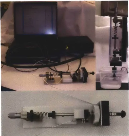
shape and size. By varying the spring stiffness, inertial mass, and displacement, the velocity of the tool can be prescribed. The spherical tip shown in Figure 3-3 has a diameter of 10mm, and footprint of the tool is 200mm x 75mm x 50mm. Table 3.1 outlines the design parameters of the tool, while Figures 3-3 and 3-4 show a schematic of the tool as well as the interface with the data acquisition system.
Although this tool may be mounted in multiple configurations (vertical or horizontal), it was designed to be vertically mounted as shown in Figure 3-4. The actuating spring is precompressed and held in the compressed position by a trigger-release mechanism. Upon activating this flexural release, motion of the indenter into the tissue is initiated. The motion comes to an
abrupt stop when the stop on the shaft meets the adjustable endstop of the tool.
Displacement Transducer Replaceable Tip Micrometer & components for spring compression
7
D 0J!_
JForeSn Trigger reSn Release Adjustable StopIFigure 3-3: Design details of in vivo spring-loaded material testing device
The force data were collected through the entire range of motion. However, upon impact the force response spiked sharply; the force sensor was not designed to handle such impact forces. We incorporated an accelerometer to better understand the inertial loads, but unfortunately, the 50g accelerometer also saturated upon impact. This finding poses a significant design challenge. In order to implement this tool, sensors more tolerant to impact conditions must be incorporated.
3.2.3 In vivo dynamic indentation tool
For applications of interest to the current study, i.e. in-vivo testing of biological tissue, a compact, portable testing tool is necessary: the final tool design presented is a large excursion
adaptation of an approach proposed by Ottensmeyer
[62].
Components
In order to measure the behavior of the tissue under large strain and high strain rate conditions, we chose a voice coil motor (H2W Technologies, Valencia, CA) with an excursion of 12.5mm. The selected voice coil is a moving magnet actuator supplied with internal bearings and a moving shaft. The main advantage of the moving magnet actuator is that there are no moving leads, since the coil assembly is stationary. Voice coils operate on the principle of the Lorentz Force Equation (see Equation 3.1), where B is the flux density (Tesla) and I is the current (amps) running through the coil.
F = B x I (3.1)
Simply stated, a current-carrying conductor placed in a magnetic field will have a force exerted upon it. This force is proportional to the direction and magnitude of the current and the flux density field. Since the permanent magnet flux density field is fixed, the direction of the linear displacement depends on the polarity of input current. The amount of force produced is directly proportional to the magnitude of the input current. The chosen voice coil motor
(NCM-05-08-0052J]BT) can provide a maximum continuous force of 2.25N and a transient peak force of 6.75N. The motion of the motor is driven through a linear power amplifier (Quanser, Ontario,
30 25- 020- 015-0 10- 5-o 1 2 3 4 5 6 7 Depth of Indentation (mm)
Figure 3-5: Tool capabilities given by the frequency of oscillation versus the depth of indentation travelling in air
actuators. The unit operates from a 30V power supply and provides a maximum continuous current of 7A. Springs (k=350N/m) were installed on the proximal and distal ends of the shaft between the motor end stops and the motor housing. The springs transform the system from a nearly pure inertial system to a spring-mass system that has a natural equilibrium point and can be controlled more easily. The force output (current capacity) limits the operational frequency of the system for sinusoidal oscillations: with the current moving mass of 40.0g, the tool can operate at a maximum frequency of 30Hz for 1mm displacement amplitude. For larger displacement amplitudes, the maximum frequency decreases (e.g. at a 7mm amplitude the frequency is limited to ~10Hz). Figure 3-5 describes the tool's capabilities when operating in air.
An excursion of 7mm at 10Hz roughly corresponds to a maximum velocity of 70mm/s and incorporating a 12.5mm diameter spherical indenter corresponds to a strain rate of
approxi-mately etool = 11.2s- 1 where strain is defined as the ratio between the excursion and the radius
of the indenter. To measure the shaft displacements, a sensor known as a linear variable differ-ential transducer (LVDT) (TransTek, Ellington, CT) is placed at the proximal end of the tool, and shares a shaft with the voice coil motor. The LVDT consists of a primary coil and two
Voice Coil Motor H2 W Technologies, NCM-05-08-0052JBTj Displacement Transducw TransTek, DC-DC LVDT, Model 243 El 0' rC'4 1 I-Force Sensor Honeywell Model 31 Spherical Tip 4 8mm travel 215 mm
Figure 3-6: A cross-sectional view of the in vivo dynamic indentation tool
Inertial mass Voice coil motor
Continuous output force Maximum peak force Force sensor max load Displacement sensor Full range Working range 40.0 g 2.25N 6.75N 10.ON 12.5mm 8.0mm
Table 3.2: Specifications of dynamic indentation surface tracking (DIST) tool design
secondary coils wound on an armature. The primary coil is excited and induces a voltage in the secondary coils. The difference between the voltage of these output coils results in motion of the core (armature) with respect to the coils. A 10OOg subminiature compression/tension load cell (Honeywell, Columbus, OH) is attached at the distal end of the tool. The force sensor is mounted as closely as possible to the indenter tip to minimize measuring the inertial loading of components beyond the tip itself. This bonded foil strain gage sensor is excited using a 12V DC power supply. The force sensor differential output signal passes through a universal in-line amplifier (Honeywell, Columbus, OH), which amplifies il5mV output signal to ±10V. The indenter tip is interchangeable; in the current design, a 12.5mm diameter hemispherical indenter tip has been selected. The total moving mass of 40.Og consists of the motor/LVDT shaft, the force sensor, the tip and the attachment components. Figure 3-6 illustrates the tool, while Table 3.2 describes the operating characteristics. For an imposed indenter displacement history the force sensor measures the corresponding reaction force exerted by the material on the indenter tip.
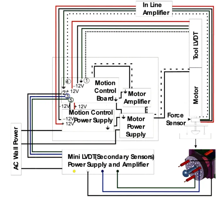
Control and data acquisition system
The original tool design proposed to run the displacement of the device open loop and output the resulting force exerted on the tissue. Although this approach is reasonable, we felt that
by building a closed-loop system, the motion could be controlled much more effectively and
the motion frequency could be driven to higher regimes than if operated in open loop mode. To achieve closed-loop control, a motion control board (Galil, Rocklin, CA) was selected. This motion controller can operate 2 axes simultaneously and can capture up to 40 digital and 8 analog inputs. It contains a 32-bit microprocessor that runs independently of the laptop thereby not interfering with or causing clock speed delays. The motion control communication with the laptop occurs via an RS232 port. The force sensor output and displacement of LVDT shaft are recorded using the analog input channels of the data acquisition system. Data may be acquired at a maximum of 250 samples/s for up to 8000 available array elements. This closed-loop control system operates in displacement-control mode for arbitrary loading histories (stress relaxation, constant strain rate load/unload ramps, sinusoidal oscillation, etc) within a range
architecture and wiring for the motor, linear amplifier, controller, and sensors. The ground loop is reinforced by ensuring that the power supplies and amplifier are connected to the same
ground lug. This is a particularly important feature to reduce noise in the system.
3.3
Mounting configurations
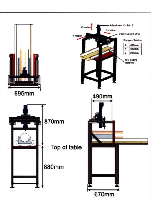
3.3.1 MI frame configuration
Both the spring tool and the dynamic indentation tool may be mounted to a testing frame constructed of 6061-T6 aluminum profiles (MiniTec Framing Systems, LLC Victor,NY). The system design was motivated by the in vivo study that will be performed; this entailed providing a range of motion for the tool that allows for adjustments to accomodate a 50kg porcine animal. The study was also designed so that brain MRI images of the porcine animal model may be acquired between each testing sequence. For this reason, the frame accommodates the MRI table from the General Electric 3.0T MRI system (GE Healthcare, Chalfont St. Giles, UK).
Details of the system footprint and ranges of motion may be found in Figure 3-8. The first axis of motion is provided in the y-direction using two linear rails. The x-axis is mounted to the y-axis and contains one linear rail. These two axes (x- and y-) are free floating and do not have encoders, motors or ballscrews to dial-in the precise location. The intent was to grossly locate the x- and y- axes and use locks on each rail to fix the position at the desired location. The vertical z-axis motion is actuated using a manual BiSlide with counter (Velmex, Bloomfield, NY). This positioner was selected to provide 250mm of manually adjusted linear motion. Because of the delicate nature of the in vivo porcine brain tissue, we chose to manually actuate the z-axis such that the initial position of the indenter relative to the brain tissue could be precisely adjusted (screw pitch= turn/cm). Attached to the z-axis is a 3-axis rotary
positioner (Newport Corp, Irvine, CA) that provides 360' rotation along its axes and ±250 of
rotational adjustment in the other two axes. This additional feature allows the instrument to be aligned orthogonal to the measurement surface. Designing the frame to be fully adjustable in six axes (3-linear, 3-rotational) enables the user to accurately position the tool to the desired testing location.
In
Une
... ..
.. .. .. .. ..
Am plifier ...
*o : 00 1- 2V LO-12V
Control--
Motor-ba rd+
-
Amplifier:
r12\
12v
Motion Control
--12V
rLupi
+
Motor
Fore
+
1 2
\rwer
Supp
y
Sensor.__
+
Flwe
r
LuPpRY
Mini LVDT(Secondary Sensors)
Flwer
Supply
and Amplifier
-
-I
I
Figure 3-7: Schematic of data acquisition and motion control architecture for indentation device
m~m
IL
I
Z-rnaiOnj o--- Adjuatmnt Knob in Z X-action
Y-MoionBack Suppoft StruA R&nge of Mobio X 410mrn Y 41em Z 1250mmn
I.
695mm
870mm
rTop of table
880mm
Figure 3-8: Detailed drawings of frame footprint and the ranges of motion in the linear axes