Dexterous Manipulation with Simple Grippers
by
Nikhil Chavan-Dafle
Submitted to the Department of Mechanical Engineering
in partial fulfillment of the requirements for the degree of
Doctor of Philosophy in Mechanical Engineering
at the
MASSACHUSETTS INSTITUTE OF TECHNOLOGY
May 2020
c
○ Massachusetts Institute of Technology 2020. All rights reserved.
Author . . . .
Department of Mechanical Engineering
May 1, 2020
Certified by . . . .
Alberto Rodriguez
Associate Professor
Thesis Supervisor
Accepted by . . . .
Nicolas Hadjiconstantinou
Department Graduate Officer
Dexterous Manipulation with Simple Grippers
by
Nikhil Chavan-Dafle
Submitted to the Department of Mechanical Engineering on May 1, 2020, in partial fulfillment of the
requirements for the degree of
Doctor of Philosophy in Mechanical Engineering
Abstract
This thesis focuses on enabling robots, specially those with simple grippers, to dexterously manipulate an object in a grasp. The dexterity of a robot is not limited to the intrinsic capability of a gripper. The robot can roll the object in the gripper using gravity, or adjust the object’s pose by pressing it against a surface, or it can even toss the object in the air and catch it in a different pose. All these techniques rely on resources extrinsic to the hand, either gravity, external contacts or dynamic arm motions. We refer to such techniques collectively as “extrinsic dexterity”.
We focus on empowering robots to autonomously reason about using extrinsic dexterity, particularly, pushes against external contacts. We develop mechanics and algorithms for simulating, planning, and controlling motions of an object pushed in a grasp. We show that the force-motion relationship at contacts can be captured well with complementarity constraints and the mechanics of prehensile pushing in a general setting can be formulated as a mixed nonlinear complementarity problem. For computational efficiency, we derive the abstraction of the mechanics in the form of motion cones. A motion cone defines the set of object motions a pusher can induce using frictional contact. Building upon these mechanics models, we develop a sampling-based planner and an MPC-based controller for in-hand manipulation. The planner generates a series of pushes, possibly from different sides of the object, to move the object to a desired grasp. The controller generates local corrective pushes to keep the object close to the planned pushing strategy. With a variety of regrasp examples, we demonstrate that our planner-controller framework allows the robot to handle uncertainty in physical parameters and external disturbances during manipulation to successfully move the object to a desired grasp.
Thesis Supervisor: Alberto Rodriguez Title: Associate Professor
Acknowledgments
I would like to take this opportunity to thank my advisor, Prof. Alberto Rodriguez for his continuous support and guidance. The freedom and encouragement he provided to try new ideas, get stuck, keep pushing, and learn made this journey a very exciting and rewarding experience. I feel fortunate to have him as a life-long mentor and a friend.
I am grateful to Prof. Matthew T. Mason who gave me an opportunity to take my baby steps into the world of Robotic Manipulation during my master’s studies at CMU. I feel the idea of Extrisnic Dexterity, in an abstract sense, reflects the open atmosphere in the MLab that let me explore different ideas and ways to shape myself and to grow. I would also like to thank Prof. Russ Tedrake and Prof. Neville Hogan who as my thesis committee members actively guided my research and helped me make it well-rounded.
The time at MIT wouldn’t have been as enjoyable without each and every member of The MCube Lab. I am lucky to have some of my best friends as my labmates. Particularly, I would like to thank Nima, Francois, and Rachel for everything, for all the wise advice and all the comforting support you have provided in need.
Last but not least, I am forever grateful to my family for all their support, love, and understanding. From the bottom of my heart, I thank my parents, Narsingh and Vandana, and my sister, Nisha. Thank you Mommy for being so strong and supporting me to continue my journey during this difficult last year. Thank you Papa for making us strong enough to bear your absence and to keep pursuing our dreams.
Contents
1 Introduction 19
1.1 Contributions of the Thesis . . . 20
1.1.1 Extrinsic Dexterity . . . 20
1.1.2 Planning and Control for Prehensile Pushing . . . 21
1.2 Scope of the Thesis . . . 25
2 Background and Related Work 29 2.1 Robotic Manipulation . . . 30
2.1.1 Manipulation using Intrinsic Dexterity . . . 30
2.1.2 Manipulation using Extrinsic Dexterity . . . 30
2.2 Planning and Control through Contact . . . 32
2.2.1 Hard Models and Soft Models . . . 32
2.2.2 Sampling-based and Optimization-based Methods . . . 33
2.2.3 Task Generality and Planning/Control Efficiency . . . 34
3 Mechanics of Pushing 37 3.1 Contact Modelling . . . 37
3.1.1 Coulomb Friction . . . 39
3.1.2 Generalized Friction Cone . . . 41
3.1.3 Limit Surface . . . 42
3.2 Pushing Dynamics with Complementarity Constraints . . . 45
3.2.1 Modeling and Formulation . . . 45
3.2.3 Experimental Validation . . . 48
3.2.4 Observations and Discussion . . . 51
3.3 Pushing Dynamics with Motion Cones . . . 54
3.3.1 Modeling and Formulation . . . 55
3.3.2 Analytical Computation of Motion Cones . . . 60
3.3.3 Experimental Validation of Motion Cones . . . 64
3.3.4 Discussion . . . 65
4 Planning Prehensile Pushes 69 4.1 Sampling-based Long Horizon Planing . . . 70
4.2 Planning with Complementarity Constraints . . . 74
4.2.1 Unit-step Propagation using Inverse Dynamics . . . 75
4.2.2 Regrasp Experiments . . . 75
4.2.3 Discussion . . . 82
4.3 Planning via Motion Cones . . . 83
4.3.1 Unit-step Propagation using Motion Cones . . . 84
4.3.2 Regrasp Experiments . . . 85
4.3.3 Discussion . . . 87
5 Prehensile Pushing under Uncertainty 91 5.1 Robust Planning using Mechanics of Pushing . . . 91
5.1.1 Uncertainty at Pusher-Object Interaction . . . 92
5.1.2 Uncertainty at Gripper-Object Interaction . . . 93
5.1.3 Fixtureless Fixturing . . . 95
5.2 Online Control using Motion Cones . . . 99
5.2.1 MPC Framework with Motion Cone Constraints . . . 99
5.2.2 Control Experiments . . . 101
6 Discussion 107 6.1 Summary . . . 107
6.1.2 Mechanics of Pushing: Applications to Regrasp Planning and Control108
6.2 Extensions of the Thesis . . . 109
6.2.1 Robust Planning and Control Through Reachable Spaces . . . 109
6.2.2 Manipulation with Multi-finger Grippers and Multi-arm Robots . . 110
6.2.3 Hardware Design for Dexterity . . . 110
6.2.4 Dexterous Manipulation with Tactile Feedback . . . 111
6.2.5 Pick-Regrasp-Place . . . 112
6.3 Open Research Directions . . . 113
6.3.1 Compact Mechanics Models for Manipulations in 3D . . . 113
6.3.2 Algorithmic Design for Dexterity . . . 114
List of Figures
1-1 Regrapsing objects using extrinsic dexterity: an object in a grasp is ma-nipulated by using (left) gravity alone, (center) induced inertia, and (right) external pushes. . . 20 1-2 A grasp graph for a triangular prism built using extrinsic dexterity. Solid
arrows represent implemented regrasps while dashed arrows indicate other possible ones. . . 21 1-3 An example of prehensile pushing – an aluminum object is reconfigured in
a grasp by pushing it against the environment from different sides. . . 22 1-4 Examples of general prehensile pushes: driving a screw, pushing against
the ground, and pivoting about an edge . . . 23 1-5 Examples of planar manipulation: pushing an object (a) on a horizontal
surface, (b) on an inclined surface, (c) in a grasp in the gravity plane, and (d) in a grasp in a tilted plane . . . 24 1-6 Manipulating a T-shaped object in a parallel-jaw grasp by pushing it against
features in the environment. The manipulation is shown from a side view. . 26 1-7 (left) An object held in a parallel-jaw gripper is pushed against a fixed
feature in the environment. (right) The planner models this interaction as if the object is held by a fixed gripper and pushed by a moving environment, i.e. a pusher. . . 27 3-1 Schematics of a prehensile pushing scene with important frames labeled. . . 38 3-2 Different contact geometries: point, line and planar, modeled as sets of
3-3 (Left) The line pusher contact in this planar pushing example is modelled with two point contacts. The pusher contact frames and the object frame are drawn in the figure. The two-dimensional Coulomb friction cones at the point contacts are shown in the respective contact frames. (Right) The generalized friction cone of the line pusher provides the object frame rep-resentation of the set of forces the two point contacts can offer collectively. The the top and bottom facets of this cone are the generalized friction cones of the two point contacts modelling the line contact. Consequently, the con-vex hull of these two facets takes the form of a polyhedral cone with four facets and represents the generalized friction cone of the line pusher. . . 41
3-4 (Left) Ellipsoidal approximation of the limit surface at the finger contact. For a wrench 𝑤s on the boundary of the limits surface, the twist at the
contact 𝑣s is normal to the limit surface. (Right) The wrench 𝑤s and the
corresponding object motion is shown in the manipulation scene. . . 43
3-5 Experimental setup with six-axis force-torque sensors fitted to both finger-tips of the gripper and in the environment. A 3D printed Vicon marker is attached to the left end of the object for accurate and fast position tracking. The setup allows us to capture ground truth for motions and contact forces at 250 Hz. . . 49
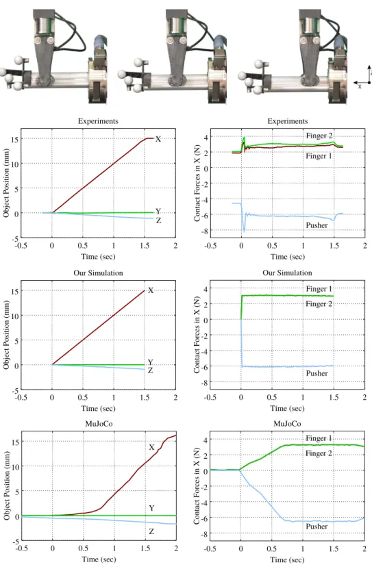
3-6 Example of a linear horizontal push with gripping force of 20 N, pushing velocity of 10 mm/sec. Note the motion of the object in the -Z direction, as the gripper moves straight in -X direction. The plots show the experimental data captured for motions on the left and force on the right (top), and simu-lated data with our dynamics model (mid) and with the soft-contact model in MuJoCo [95] (bottom). Nominally, the pushing action starts at 0 sec and ends at 1.5 sec. . . 50
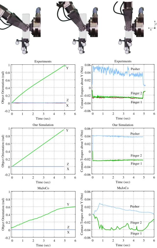
3-7 Example of pivoting with grasping force of 20 N, pushing velocity of 10 deg/sec, and pusher at the center of the object. Experimental data (top) Simulation data (mid) and MuJoCo data (bottom) for object orientation and contact torques at the contacts about the axis of pivoting for one of the pivoting experiments . . . 52 3-8 To make a push inside the gravity-free motion cone also stable in a scenario
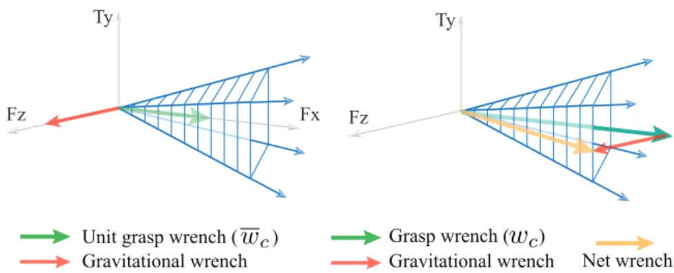
with gravity, the unit grasp wrench can be scaled such that the net pusher wrench required for the desired push falls inside/on the generalized friction cone of the pusher. . . 58 3-9 Graphical illustration of the motion cone construction procedure applied to
two different planar pushing systems: (top) pushing an object on a hori-zontal plane with a point pusher and (bottom) pushing an object in a grasp in the gravity plane. From left to right, the construction steps portray modelling of the forces involved in the task (Force Modelling), solving for the set of force-balance solutions in wrench-space (Force Resolution), and finally computing the set of object twists corresponding to the force-balancing solutions (Motion Resolution). This set of object twists is the motion cone. . . 61 3-10 The analytically computed wrench cone (𝑊s), motion cone (𝑉obj), and
polyhedral approximation to the motion cone (𝑉obj) for the configuration
in Figure 1-7 and 45 N grasping force. Note that the surfaces defining the motion cone (𝑉obj) are curved. . . 63
3-11 Experimental setup used for the data collection for motion cone validation as well as for the regrasp examples in Chapter 4 and Chapter 5. . . 64
4-1 Simulated motion of the object and snapshots from the experiment for a pushing sequence generated by the planner. Object motion is shown from a side view; finger contact is a circular patch modelled with points con-tacts (shown in green) and pusher contact is a line/edge contact (shown in magenta). . . 76
4-2 Simulated motion of the object for a pushing sequence for a light-weight plastic object. Note that only side pusher is used throughout and downward sliding of the object is minimal. . . 77 4-3 Object motion in the grasp as predicated by the planner and as observed
in the experiment for the example shown in Figure 4-1. Mean values for 10 experimental runs are shown, with error-bars indicating the variation observed during these runs. . . 78 4-4 A pushing sequence for pivoting the aluminum object in a parallel-jaw
grasp. The pushing sequence involves discrete pusher switch-overs to push the object from different facets to eventually get to the desired pose. . . 78 4-5 Pivoting strategy generated using a single pusher contact on right face of
the object. . . 79 4-6 Object motion in the grasp as predicated by the planner and as observed
in the experiment for the example shown in Figure 4-5. Mean values for 10 experimental runs are shown, with error-bars indicating the variation observed during these runs. . . 80 4-7 Evolution of the rolling contact and orientation of the ball in the grasp for
the trajectory planned to rotate the ball about Z axis. Finger contacts are shown in green, while the contact between the ball and the ground is shown in magenta color. . . 81 4-8 Object pose in the grasp at the beginning, middle and end of the rolling
trajectory. Black, silver and golden paint marks on the ball, show that the object effectively rotates by 90 degrees about vertical (Z) while net orientation about other two axes (X and Y) go close to zero as before. The supplemental video shows the actions involved better. . . 81 4-9 Since the sampled grasp configuration is outside the motion cone, it is
pro-jected on the motion cone. The propro-jected configuration is selected to grow the planning tree. . . 84
4-10 (left) Example motion cone of an object moving in the vertical plane. The pusher can move the object along any direction [𝑉𝑥, 𝑉𝑧, 𝜔𝑦] inside the
mo-tion cone. (right) A plan via momo-tion cones. Momo-tion cones capture local reachability. A path in the tree of motion cones generates a pushing strat-egy to move an object. . . 85 4-11 Simulation and experimental run for a pushing strategy to regrasp the
alu-minum object with low friction pushers. In the simulation figure (top), the finger and pusher contacts are shown in green and magenta color respectively. 86 4-12 Simulation and experimental run for a pushing strategy to regrasp the
alu-minum object with high friction pushers. . . 87 4-13 A pushing strategy for [𝑋, 𝑍, 𝜃𝑌] regrasp. In simulation, the direction of
gravity remains constant in the pusher frame, because in real experiments, the pushers are fixed features in the environment. . . 88 4-14 Simulation and experimental run to manipulate a T-shaped object. . . 88
5-1 The motion cone shifts towards the gravity-free motion cone as the friction at the gripper increases due to the increased grip force. The intersection of the gravity-free motion cone and the motion cone is shown by the dotted region for the two grip forces. The motions inside the motion cone that are outside the gravity-free motion cone are feasible only by exploiting the gravitational force on the object (in 𝑍 direction). For higher friction at the gripper than expected, these motions may no longer be feasible. One of such motions that is shown in red falls outside the motion cone when the grip force is increased. All the motions inside the intersection however, will always be feasible for the higher than expected friction at the gripper. . 94 5-2 Simulated motion of the object and snapshots of the experimental run for a
pushing strategy to offset the object in the grasp using low coefficient pushers. 95 5-3 Simulated motion of the object and snapshots of the experimental run for a
5-4 Simulated motion of the object and snapshots of the experimental run for the T-shaped object. . . 97 5-5 Displacement of the object with respect to the environment for the regrasp
action shown in Figure 5-2. During pushing, the object sticks to the envi-ronment and moves by a negligible amount as the fingers slide on it. . . 98 5-6 Displacement of the object with respect to the environment for the regrasp
action shown in Figure 5-3. . . 98 5-7 (left) A pushing path planned for desired prehensile pushing manipulation.
Color of the knot points represent the pusher used to get to that knot point. (right) Based on the current object pose in the grasp and corresponding closest pose on the original path, the controller selects 𝑘-step segment of the original path as reference path to track. . . 99 5-8 The controller tracks the pose of the object and maintains it close to the
planned path to achieve the desired goal grasp accurately. . . 102 5-9 The planner generates a pushing path with an inaccurate estimation of the
start pose for the object in the grasp. The controller handles the inaccurate initialization and generates local corrective pushes to bring the object pose back towards the original path, finally reaching close to the goal pose. . . . 102 5-10 The controller corrects for external perturbations during the execution of
the planned prehensile pushes. The red arrows show the object pose changed in grasp due to the external disturbances. The controller brings the object back towards the planned path to complete the desired regrasp. . . 103 5-11 Integrated re-planning kicks-in when the controller alone is not sufficient
to achieve the desired goal object pose successfully. In this example, the controller triggers the planning routine at the pose marked as Start 2, since it can not raise the object much up in the grasp along Z axis using the side pusher. With a new plan from Start 2, the controller can move the object to the goal grasp. . . 104 6-1 A sketch of Pick-Regrasp-Place manipulation system. . . 112
List of Tables
3.1 Important mathematical notations used throughout the thesis. . . 38 3.2 We validate the polyhedral approximation of the motion cone across three
setups by characterizing thousands of prehensile pushes by the slip ob-served at the pusher contact. . . 66 4.1 Physical properties of the objects in experiments . . . 76 4.2 Planning times (sec.) for approaches using motion cone, stable check [12]
Chapter 1
Introduction
Dexterous manipulation, understood as the broad capability to adapt a grasp on an object, facilitates the inconspicuously complex process involved in between picking up and using an object. It allows us to pick up an object without worrying much about the consequences of the particular acquisition grasp down the manipulation pipeline. Today’s robots, spe-cially those with simple grippers, lack the necessary dexterity to do so, which significantly strains their broad manipulation capabilities.
With lack of dexterous manipulation skills, even most advanced robots in use, like those in factories, are no more than pick and place machines. A common approach to address the need for regrasping is to avoid it by using part feeders, which take care of reorienting parts and presenting parts to a robot as needed for the application. A second common approach is to have custom-designed fixtures around the robot which act as intermediate part holders and to achieve the desired regrasps using series of pick-place-pick actions. This makes automating an assembly line as well as the assembly process itself an expensive and time-consuming affair. In the future, moving beyond the controlled environments of factories, such as in homes, hospitals, and field, manipulation dexterity will be even more crucial for robots to be effective or even useful at all. It’s not often possible to pick up an object or a tool in a pose that is immediately useful for its application. In-hand manipulation skill, especially with simple and easily accessible hardware, will enable robots of today to pick up objects however possible, regrasp them in hand, and then use them at the desired application.
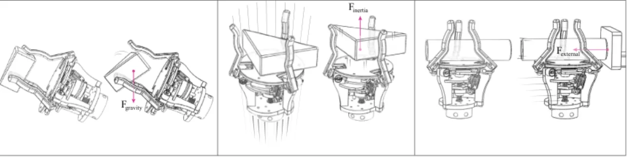
Fgravity
Fexternal Finertia
Figure 1-1: Regrapsing objects using extrinsic dexterity: an object in a grasp is manipulated by using (left) gravity alone, (center) induced inertia, and (right) external pushes.
1.1
Contributions of the Thesis
In this thesis, we present an approach called Extrinsic Dexterity that allows robots to reason about effective use of gravity, dynamics motions and even contacts with the environment to manipulate objects in hand. We develop tools and algorithms that enable robots to au-tonomously plan and control their motions for desired dexterous manipulation.
1.1.1
Extrinsic Dexterity
In the robotics research literature “dexterity” often refers to the manipulation of an object in the hand, with the hand. By “extrinsic dexterity” we mean the manipulation of an object inthe hand, using resources extrinsic to the hand. For example, as shown in Figure 1-1, if you tilt your hand so that an object rolls from your fingertips to your palm, you are using gravity, not just your hand. If you toss an object upwards from your palm and catch it in your fingertips, you are using object inertia and arm acceleration, not just your hand. If you press two chopsticks against the tabletop to even them up, you are using the surface of the table and arm motions, not just your hand. In each case, you can do more, better, or faster by exploiting resources extrinsic to the hand.
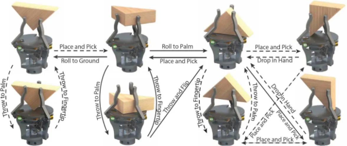
We explore the application of extrinsic dexterity to regrasp an object in hand. We develop twelve regrasp actions, all open-loop and hand-scripted, and evaluate their effec-tiveness with over 1200 trials of regrasps and sequences of regrasps, for three different objects [13, 14]. We show that extrinsic dexterity complements the intrinsic capabilities
Figure 1-2: A grasp graph for a triangular prism built using extrinsic dexterity. Solid arrows represent implemented regrasps while dashed arrows indicate other possible ones.
of the gripper and enables a repertoire of regrasp actions sufficient to reach many different grasp types in a given grasp taxonomy, like the one shown in Figure 1-2. We call it a Grasp Graph. Grasp graphs allow us to see the connectivity of grasps to plan long sequences of regrasps for desired in-hand manipulation.
Generalizing in-hand manipulations so they can be applied across a broad range of grasps, objects, and hands, is an enormous challenge. Nonetheless, extrinsic dexterity has advantages that justify this work. Extrinsic dexterity offers an incomparable ability to change grasps. In addition, by exploiting resources extrinsic to the hand, we shift part of the complexity of the manipulator to a possibly modular and adaptable environment. This allows the use of simpler hands and manipulators which can be cheaper, lighter, smaller, and readily available.
1.1.2
Planning and Control for Prehensile Pushing
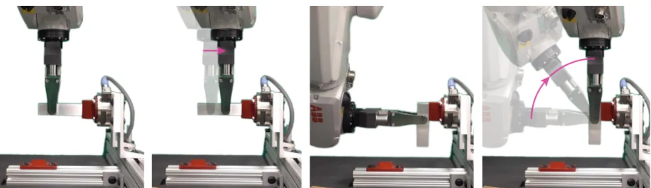
With the goal of enabling robots to autonomously plan in-hand manipulations, we focus on a particular mode of extrinsic dexterity where an object in a grasp is manipulated by external pushes. We call it Prehensile Pushing, since the object is stably grasped in a gripper while being manipulated by a series of external pushes [10]. Figure 1-3 shows one of such examples of in-hand manipulation using prehensile pushes.
Figure 1-3: An example of prehensile pushing – an aluminum object is reconfigured in a grasp by pushing it against the environment from different sides.
Mechanics Formulation and Experimental Validation [Chapter 3]
An object in a grasp moves under the influence of the total wrench acting on it, which is a net effect of local forces and torques at all the contacts on the object and object iner-tia. Accurately modelling the forces and relative motions at rigid contacts while keeping it computationally efficient, is a difficult problem. Frictional contact naturally introduces under-actuation to the system. Contact can only push and not pull. It can apply only a set of forces and torques in certain directions. In Chapter 3, we explore two different approaches to model the force-motion relationship at contacts and formulate the instantaneous dynam-ics of pushing. First with detailed complementarity-based contact modeling and then by building motion-space abstraction of dynamics in the form of motion cones.
Prehensile pushing with complex contact interactions can be formulated as a general rigid body dynamics problem with frictional contact modelled with complementary con-straints. In Section 3.2, we show that, the resulting Mixed Nonlinear Complementarity Problem (MNCP) can be solved as an optimization problem to simulate the instantaneous motion of the object in the grasp when pushed or to predict an instantaneous external push necessary to move the object in the grasp as desired. We conduct a variety of prehen-sile pushing experiments on a instrumented experimental platform, which can track the pose of an object in a grasp and record forces at all the contacts. We observe that the complemetarity-based dynamics formulation is able to capture the dynamics of pushing accurately, but suffers from high computational cost associated with solving the MNCP.
Figure 1-4: Examples of general prehensile pushes: driving a screw, pushing against the ground, and pivoting about an edge
motion cones [67] and extend it to general pushing tasks including prehensile pushing. A motion cone is the set of feasible motions that a rigid body can follow under the action of a frictional push [16, 18]. We can think of it as a representation of the underactuation inherent to frictional contacts. Motion cones are a practical geometric representation that abstracts the algebra involved in simulating frictional contact dynamics, and provides direct bounds on the set of feasible object motions. In Section 3.3.1, we show that the motion cone for a general planar push is defined as a cone with low-curvature facets, and propose a polyhedral approximation for efficient computation. With thousands of pushes in different object-grasp-pusher configurations, we validate the accuracy of the computation of motion cones.
Regrasp Planning[Chapter 4]
Given a pair of start and goal grasps on an object, we want a robot to plan a sequence of pushes to reconfigure the object in the grasp. Building upon the dynamics models we developed in Chapter 3, we design a sampling-based planner for in-hand manipulations us-ing prehensile pushes. A samplus-ing-based plannus-ing architecture explores the configuration space of different grasps and attempts to connect different grasps using a dynamics formu-lation which guides a unit-step propagation of the planning tree. The high-level planning architecture is based on the transition-based RRT* (T-RRT*) formulation which uses tran-sition tests for efficient exploration of the configuration space and the underlying RRT*
Z X Y mg Pusher mg Gripper Pusher mg Y Z X mg Pusher Z Y X Z X Y mg Gripper Pusher θ (a) (b) (c) (d)
Figure 1-5: Examples of planar manipulation: pushing an object (a) on a horizontal surface, (b) on an inclined surface, (c) in a grasp in the gravity plane, and (d) in a grasp in a tilted plane
routines for building and rewiring connections in the planning tree to optimize for cost criteria. We use the transition tests to promote the stochastic exploration towards the goal grasp and cost definitions in RRT* routines to reduce the complexity of pushing plans by reducing the number discrete contact switchovers. In Section 4.2.2 and Section 4.3.2, we demonstrate the performance of our planners with a variety of regrasp examples with dif-ferent objects and discuss their key notable features.
For general in-hand manipulations in three dimensions (Figure 1-4), the MNCP-based inverse dynamics solver drives the low-level unit step propagation and solves for the instan-taneous push required to move the object towards the sampled pose. Although this method results into a very general in-hand manipulation planner which can handle difficult regrasp tasks with complex contact interactions, planning times can be upto tens or hundreds of minutes, due to computational complexity of the dynamics solver.
On the other hand, for planar in-hand manipulations (Figure 1-5), we demonstrate that the dynamic feasibility knowledge in the form of motion cones can be directly used for the unit-step propagation of the planning tree. Motion cones define the set of feasible pushes, or in other words the set of reachable object configurations. Using motion cones as reachability bounds directly in the configuration space allows the planner to rapidly explore the configuration space and generate dynamically feasible pushing strategies in a fraction of a second.
Robust Regrasp Planning and Control [Chapter 5]
In practice, the dynamics of the manipulations involving contact interactions can be noisy due to uncertainty in physical parameters such as frictional properties, grasping force, and object mass. Based on the mechanics of pushing and motion cones, we propose differ-ent approaches for planning in-hand manipulations that are robust against uncertainty in physical parameters. In Section 5.1, we show that conservative approximations of motion cones, and a careful selection of the orientation of the pusher with respect to gravity, yield increased reliability, and, in some cases, invariance. Moreover, by exploiting motion cone bound constraints in MPC framework, we design a controller to handle external distur-bances during the execution of the pushing strategies. The controller keeps track of the pose of the object in the grasp and iteratively generates local pushing paths to keep the object close to the planned path and to reach the goal grasp precisely. During the regrasp experiments in Section 5.2.1, we poke the object during the manipulations. The experi-mental data shows that our motion cone based integrated planner-controller can correct for the added noise and push the object successfully to the desired pose in the grasp.
1.2
Scope of the Thesis
We develop the concept of extrinsic dexterity in a broad fashion and demonstrate its appli-cation with a large repertoire of hand-scripted regrasp actions. However, the development of mechanics, planning, and control techniques discussed in this thesis is focused on only one of the modes of extrinsic dexterity – prehensile pushing. Prehensile pushing can be performed with simple grippers and robots, and at low speeds. It provides large span for control, in both actuation space and actuation time sense. With minimal system hardware requirements, we hope that the manipulation algorithms and methods we develop for pre-hensile pushing in this thesis will provide wider scope for applications and extension of this work.
The theory and tools developed in thesis rely on the following assumptions:
manipu-Figure 1-6: Manipulating a T-shaped object in a parallel-jaw grasp by pushing it against features in the environment. The manipulation is shown from a side view.
lations can be in three dimensions like those shown in Figure 1-4. The configuration space, i.e., the space of object grasps, is six-dimensional (three for position and three of orientation). For the planner using motion cones, the manipulations are limited to planar regrasps in a parallel jaw-grasp like those shown in Figure 1-5. The configu-ration space is three-dimensional; the object can translate and rotate in the manipula-tion plane. The desired regrasp is specified by the initial and final object pose in the grasp, as illustrated in Figure 1-6.
∙ Gripper: a parallel-jaw gripper with force control. Although, the planner using MNCP-based dynamics is not limited to planar manipulations and can handle grip-pers with varied kinematics, the examples considered in this thesis are limited to using a parallel-jaw gripper. The gripping force remains constant during the manip-ulation. The contacts between an object and gripper’s fingers could be of any planar geometry (patch, line or point contacts). The friction coefficient between the fingers and the objects is known, with some bounded uncertainty.
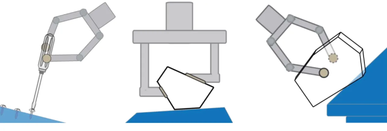
∙ Objects: three dimensional objects grasped in a parallel-jaw gripper. We assume we know the geometry and mass of the object. The outline of the object in the manipulation plane can be non-convex. For example, the pushing strategy shown in Figure 1-6 for T-shaped object is generated by the motion cone based planner. We assume that the contact geometry at finger contacts does not change during the manipulation.
Gripper
Environment Pusher
Gripper
World Perspective Planner Perspective
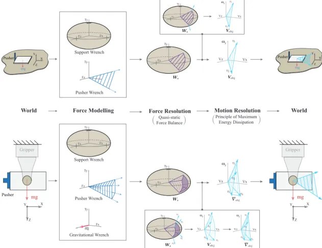
Figure 1-7: (left) An object held in a parallel-jaw gripper is pushed against a fixed feature in the environment. (right) The planner models this interaction as if the object is held by a fixed gripper and pushed by a moving environment, i.e. a pusher.
corners) to push against. These provide affordances of controlled patch, line or point contacts. We know the location and geometry of the features with precision and their friction coefficient with some bounded uncertainty.
The planning framework developed in this thesis generates a sequence of external pushes that moves the object from the initial to the final grasp. In our implementation in this thesis, the external pushes are executed by a robot pushing the grasped object against fixed features in the environment. These pushes could also abstract the interactions with a second robot arm or with extra fingers in a multi-finger gripper.
Figure 1-7 shows the schematic from the planner’s perspective: in the planning phase, we imagine the alternate perspective where the parallel-jaw gripper is fixed in the world and the environment is a “virtual” pusher with full mobility pushing the grasped object. Planning external pushes is then equivalent to planning the motion of the virtual pusher to achieve the desired regrasp. The “virtual” pusher motion is then rendered in the real world by instead moving the gripper using the robot.
Chapter 2
Background and Related Work
Dexterous manipulation skill can enable flexible robotic solutions to pick up a variety of objects and tools, regrasp them in hand, and use them. Unfortunately, bogged by the lack of practical and reliable solutions, the dominant approach is to avoid the need for regrasp. Manufacturing automation avoids regrasp through the design of specialized grippers, part feeders, work-holding fixtures, and tools [68]. Avoiding the need for in-hand manipulation is also a common consideration in the design of surgical instruments and procedures [51].
Nonetheless, robotics researchers have studied the problem of changing the grasp on an object for a long time. The importance of regrasp was noted by Paul et al., and is readily apparent in the Instant Insanity demonstration [75, 34], and the Handey project [96, 56]. Both systems fit within the “pick-and-place” paradigm of autonomous manipulation, which rearranges the world by picking and placing one object at a time. As the field evolved, the researches have explored different approaches to enable robots to manipulate objects in hand and around them. In this chapter, we will review some of these fundamental works and highlight their influence and relation to the work developed in this thesis.
2.1
Robotic Manipulation
2.1.1
Manipulation using Intrinsic Dexterity
Dexterous manipulation, originally formulated by Salisbury [65, 84, 82] and contrary to the discrete nature of the pick-and-place approach, relies on the application of continuous controlled forces to a grasped object through the fingertips. In Salisbury’s formulation the hand attains local controllability of an object by assuming three fingers in point contact with the object, and three actuators per finger. Such a hand is often referred to as a dexterous hand. Subsequent work relaxed those assumptions to include rolling [6, 38], sliding [19], finger gaiting [33, 43, 73, 37, 80, 85], and global controllability of object orientation [64, 5]. Despite numerous generalizations to Salisbury’s work, few attempt to alleviate the need for full hand actuation. The work in this thesis focuses on achieving dexterous manipulation skill, even with simple grippers, using extrinsic dexterity.
2.1.2
Manipulation using Extrinsic Dexterity
Even though this thesis is focused on prehensile manipulation, it draws a lot of inspiration from non-prehensile manipulation and the techniques used for planing such manipulations. Researchers have studied different approach to handle objects and move them in the world without necessarily grasping them. The examples, include, pushing, pulling, rolling, pivot-ing, and many more actions that often exploit the mechanics of the task to compensate for the limited intrinsic control authority of the manipulator.
Pushing against, or following, a flat surface is a common trick that humans use to align or relocate held objects. The mechanics of pushing an object under frictional contact with a flat surface was studied by Mason [66, 67], and later applied to manipulating polygonal objects in the plane [58], and to pushing objects into an enveloping grasp [26]. Nilsson [72] provides an earlier implementation of object manipulation by pushing and squeezing. Salisbury [83] and Brock [7] both propose to use external contacts as extra phalanges. The latter manipulates a grasped object by controlling the way it slips when pushed against an external contact. Paolini et al. [74] push a grasped cylinder against a flat surface to
relocate it in the hand, while Holladay et al. [41] demonstrate the use of external contacts to place objects in a robust manner. In all these cases, the environment helps to provide the wrench required to manipulate the object. In this thesis, we study the mechanics of in-hand manipulation with external pushes and enable robots to plan such pushing actions using the environment around them.
Blessing or curse, gravity is a constant source of actuation that is always present. Erd-mann and Mason [31] use it to manipulate a planar object lying on a tray by controlling its tilt. Erdmann [30] later uses it to manipulate a 3D object of unknown geometry lying against two palms. Both works plan transitions between a sequence of contact modes, rely-ing on gravity to provide the wrench actrely-ing on the object. Gravity has also been effectively used to pivot an object in hand. Rao et al. [78] explored the application of pivoting for part reorientation for assembly automation. Recent work by Hou et al. [45] demonstrate the application of a custom designed gripper that can transition between a pivoting grasp and a firm grasp for planning wide variety of in-hand manipulations by sequences of pivoting and rolling. Viña B et al. [98] study the use of tactile and visual feedback to control the pivoting action. In Section 6.2, we briefly discuss some of our work on designing grippers that exploit gravity to pivot an object in a gripper by actively changing the contact geometry and friction at the fingers.
Finally, robots can manipulate an object held in hand by taking the advantage of the object inertia, and the effect of dynamic motions of the driving manipulator. The powerful and precise arm actuators can in sense be repurposed to compensate for the possibly lim-ited complexity of the hand. Dynamic actions include throwing, catching, and juggling. Aboaf et al. [1, 2] and Burridge et al. [9] explored control strategies and learning tech-niques applied to catching and juggling. Starting from a more general formulation, Lynch and Mason [60] demonstrated controllability and planning of a variety of dynamic manip-ulation actions such as throwing, catching and rolling. They referred to this set of skills as “dynamic dexterity”. Similar approaches are explored for planning and controlling in-hand manipulations by actively using dynamic motions in recent works [86, 42, 44, 89].
2.2
Planning and Control through Contact
Planning and control through contact is a central topic in robotic manipulation research. A rigid-body contact is modeled as a series of constraints on the possible motions and forces at the contact. A particular contact mode, either sticking or sliding, invokes a specific set of constraints on the motions and forces at contact. Researchers have proposed different methods and tools to model force-motion relationships at contacts and their application for planning and control.
2.2.1
Hard Models and Soft Models
Stewart and Trinkle [91] and Trinkle et al. [97] show that the non-penetration constraint be-tween rigid bodies and maximum energy dissipation principle governing the forces at con-tacts can be expressed as compelementarity constraints. With this hard contact modelling approach, a general rigid body dynamics problem with hybrid sticking/slipping dynam-ics at contact interactions takes the form of a complementarity problem. Recent work on trajectory optimization and manipulation planning show that it is possible to reason about hybrid stick/slip contact modes and plan continuous trajectories through contact with com-plementarity constraints [76, 11]. However, solving such nonlinear and nonconvex problem is often computationally demanding.
An alternative approach is to replace the hard complementarity constraints by optimiza-tion friendly soft-constraints, which yields a faster planning and control framework [54, 95]. The soft-contact modelling approach avoids hard complementarity constraints by not considering strict distinction between stick/slip contact modes, remodeling non-penetration constraints as smooth function of the distance between bodies, and reformulating the max-imum energy dissipation principle as minmax-imum kinetic energy constraint considered as a soft constraint. This however, leads to trading the dynamics accuracy of simulation or planned actions for the speed improvements gained as we discuss in Section 3.2.4.
2.2.2
Sampling-based and Optimization-based Methods
The mechanics of manipulation captures the instantaneous/one-step action-effect mapping under the manipulation task constraints. To plan a manipulation task, which requires long term decision making, the instantaneous/one-step actions are concatenated such that the desired task is completed with some criteria such as expected accuracy, under some cost limits, and robustness, while meeting the dynamics constraints. While there are many dif-ferent ways to frame the problem of solving for long-horizon planning with constraints, sampling-based planning and trajectory optimization methods have been used predomi-nantly in recent literature.
Rapidly exploring random tree (RRT) is a popular sampling-based planning method. It derives its strength from fast and random exploration of the configuration space [55, 53] and builds a tree of dynamically connected configurations leading to a goal configuration or region. RRT* introduces the concept of optimality for connecting the nodes in a tree. One of the variants of RRT* that we particularly find useful in this work is T-RRT*, which is de-veloped for path planning on configuration-space cost maps [23, 48]. By employing a tran-sition test to accept/reject samples, it guides the exploration to follow low-cost valleys of the cost map with a provision to traverse across high-cost regions whenever required. This provides a controlled and efficient exploration of the configuration space. While sampling-based methods have not been thoroughly explored for contact-rich applications and may not seem an immediate choice for problems with complex and computationally expensive dynamics, in Section 4.2, we discuss the fit of T-RRT* based approach for such problems and demonstrate its effectiveness at practical in-hand manipulations.
On the other hand, trajectory optimization has been curiously explored in the last decade for contact-rich applications. Posa et al. [76] demonstrated that complementar-ity constraints modelling contact interactions can be directly embedded in an optimization framework and solved as a nonlinear optimization problem. Mordatch et al. [70], Erez and Todorov [32], Todorov et al. [95] advocate for more optimization friendly reformulation of dynamics constraints for fast synthesis of robot motions for a given tasks. Writing the path/trajectory generation as an optimization problem allows a nice framework to optimize
for different cost criteria while directly imposing any kinematic or workspace constraints of the robot along with the dynamics constraints. However, if multiple discrete decision need to be made while optimizing for continuous long action sequences, trajectory optimiza-tion framework can suffer unless provided with a good initializaoptimiza-tion. For example, in case of manipulation with multiple contacts, deciding which contacts to activate and deciding whether contact/s should stick or slip at the interaction involves making multiple discrete decisions. The recent work on trajectory optimization with mixed-integer programming ad-dresses some of these limitations to improve the use and robustness of optimization-based methods for planning contact-rich manipulations [39, 22, 63, 62].
2.2.3
Task Generality and Planning/Control Efficiency
Formulating the dynamics of a task as a general rigid body dynamics problem with fun-damental contact models and dynamics principles allows for a broad scope of application. However, these methods often have to compromise between computational efficiency and the realism of contact dynamics [50]. Such an approach of modelling the problem in a broad fashion is common for planning in-hand manipulations with multi-finger grippers. The dynamics formulation we develop in Section 3.2 adopts this approach and demon-strates its application for complex three dimensional in-hand manipulation problems. How-ever, as we discuss in Section 4.2.2, the computational inefficiency of using such formu-lation for planning leads to solutions that can take a long time to generate a manipuformu-lation strategy.
In contrast, another pivotal theme for planning and control, predominantly in the non-prehensile manipulation literature, is to identify application-specific and compact repre-sentations of the mechanics of the task and leverage it for fast and robust planning and control. Goyal [36] introduced the concept of a limit surface, a compact mapping be-tween the friction wrench and the sliding twist at a contact. Mason [67] studied the me-chanics of pushing and proposed the concept of the motion cone. These two fundamen-tal geometric constructions provide direct force-motion mappings for contact interactions and have facilitated efficient planning and control techniques for non-prehensile
manipu-lation [57, 59, 24, 25, 39, 101]. Lynch and Mason [59] extend the idea of motion cones to a line pusher on a horizontal surface and show its application for planning robust push-ing strategies for which the pusher contact sticks to the object. Hogan and Rodriguez [39] and Zhou and Mason [101] exploit the direct action-effect mapping in motion cones to de-velop efficient planning and control techniques for pushing an object on a horizontal plane. Some recent work focuses on other types of manipulation primitives. Shi et al. [86] demonstrate that with a pre-defined contact mode sequence at the fingers and a limit sur-face approximation for the force-motion interaction at the fingers they derive a control law that can move the object to the goal grasp through a sequence of fast accelerations and decelerations. Sundaralingam and Hermans [92] propose a purely-kinematic approach for in-hand manipulation based on trajectory optimization with a multi-finger gripper. They assume that the fingers on the object do not slip and impose soft constraints that encourage the minimization of finger slip. By assuming all finger contacts to be sticking, they bypass the need for modelling the dynamics of contacts and obtain fast kinematic plans.
These promising results on in-hand manipulation, which are limited to certain types of manipulation primitives, and the lessons learnt from the general in-hand manipulation formulation we developed in Section 4.2 motivate us to limit to planar pushing manipula-tions and to dig deeper for an efficient formulation for the mechanics of pushing and its applications for fast and reactive in-hand manipulation planning and control.
Chapter 3
Mechanics of Pushing
A fundamental step towards simulation or planning is a an accurate yet efficient dynamics model of the task. For contact-rich manipulations, the principles modeling contact interac-tions, along with the first principles such as Newton’s law, build the basis for the dynamics model. In this chapter we will first review some of the fundamental techniques used for modelling the force-motion relationship at contact interactions. These will act as building blocks for developing the mechanics of pushing manipulations in the later sections.
3.1
Contact Modelling
It is challenging to accurately model frictional contact interaction. Contact models, how-ever, are compact and computationally convenient, and to some degree indicative. At the most basic level, contact models encode the directions along which a contact can transmit forces and torques [77]. In this section, we will review some of the contact models that will allow us to capture the force-motion relationship at contacts involved in a pushing task.
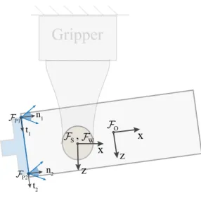
Figure 3-1 shows a schematic of a pushing scenario where an object in a grasp is pushed by a virtual pusher. Table 3.1 lists the notation used within the rest of the thesis.
Gripper
P1 P2 O S, W x z x z n1 t1 n2 t2Figure 3-1: Schematics of a prehensile pushing scene with important frames labeled.
𝑞 Configuration of the object ℱ𝑊 World frame, fixed to the gripper
ℱ𝑆
Support frame, fixed to the support surface. Located at the center of pressure at the contact
ℱ𝑂
Object frame, moving with the center of mass of the object
ℱ𝑃 𝑖
Pusher contact frame, moving with the i-th point contact modeling the pusher
𝑤support
Wrench exerted on the object by the support contact (in frame ℱ𝑂)
𝑤pusher
Wrench exerted on the object by the pusher contact (in frame ℱ𝑂)
𝑤s Wrench at the support contact (in frame ℱ𝑆)
𝑣𝑜𝑏𝑗 Object twist, i.e. generalized velocity, (in frame ℱ𝑂)
𝑣𝑠 Object twist at the support contact (in frame ℱ𝑆)
𝐽s Jacobian that maps𝑣𝑜𝑏𝑗 to𝑣𝑠
𝐽p= ⎡ ⎢ ⎣ 𝐽𝑃 1 𝐽𝑃 2 .. . ⎤ ⎥ ⎦
Jacobian that maps𝑣𝑜𝑏𝑗 to the velocity at the 𝑛
pusher point contacts in the pusher contact frames (ℱ𝑃 1, ℱ𝑃 2, ..)
Figure 3-2: Different contact geometries: point, line and planar, modeled as sets of rigidly connected 𝑘 points; vertex (𝑘 = 1), edge (𝑘 ≥ 2), face (𝑘 ≥ 3)
3.1.1
Coulomb Friction
Coulomb’s friction law is the basis for many of the models used to simulate frictional interaction between two rigid bodies. A Coulomb friction cone establishes the relationship between the normal force and the maximum friction force at a point contact.
We represent a point contact between two bodies by a local coordinate frame with, ˆ
𝑛 normal to the contact plane and and ˆ𝑡 and ˆ𝑜 spanning the contact plane. Let 𝑓 = [𝑓𝑛, 𝑓𝑡, 𝑓𝑜]⊤ and 𝑣 = [𝑣𝑛, 𝑣𝑡, 𝑣𝑜]⊤ be a net force and a relative velocity at a contact in the
local contact frame. For a given coefficient of friction (𝜇), the Coulomb friction cone at the contact is defined as the following set:
𝐹 𝐶 = {𝑓𝑛𝑛 + 𝑓ˆ 𝑡ˆ𝑡 + 𝑓𝑜𝑜 | 𝑓ˆ 𝑛≥ 0, 𝑓𝑡2+ 𝑓 2 𝑜 ≤ 𝜇𝑓
2
𝑛} (3.1)
By Coulomb’s law, when a contact slides, the contact force is on the boundary of the friction cone and the direction of the friction force is opposite to that of the sliding velocity at the contact. We can formalize this constraint using the standard complementarity and nonlinear equations[91, 97]: [(𝜇𝑓𝑛)2− 𝑓𝑡2− 𝑓 2 𝑜] ‖[𝑣𝑡, 𝑣𝑜]‖ = 0, (𝜇𝑓𝑛)2− 𝑓𝑡2 − 𝑓 2 𝑜 ≥ 0 (3.2) 𝜇𝑓𝑛𝑣𝑖+ 𝑓𝑖‖[𝑣𝑡, 𝑣𝑜]‖ = 0 𝑖 = 𝑡, 𝑜 (3.3)
Simple point contact models are usually favored because of computational convenience. However, they often fall short when reproducing physical contact realistically. A line or a planar contact kinematically constrains the set of relative motions between object and finger
more than a point contact does. Also, since the normal force can be distributed unevenly across the contact, it further affects the friction force distribution over the contact.
For the mechanics of general pushing manipulations developed in Section 3.2, we ap-proximate contact interactions of finite geometry as a set of rigidly-connected and evenly-distributed hard point contacts as shown in Figure 3-2. The relative velocities and the normal forces at the constituent contacts must be compatible with the fact that the points are rigidly attached to each other. For example, in the case of a rigid line contact, the knowledge of the velocities at two constituent contact points is sufficient to determine the velocity at any other point on the line. Similarly, in the case of a planar contact, three points determine the behavior of the entire patch. In general, for a contact of dimension 𝑚 (1-line, 2-planar), discretized into 𝑘 constituent points, we impose:
·
𝑘 friction cone constraints (3.2) and 𝑘 maximal dissipation constraints (3.3), one at each constituent contact, relating their respective forces and velocities.·
3𝑘 − 𝑚 − 4 independent constraints relating the velocities of the 𝑘 constituent points, to impose they move rigidly attached to each other. For example, for the case of a line contact (𝑚 = 1), given the velocities ⃗𝑣1, ⃗𝑣2 at two constituent points 𝑝1, 𝑝2, thevelocity ⃗𝑣𝑗 at any other constituent point 𝑝𝑗 must satisfy:
⃗
𝑣𝑗 = ⃗𝑣1+
⃗𝑣2 − ⃗𝑣1
dist(𝑝2, 𝑝1)
dist(𝑝𝑗, 𝑝1) (3.4)
yielding a total of 3(𝑘 −2) = 3𝑘 −6 constraints. We further impose that the velocities at points 𝑝1 and 𝑝2 have equal projection along the axis between them, making for a
total of 3𝑘 −5 constraints. For a planar contact, we similarly construct the constraints by linearly interpolating the velocities from three reference points.
·
The sum of the normal forces at all constituent contacts to be equal in magnitude to the expected normal force at the patch contact (for example, gripping force at finger contacts):∑︁
𝑗=1...𝑘
Fx Fz Ty P1 P2 O O Z X
Figure 3-3: (Left) The line pusher contact in this planar pushing example is modelled with two point contacts. The pusher contact frames and the object frame are drawn in the figure. The two-dimensional Coulomb friction cones at the point contacts are shown in the respective contact frames. (Right) The generalized friction cone of the line pusher provides the object frame representation of the set of forces the two point contacts can offer collectively. The the top and bottom facets of this cone are the generalized friction cones of the two point contacts modelling the line contact. Consequently, the convex hull of these two facets takes the form of a polyhedral cone with four facets and represents the generalized friction cone of the line pusher.
3.1.2
Generalized Friction Cone
Erdmann [29] introduced the concept of the generalized friction cone (𝑊 ) as the Coulomb friction cone at the contact expressed in the reference frame of the object. It is the wrench representation of the forces at the contact frame in the object frame. The generalized fric-tion cone for a line/patch contact modelled with multiple point contacts is the convex hull of the generalized friction cones for each constituent contact [28].
For the mechanics of planar pushing manipulations developed in Section 3.3, we model the friction between the pusher and the object by constructing the generalized friction cone:
𝑊pusher= {𝑤pusher=𝐽p⊤· 𝑓p | 𝑓p ∈ 𝐹 𝐶pusher} (3.6)
where, 𝐽⊤
p is the Jacobian that maps the contact forces𝑓pfrom the friction cone 𝐹 𝐶pusher
at the pusher point contacts to the object frame. Since the Coulomb friction cone rep-resents the set of feasible forces a point contact can offer, the generalized friction cone captures the set of feasible wrenches the pusher can impose on the object. For planar manipulations, a Coulomb friction cone at a point contact is a two-dimensional cone,
𝐹 𝐶 = {𝑓𝑛𝑛 + 𝑓ˆ 𝑡ˆ𝑡 | 𝑓𝑛 ≥ 0, ||𝑓𝑡|| ≤ 𝜇𝑓𝑛}. The generalized friction cone
representa-tion of this Coulomb cone is a planar facet (two-dimensional cone) in three dimensional wrench space. The generalized friction cone of a line contact modelled with two point con-tacts can be computed as a convex hull of the generalized friction cones of the two point contacts and takes the form of a polyhedral cone as shown in Figure 3-3.
If the contact between the pusher and the object is maintained (sticking), the pusher can impose any wrench on the interior of the generalized friction cone. However, if the object slips with respect to the pusher, the pusher wrench on the object will be on the boundary of the generalized friction cone.
3.1.3
Limit Surface
Goyal [36] defined the boundary of the set of all possible friction wrenches that a contact can offer as the Limit Surface. Each wrench on the boundary of the limit surface cor-responds to a different sliding motion of the object on the support plane. Based on the principal of maximum dissipation, the perpendicular to the limit surface at a given wrench provides the corresponding generalized velocity of the object [36].
The limit surface is smooth and convex if the support force distribution is finite every-where. Howe and Cutkosky [46], Xydas and Kao [99] showed that an ellipsoidal approxi-mation allows for a simpler representation of the limit surface geometry. In this thesis we will assume an ellipsoidal approximation of the limit surface, which has been shown to be computationally efficient for simulating and planning pushing motions [59, 25, 86, 101].
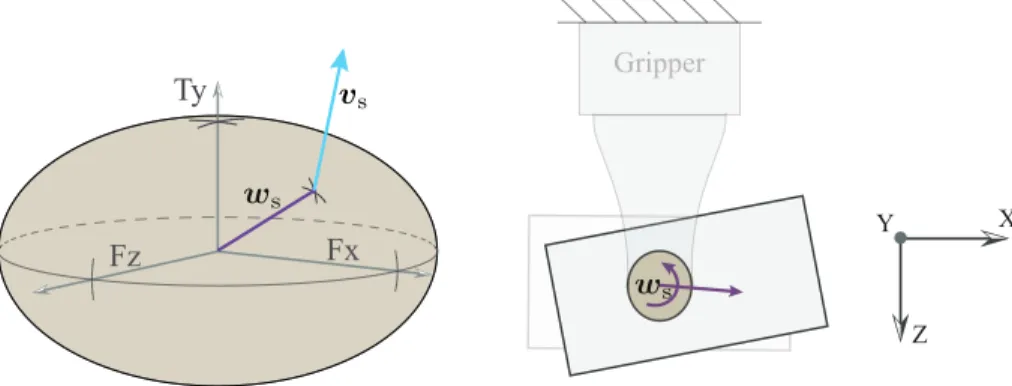
We use the limit surface to model the force-motion interaction between an object and a support contact when developing the mechanics of planar pushing manipulations in Sec-tion 3.3. In cases (a) and (b) in Figure 1-5, the surface on which the object rests is the support contact. In cases (c) and (d), the gripper fingers are the support contacts. As shown in Figure 3-4, for object motions in the manipulation plane, the resultant friction wrench 𝑤soffered by the support contact on the object is composed of the frictional forces (𝑓x, 𝑓z)
in the plane and the frictional torque (𝑚y) about the normal to the plane.
Fx Fz Ty Z X Y Gripper
Figure 3-4: (Left) Ellipsoidal approximation of the limit surface at the finger contact. For a wrench𝑤son the boundary of the limits surface, the twist at the contact𝑣sis normal to
the limit surface. (Right) The wrench𝑤sand the corresponding object motion is shown in
the manipulation scene.
in the support contact frame, ℱ𝑆. A mathematical representation of the ellipsoidal limit
surface is given by:
𝑤𝑇
s𝐴𝑤s = 1 (3.7)
where, for isotropic friction,
𝐴 = ⎡ ⎢ ⎢ ⎢ ⎣ 1 (𝜇s𝑁 )2 0 1 (𝜇s𝑁 )2 0 (𝑘𝜇1 s𝑁 )2 ⎤ ⎥ ⎥ ⎥ ⎦
such that 𝜇s is the friction coefficient between the contact and the object, 𝑁 is the
nor-mal force at the contact and 𝑘 is an integration constant. For a circular patch contact with a uniform pressure distribution at the contact, 𝑘 ≈ 0.6𝑟 where 𝑟 is the radius of the con-tact [99, 86]. Note that the geometry of the limit surface is defined by the area and pressure distribution at the contact and scaled by normal force and friction coefficient at the contact. When the object slides on the support contact, the friction wrench (𝑤s) at the contact
intersects the limit surface, as shown in Figure 3-4. The direction of object twist in the contact frame (𝑣s) is given by the normal to the limit surface at the intersection point [36]
and can be computed as:
𝑣s ∝
𝜕 𝜕𝑤s
(𝑤𝑇
Conversely, if the object twist at the contact (𝑣s) is known, we can find the friction wrench as, 𝑤s = 1 𝜆𝐴 −1 𝑣s (3.9)
Since𝑤slies on the ellipsoidal limit surface, from (3.7), we can solve for 𝜆:
(︁1 𝜆𝐴 −1 𝑣s )︁𝑇 𝐴(︁1 𝜆𝐴 −1 𝑣s )︁ = 1 𝑣s𝑇𝐴−𝑇𝐴𝐴−1𝑣s = 𝜆2 𝑣s𝑇𝐴−𝑇𝑣s = 𝜆2 √︁ 𝑣s𝑇𝐴−𝑇𝑣s = 𝜆.
Given that𝐴 is a diagonal matrix, 𝜆 =√︀𝑣s⊤𝐴−1𝑣s. Rewriting (3.9):
𝑤s= 𝐴−1𝑣s √︀ 𝑣s𝑇𝐴−1𝑣s = 𝜇s𝑁𝐵 −1 𝑣s √︀ 𝑣s𝑇𝐵−1𝑣s = 𝜇s𝑁𝑤s (3.10) Here, 𝐵 = 𝐷𝑖𝑎𝑔(1, 1, 𝑘−2) and 𝑤
s = [𝑓x, 𝑓z, 𝑚y]𝑇 is the wrench on a unit limit surface
(𝑤𝑇
s𝐵𝑤s= 1) which is scaled by 𝜇s𝑁 to produce the net frictional wrench𝑤s.
The force-motion mapping we have discussed so far is in the support contact frame. From (3.8) and (3.10), the direction of the object twist in the object frame (𝑣𝑜𝑏𝑗) for a given
wrench on the limit surface can be computed as:
𝑣𝑜𝑏𝑗 ∝ 𝐽s−1𝐵𝑤s (3.11)
where𝐽−1
s maps the object velocity from the support contact frame ℱ𝑆to the object frame
ℱ𝑂.
The fundamental principles of Coulomb friction and maximum energy dissipation serve as a basic for the contact models discussed earlier. In most basic yet general form, as in Section 3.1.1, they allow us to model force-motion relationships at a point contact or a set of point contacts simulating a complex geometry and irregular pressure distribution. These are most useful when reasoning about a valid force-motion solution at contact/s to explain instantaneous dynamics of a manipulation task as discussed in Section 3.2.
On the other hand, contact modelling constructs such as the the generalized friction cone and limit surface allow reasoning about a set of all possible wrenches contact/s can offer to explain the set of all possible dynamic solutions as discussed in Section 3.3. How-ever, these constructs are often computationally favorable only at relatively less complex scenarios such as planar manipulations or manipulations with uniform and unchanging pressure distribution.
3.2
Pushing Dynamics with Complementarity Constraints
Pushing can be seen as a case of a general rigid body problem where an object to be ma-nipulated is a passive movable body in contact with a passive fixed support surface and an active moving pusher. The dynamics of pushing then refers to modeling the force-motion relationship between active and passive bodies. Under such a general framework, the for-ward dynamics problem is solving for the motion of the object (passive body) in response to a motion of the pusher (active body), and the corresponding forces at all the contacts. The inverse dynamics problem refers to solving for the motion of the pusher (active body) re-quired to cause a desired motion of the object (passive body) and the corresponding forces at the contacts.
In this section, to capture the dynamics of a general prehensile pushing scenario in three dimensions, where contact interactions can be of complex geometry and pressure distribu-tion at them can be non-uniform, we adopt the contact modelling approach discussed in Section 3.1.1. Along with the contact constraints, kinematic and kinetic constraints for the pushing system form the basis for the dynamics formulation.
3.2.1
Modeling and Formulation
The fictional forces involved in prehensile pushing are much more dominant than the object inertia, so we will limit ourselves to a quasi-dynamic model of pushing. We define this model in the space of local contact forces, relative velocities at the contacts, velocity of the object, and velocity of the pusher. The solution space is constrained by the following kinematic and kinetic constraints.
Newton Euler Equation: The motion of a pushed object is in accordance with the net wrench acting on the object. As we are interested in a quasi-dynamic formulation, for a unit time step with zero initial velocity of the object, we can write the Newton’s law for an object with mass 𝑚 and generalized inertia matrix M as:
𝑤support+𝑤pusher+ 𝑚𝑔 = M · ⃗𝑣obj (3.12)
Here, (3.12) is written in the object frame located at the center of gravity. 𝑤support is the
friction wrench provided by the support contact,𝑤pusheris the wrench exerted by the pusher,
𝑚 is the mass of the object,𝑔 is the gravitational component in the plane of motion. Let 𝑓s be an array of local contact forces (𝑓s1, ..,𝑓sn) at points modelling the support contacts
and𝑓pbe an array collecting local contact forces (𝑓p1, ..,𝑓pn) at points modelling the pusher
contacts. The Jacobian𝐽⊤
s maps the support contact forces from the support contact frames
to the object frame. Similarly, the Jacobian 𝐽⊤
p maps the pusher contact forces from the
pusher contact frames to the object frame So,𝑤support =𝐽s⊤· 𝑓sand𝑤pusher=𝐽p⊤· 𝑓p, and
therefore (3.12) becomes:
𝐽s⊤· 𝑓s+𝐽p⊤ · 𝑓p+ 𝑚𝑔 = M · ⃗𝑣obj (3.13)
Rigid Body Motion Constraints: The local velocities at contacts are related to the veloc-ities of the object, hand, and pusher.
We can look at the motion of a contact point from two perspectives:
·
From the object point of view, the Jacobians𝐽sand𝐽prelate the velocity of the objectto the velocities at support and pusher contacts as𝐽s· ⃗𝑣objand𝐽p· ⃗𝑣obj respectively.
·
From the hand-pusher point of view, the hand actuation jacobian matrix𝐽act-srelatesthe velocities of the actuators in the gripper ˙𝜃sto the input velocities at finger contacts
as𝐽act-s· ˙𝜃s, and the pusher actuation jacobian matrix𝐽act-p relates the velocities of
the actuators in the gripper ˙𝜃pto the input velocities at pusher contacts as𝐽act-p· ˙𝜃p.
at all contacts, as difference between the input velocities and the reflection of the object velocity at those contacts points:
𝑉 = 𝑑𝑖𝑎𝑔(𝐽s,𝐽p) · ⃗𝑣obj− 𝑑𝑖𝑎𝑔(𝐽act-s,𝐽act-p) · [ ˙𝜃s, ˙𝜃p]⊤ (3.14)
Since we assume that the gripper is fixed in the world, ˙𝜃s = 0. Moreover, with our
ap-proach of virtual pushers, we have actuation directly at the pusher contacts, so the Jacobian 𝐽act-pis an identity matrix. Therefore (3.14) simplifies as:
𝑉 = [𝑣s,𝑣p]⊤ = [𝐽s· ⃗𝑣obj, 𝐽p· ⃗𝑣obj− ˙𝜃p]⊤ (3.15)
Unilateral Contact Constraints: There can not be interpenetration at contacts between two rigid bodies. Contacts can only push and not pull, and only when there in no separation at them. We write it as a complementarity constraint at each point contact.
𝑣𝑛· 𝑓𝑛= 0, 𝑣𝑛 ≥ 0, 𝑓𝑛≥ 0 (3.16)
Contact Modelling Constraints: We model the force-motion interactions at every contact as explained in Section 3.1.1. Equations (3.2) and (3.3) model the Coulomb friction cone and maximum energy dissipation principles with complementarity constraints. Further, for contacts with finite area modelled with arrays of point contacts, we impose constraints on the relative velocities at them to make sure that each array moves as a rigid contact patch as discussed in Section 3.1.1.
3.2.2
Numerical Solver for the Forward Dynamics Problem
The collection of all constraints discussed above define a solution space for pushing dynam-ics capturing the contact forces, contact velocities, pusher actuation velocities, and object velocity. The problem has the form of a nonlinear complementarity problem (NCP) with the additional linear constraints[97, 91]. This is commonly referred as mixed NCP (MNCP). We solve this MNCP as a nonlinear constrained optimization problem using interior point
method in MATLAB. We define the objective function as a sum of the complementarity constraints and minimize it subject to rest of the constraints. As each complementarity term is constrained to be non-negative, the minimum occurs when the objective function goes close to zero providing a feasible solution to the dynamics problem.
Now, with this dynamics formulation, for a given pusher motion, we can predict the motion of the object in the grasp and also the expected forces at the finger and pusher contacts. This is commonly known as the forward dynamics problem.
3.2.3
Experimental Validation
The dynamics formulation we developed in the previous section is an instantaneous model to solve for the pusher-object motion for a unit time step. To predict the motion of the object when pushed with a long continuous push, we iteratively solve the instantaneous forward dynamics problem in an explicit time-stepping fashion.
To evaluate the accuracy of our contact modelling and dynamics formulation, we exe-cuted prehensile pushes with different experimental settings of the grasping force, pushing speed, and pushing direction. We expect our dynamics model to be effective at reasoning about the contact interactions to first order. In practice, we see that prehensile pushing with multiple contacts with complex geometries is sufficient to expose the limitations of state-of-the-art contact modeling techniques. These manifest in the form of non-unique valid solutions and inaccurate predictions due to unmodeled compliance and manufacturing de-fects in the geometry and friction of the contact surfaces.
Experimental Setup
Figure 3-5 shows the setup we use to carry out the prehensile pushes. We use an industrial robotic arm and a force-controlled parallel-jaw gripper to grasp the objects and push them against the environment. We use a Vicon motion tracking system to capture the pose of the object. The fingertips of the gripper are instrumented with ATI Nano17 F/T sensors and the environment with an ATI Gamma F/T sensor. For improved accuracy, we run a basic calibration routine for all F/T sensors, to eliminate the intrinsic offsets if any.