HAL Id: tel-02136803
https://tel.archives-ouvertes.fr/tel-02136803
Submitted on 22 May 2019HAL is a multi-disciplinary open access archive for the deposit and dissemination of sci-entific research documents, whether they are pub-lished or not. The documents may come from teaching and research institutions in France or abroad, or from public or private research centers.
L’archive ouverte pluridisciplinaire HAL, est destinée au dépôt et à la diffusion de documents scientifiques de niveau recherche, publiés ou non, émanant des établissements d’enseignement et de recherche français ou étrangers, des laboratoires publics ou privés.
Lucas de Araujo Marques Leão
To cite this version:
Lucas de Araujo Marques Leão. Optimization of Communications in Multi-Sink Wireless Sensor Net-works. Electronics. Université Bourgogne Franche-Comté, 2018. English. �NNT : 2018UBFCD073�. �tel-02136803�
TH `ESE DE DOCTORAT DE L’ ´ETABLISSEMENT UNIVERSIT ´E BOURGOGNE FRANCHE-COMT ´E PR ´EPAR ´EE `A L’UNIVERSIT ´E DE FRANCHE-COMT ´E
´
Ecole doctorale n°37
Sciences Pour l’Ing ´enieur et Microtechniques
Doctorat d’Informatique
par
LUCAS AUGUSTO DE
ARAUJO
MARQUES
LE
AO˜
Optimization of Communications in Multi-Sink Wireless Sensor Networks
Th `ese pr ´esent ´ee et soutenue `a Besanc¸on, le 30 novembre 2018
Composition du Jury :
BOUMERDASSISELMA Maˆıtre de Conf ´erence HDR au CNAM Paris Rapporteur FLAUZACOLIVIER Professeur `a l’Universit ´e de
Reims-Champagne-Ardenne
Rapporteur HILTBENOIT Maˆıtre de Conf ´erence HDR `a l’Universit ´e de
Haute-Alsace
Examinateur PHILIPPELAURENT Professeur `a l’Universit ´e de Franche-Comt ´e Pr ´esident FELEAVIOLETA Maˆıtre de Conf ´erence `a l’Universit ´e de
Franche-Comt ´e
Co-directeur de th `ese GUYENNETHERVE´ Professeur `a l’Universit ´e de Franche-Comt ´e Directeur de th `ese
écol e doctoral e sciences pour l ’ingénieur et microtechniques
Universit ´e Bourgogne Franche-Comt ´e 32, avenue de l’Observatoire 25000 Besanon, France
Title: Optimization of Communications in Multi-Sink Wireless Sensor Networks
Keywords: wireless sensor networks, multiple sinks, routing, unicast, anycast, multicast, reliability,
longevity, timeliness, Contiki, COOJA, FIT IoT-LAB, WSN430
Abstract:
The design of a wireless sensor network may present numerous challenges, such as scalability, reliability, longevity and timeliness. The existence of multiple sinks may increase the network reliability and facilitates the scalability. However, this improvement is dependent on the routing approach, that must be tailored to help achieving the desired performance goals. From this perspective, the objective of this work is to find ways of optimizing the communication in multi-sink wireless sensor networks considering the problems related to scalability, longevity (network lifetime), reliability (packet delivery) and timeliness (latency). We
investigate the trades among data delivery time and energy consumption as key metrics for communication quality and efficiency. For that matter, we propose different routing algorithms, covering all three main communciations schemes (unicast, anycast and multicast). The executed simulations show that our approaches are capable of optimizing the communication, especially in terms of latency and network lifetime. Experiments on the FIT IoT-Lab platform also provide meaningful insights of the performance of our multicast solution in real environment conditions.
Titre : Optimization of Communications in Multi-Sink Wireless Sensor Networks
Mots-cl ´es : r ´eseaux de capteurs sans fil, multiples points de collecte, routage, unicast, anycast, multicast,
fiabilit ´e, dur ´ee de vie, latence, Contiki, COOJA, FIT IoT-LAB, WSN430
R ´esum ´e :
La conception d’un r ´eseau de capteurs sans fil peut pr ´esenter de nombreux d ´efis, tels que le passage `a l’ ´echelle, la fiabilit ´e, la long ´evit ´e et la latence. L’existence de plusieurs points de collecte peut augmenter la fiabilit ´e du r ´eseau et facilite le passage `a l’ ´echelle. Toutefois, cette am ´elioration d ´epend de l’approche de routage, qui doit ˆetre adapt ´ee pour atteindre les objectifs de performance souhait ´es. Dans cette optique, l’objectif de ce travail est de trouver des moyens pour optimiser la communication dans les r ´eseaux de capteurs sans fil `a multiples points de collecte en tenant compte des probl `emes li ´es au passage `a l’ ´echelle, `a la dur ´ee de vie du r ´eseau, `a la fiabilit ´e (livraison des paquets) et `a
la minimisation de la latence. Nous ´etudions les points d’ ´equilibre entre le d ´elai et la consommation d’ ´energie en tant que param `etres cl ´es pour la qualit ´e et l’efficacit ´e de la communication. Pour ce faire, nous proposons diff ´erents algorithmes de routage, couvrant les trois principaux sch ´emas de communication (unicast, anycast et multicast). Les simulations effectu ´ees montrent que nos approches sont capables d’optimiser la communication, notamment en termes de latence et de dur ´ee de vie du r ´eseau. Des exp ´eriences sur la plateforme FIT IoT-Lab fournissent ´egalement des indications significatives sur les performances de notre solution multicast dans des conditions r ´eelles.
A
CKNOWLEDGMENTS
I express here my gratitude to...
My dear supervisors, in particular to Dr. Herv ´e Guyennet, who patiently passed on his knowledge and guidance during this process of growth. And especially to my co-supervisor Dr. Violeta Felea for the patience, the support, the unconditional dedication, the great expertise and absolute care during the development of this work.
Dr. Selma Boumerdassi and Dr. Olivier Flauzac, for their willingness in revising and commenting on my work. And the members of the jury, Dr. Benoit Hilt and Dr. Laurent Philippe for accepting our invitation to be part of this evaluation committee.
The DISC department and the doctoral school SPIM for the financial support in confer-ences and workshops.
The Brazilian National Council for Scientific and Technological Development (CNPq) for the scholarship that made this work possible.
The staff from the M ´esocentre de calcul de Franche-Comt ´e for all the support.
Maxime, Vincent, Paola, Zhouyang, Yiwei, Qianqian for the great help during the simula-tions and experiments.
The DISC department staff, for the absolute help with all the paper work and equipment. The french people in general for receiving me so well and so warmly.
My dear department colleagues, PhD students and interns, for the support and for the good time every Wednesday.
My dear friends, always present in my life, supporting and encouraging all my dreams and giving me the strength to move on and overcome each obstacle. Especially to Mauricio for the extra incentives, for believing me, and for standing by me. To Ivelize for the amazing talks and memorable trips. To Vania, Lilian, Beatriz, Edgar, Andr ´e and Leticia for the friendship. To Bruna, who was my guardian angel when I first arrived in Besac¸on. To Kizzyy, Lemia and Lydia, for being amazing and friendly. To Florent and Lisa, for the many good moments, the support and friendship. To Thomas and Sophie, for the fun play. And of course to my amazing friend, work colleague, french teacher, psychologist, confident and so on, Karla - you made my life much easier here.
Finally, to my parents Alberto and Elisabete, to whom I owe my life, for the infinite support, for being sensitive and understanding, and for standing by me. And to my brothers Andr ´e and Pedro, who helped me become who I am. You all are my safe haven and my source of energy. We are stronger as a family, and no physical distance can destroy this.
C
ONTENTS
Introduction 1
I Multi-sink wireless sensor networks 7
1 Wireless sensor networks 9
1.1 Network composition . . . 9
1.2 Topology structure . . . 10
1.3 Layered model . . . 12
1.4 Application type . . . 14
2 Multi-sink wireless sensor networks 15 2.1 Processing type . . . 15
2.2 Communication schemes . . . 16
2.2.1 Application perspective . . . 17
2.2.2 Routing perspective . . . 17
2.3 Implementation objectives . . . 20
II State of the art on multi-sink wireless sensor networks solutions 21 3 Routing solutions in MS-WSN 23 3.1 Classification of routing solutions . . . 23
3.2 Routing solutions description . . . 26
3.2.1 Unicast . . . 26 3.2.1.1 Single-path . . . 26 3.2.1.2 Multi-path . . . 28 3.2.2 1-Anycast . . . 31 3.2.3 k-Anycast . . . 33 3.2.4 Multicast . . . 34 3.3 Conclusion . . . 35 vii
4 Other solutions in MS-WSN 37 4.1 MAC solutions in MS-WSN . . . 37 4.1.1 Classification . . . 38 4.1.2 Description . . . 38 4.2 Application-level solutions in MS-WSN . . . 39 4.2.1 Classification . . . 39 4.2.2 Description . . . 40 4.2.2.1 Sink coordination . . . 40
4.2.2.2 Sink quantification and placement . . . 40
4.2.2.3 Sink placement . . . 41 4.3 Conclusion . . . 42 5 System validation 45 5.1 Theoretical analysis . . . 45 5.2 Simulations . . . 46 5.2.1 Network size . . . 47 5.2.2 Simulation tools . . . 47 5.3 Real-life experiments . . . 50 6 Conclusion 51 III Contributions 53 Motivation for our contributions 55 7 Unicast 57 7.1 Motivation . . . 58
7.1.1 System model and assumptions . . . 58
7.1.2 DD protocol . . . 59
7.1.2.1 Initial tree construction . . . 59
7.1.2.2 Tree reconstruction . . . 60
7.2 Dynamic Back-off in DD (DB-DD) . . . 61
7.2.1 Preventive response . . . 61
7.2.2 Dynamic back-off time . . . 62
7.2.3 Operation . . . 63
CONTENTS ix
7.3 DB-DD with buffer constraint . . . 69
7.3.1 DB-DD with Fixed Buffer Constraint (DB-DD-FBC) . . . 71
7.3.1.1 Operation . . . 71
7.3.1.2 Results . . . 72
7.3.2 DB-DD with Dynamic Buffer Constraint (DB-DD-DBC) . . . 74
7.3.2.1 Operation . . . 74
7.3.2.2 Results . . . 75
7.4 Conclusion . . . 78
8 Anycast 79 8.1 Motivation . . . 80
8.1.1 System model and assumptions . . . 81
8.1.2 KanGuRou . . . 82
8.2 Geographic K-anycast routing (GeoK) . . . 84
8.2.1 Preprocessing . . . 85
8.2.2 Candidates filtering . . . 85
8.2.3 Forwarders selection . . . 87
8.2.4 Sink distribution . . . 90
8.2.5 Routing . . . 91
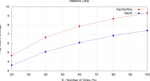
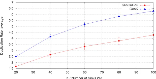
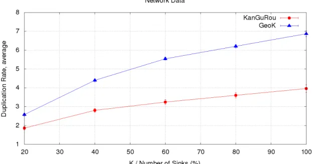
8.3 Simulation and results . . . 92
8.3.1 Fixed number of sensors and sinks . . . 93
8.3.1.1 Networks without void areas . . . 93
8.3.1.2 Networks with void areas . . . 97
8.3.2 Variable number of sensors and proportional number of sinks . . . . 100
8.3.2.1 Networks without void areas . . . 100
8.3.2.2 Networks with void areas . . . 101
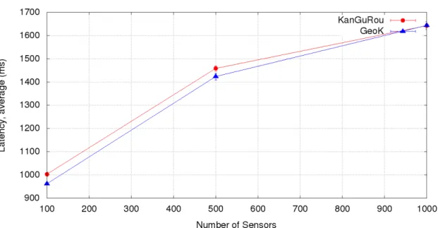
8.3.3 Variable number of sensors and fixed number of sinks . . . 103
8.4 Conclusion . . . 106
9 Multicast 107 9.1 Motivation . . . 108
9.1.1 System model and assumptions . . . 108
9.1.2 k-Anycast comparison . . . 109
9.2 Geographic Multicast routing (GeoM) . . . 109
9.2.1 Filtering process . . . 110
9.3 Simulation and results . . . 116
9.3.1 Variable number of sensors and proportional number of sinks . . . . 117
9.3.1.1 Networks without void areas . . . 117
9.3.1.2 Networks with void areas . . . 120
9.3.2 Variable number of sensors and fixed number of sinks . . . 122
9.3.3 Comparison of GeoM with GeoK . . . 124
9.4 Conclusion . . . 127
10 Real-life experiment 129 10.1 Motivation . . . 129
10.2 Code porting and experimental platform description . . . 130
10.2.1 Code adaptation . . . 130 10.2.2 Experiment launching . . . 131 10.3 Execution . . . 134 10.3.1 Real-life results . . . 134 10.3.1.1 Short run . . . 136 10.3.1.2 Long run . . . 139 10.3.2 Simulation results . . . 141 10.4 Conclusion . . . 145 Conclusion 147 Bibliography 151 List of Figures 166 List of Tables 168 IV Annexes 169 A Network generation 171 A.1 Network deployment . . . 171
A.2 Random deployments for simulation . . . 172
A.2.1 Completely random deployments . . . 174
A.2.2 Random-grid deployments . . . 176
A.3 Comparison: real-life and simulated deployment . . . 178
CONTENTS xi
B GeoK performance 181
B.1 Latency: 50 to 250 sensor nodes . . . 181 B.2 Maximum energy consumption: 50 to 250 sensor nodes . . . 183
C GeoM performance 187
C.1 Maximum energy consumption over time: 50 to 250 sensor nodes . . . 187 C.2 Nodes distribution in terms of energy consumption: 50 to 250 sensor nodes 189
I
NTRODUCTION
G
ENERALC
ONTEXTThere are many definitions for Wireless Sensor Networks (WSN), but the most frequent descriptions point to a joint characterization of hardware and software. The WSN is de-fined as a group of small electronic devices with limited processing resources, energy, and radio range, organized as an ad-hoc wireless network, tasked with monitoring or tracking activities.
Research in wireless sensor networks has been a hot topic for many years now. Many advances in WSN have been proposed with numerous researches being carried out in different domains [1]. The continuous development of the WSN solutions is directly asso-ciated to the evolution of correlated technologies (microelectronics, sensory, communica-tions, etc.) along with the combination of WSN with other research areas. For instance, the work in [2] points out WSN as an enabling technology for the IoT (Internet of Things). It means that the development and evolution of IoT applications may also trigger interest-ing researches in WSN.
In some application fields there is a large perimeter to be monitored, as for example in Smart Cities, oriented to intelligent buildings, where sensors are deployed in every apartment to monitor metrics as water, energy consumption or other different interesting metrics. All these information are collected and transferred to a central node, meant to compute statistical consumption information, thus allowing adaptation of energy or water flow. The deployment of a WSN to monitor such application would lead to the existence of hundreds to thousands of sensor nodes, with scalability featuring as a key aspect of the implementation [3].
In this context, one way to tackle the scalability problem is to consider the deployment of multiple sinks. The scalability must be managed because of two reasons: congestion and increased path length. In single sink networks, all the traffic is directed to one point. The existence of several sinks allows a better distribution of the traffic, helping to increase the network lifetime.
When the area of deployment increases, using the same sensor technology for the com-munication range, longer path lengths from nodes to single sinks are generated. Adding extra sinks causes the average length of a routing path to decrease, because geographic distances between nodes and sinks are smaller. Consequently, packet latency and en-ergy consumption are also decreased as benefit of a shorter path length. Moreover, reliability of communications is improved. Especially when packets are addressed to mul-tiple sinks, generating a beneficial redundancy, which helps to guarantee the delivery of the packets. In theses cases, the number of packets increases and the routing strategy must be adapted in order to cope with the new demand.
In this work we focus on the optimization of the communication in terms of data delivery
time and network lifetime, using the existence of multiple sinks as a precondition to the optimization strategy. We also focus on the differences and challenges that multiple sinks introduce at the routing level.
R
ESEARCHP
ROBLEMOne important communication optimization objective is the increase of the network life-time, with solutions trying to reduce the energy consumption through numerous strate-gies. Another relevant objective is related to the time sensitive communication, with solu-tions trying to reduce the transmission delays in order to reduce the overall latency. When these two optimizations are associated, a conflict is created. That is because strategies to extend the network lifetime may also lead to an increase of the overall latency. In that sense, finding a point of balance between the two objectives becomes a challenge. According to [4] the design and implementation of WSN may have many challenges, including the scalability problem. A large WSN may be impracticable considering the existence of a single sink. The amount of data gathered by the nodes and forwarded to the sink may overload the network capacity, increasing the latency, and leading the nodes in the sink neighborhood to an early depletion of the energy. Therefore, Multi-Sink WSN (MS-WSN) is presented as an important solution for a large group of challenges (scalability, reliability, real-time communication, network lifetime optimization). Neverthe-less, [4] states that the class of routing protocols traditionally applied to single sink WSN may not cope with the complexities and particularities associated to the multiple sinks WSN. Depending on the application demand, packets may be forwarded to one specific sink, to any of the sinks, or even to all sinks. In that sense, it is possible to list different communication schemes for WSN with multiple sinks. From a routing perspective, we may list three communication schemes: unicast, anycast and multicast. For each one of the communication schemes, the routing protocol must be tailored to achieve the desired goals.
The optimization of the communication at the level of the routing protocol for WSN having multiple sinks depends on the communication scheme. The optimization strategy applied to a unicast routing protocol can not be directly applied to a multicast approach. In a unicast solution the packets are forwarded to a single sink among all sinks, the solution strategy may consider selecting the path to the sink node presenting the best network metrics. However, when the packet has to be sent to all sinks, the strategy changes and the selected paths may also consider balancing the load, distributing the packets through different paths or merging paths to a group of sinks.
Most of the existing solutions for multi-sink wireless sensor networks consider the packet delivery to only one sink among the group of sinks. The strategies vary between unicast and 1-anycast communication schemes. These are good strategies for the scalability problem and latency optimization, but they are not as adequate to problems involving reliability. In that sense, increasing the number of destination sinks also increases the reliability, since the packet is duplicated and sent to different sinks.
We can summarize the challenges in three groups: the design of a routing protocol sidering the existence of multiple sinks; the implementation of a solution strategies con-sidering the reliability problem; and the optimization of the communication in terms of data delivery time and network lifetime.
3
O
BJECTIVES ANDC
ONTRIBUTIONSThe main objective of our work is to find ways of optimizing the communication in multi-sink wireless sensor networks. We address three main issues of the WSN: longevity (network lifetime), reliability (packet delivery) and timeliness (latency). We investigate the trades among data delivery time and energy consumption as key metrics for com-munication quality and efficiency. We also focus our efforts on studying the specificity connected to the existence of multiple sinks in a wireless sensor network. For that mat-ter, we propose three strategies for packet routing considering different communication schemes (unicast, anycast and multicast). The routing decisions take into account the particularities of each communication scheme in order to optimize the network.
Our contributions include three different solutions, considering each of the communication schemes and optimizations on data delivery time and energy consumption. We detail the evaluation of the approaches using both simulation and experimentation. Furthermore, we propose a classification criteria for the solutions on multiple sink wireless sensor net-works based on the communication scheme and the solution type. We present the char-acteristics and particularities of MS-WSN solutions, along with a discussion on some research opportunities in the field of multiple sinks WSN.
The first solution is a unicast approach, focused on reducing the packet latency by means of a MAC-aware strategy that considers the transmission delay as a decision metric for the routing path. In this solution, we work on the aspect of the packet forwarding to specific sinks and the reuse of routes for future transmissions as an attempt to predict the final latency and to provide packet delivery under a predefined deadline. Due to the need of timeliness communication, congestion and buffer size are also considered important metrics, leading us to the definition of a buffer control strategy.
For the second approach we proposed a k-anycast protocol. The k-anycast class of solution is extremely flexible. It may behavior as 1-anycast when k = 1 or even as a multicast approach when k= |S |, with S representing the set of all sinks. In our solution, we are focused on increasing the network reliability by means of forwarding the packets to k sinks. We also focus on reducing the network latency and increasing the network lifetime. Our strategy considers the aggregation of network metrics as a decision process for the next hop. It is a distributed solution that requires low network knowledge and that assures the packet forwarding to exactly k different sinks.
In the third solution we proposed a multicast protocol that is as well capable of reducing the network latency and increase the network lifetime. The objectives were at one hand to provide a solution capable of delivering packets to all sinks as a way to increase the reliability and the information availability, and at the other hand to verify the particularities of the multicast communication scheme as a counterpoint to the k-anycast with k = |S |. We show that it is possible to take advantage of the knowledge that packets must be de-livered to all sinks to improve the routing decision and achieve better latency and network lifetime.
All solutions were validated with simulations and compared to other existing solutions. Our unicast solution was validated using a homemade simulator in SciLab [5]. Both k-anycast and multicast solutions were implemented on top of the Contiki operating system [6] and validated through simulations using the COOJA network simulator. The simulation computations were performed on the supercomputer facilities of the M ´esocentre de calcul de Franche-Comt ´e. Additionally, we provide real-life results for our multicast solution and
another existing protocol. Both solutions were tested on the FIT IoT-LAB testbed [7]. We demonstrate not only the behavior of our solution in real conditions, but also its correlation to the simulation results.
T
HESISP
LANThis document is divided in three parts. The first part is dedicated to the definition of Wireless Sensor Networks composed of both single sink and multiple sinks. The second part is dedicated to the state of the art in MS-WSN. In the third part we present our solutions and the final considerations in the conclusion.
The Chapters composing the first part are:
• Chapter 1 Wireless Sensor Networks - in this chapter we introduce the basic concepts of wireless sensor networks.
• Chapter 2: Multi-Sink Wireless Sensor Networks - here we present the particu-larities related to the existence of multiples sinks in a WSN.
The Chapters composing the second part are:
• Chapter 3: Routing solutions in MS-WSN - in this chapter we present a clas-sification for the routing solutions designed for multi-sink WSN, along with a brief description of each solution.
• Chapter 4: Other solutions in MS-WSN - here we enumerate and describe the existing solutions considering multi-sink WSN at the MAC and application level.
• Chapter 5: System Validation - in this chapter we survey the validation methods applied on the described solutions.
• Chapter 6: Conclusion - here we present a summary of the second part and some research opportunities in MS-WSN.
The Chapters composing the contribution part are:
• Chapter 7: Unicast - here we describe our first solution, dealing with the opti-mization of the data delivery time, in a cross-layer fashion and using the unicast communication scheme.
• Chapter 8: Anycast - in this chapter we present our second solution, focused on the reliability and the trade-off between data delivery time and network lifetime, using a k-anycast communication scheme.
• Chapter 9: Multicast - in this chapter we present our third solution, also focused on reliability and data delivery time versus network lifetime, but using a multicast communication scheme.
• Chapter 10: Real-Life experiment - here we present the details related to the validation of our multicast solution in a real-life environment.
5
We conclude this document with the conclusion chapter, where we present the final ar-guments, the perspectives and work opportunities.
The source code of the implemented approaches are available at: https://gitlab.com/lucas.augusto/geo multi-sink
I
M
ULTI
-
SINK WIRELESS SENSOR NETWORKS
1
W
IRELESS SENSOR NETWORKS
Contents
1.1 Network composition . . . . 9 1.2 Topology structure . . . . 10 1.3 Layered model . . . . 12 1.4 Application type . . . . 14
Wireless Sensor Network (WSN) rises rich research topics that have been deeply ex-plored. It is the platform option for numerous applications, such as building management systems, healthcare monitoring systems, military and environment surveillance, and an enabling technology for the Internet of Things. A wireless sensor network can be defined as a network composed of small electronic devices, with limited processing and energy capacity, capable of performing sensory tasks, and exchange messages through wireless medium in order to feed a central entity - the sink - with sensory data.
1.1/
N
ETWORK COMPOSITIONA WSN is, in general terms, composed of two distinct entities: the sink and the sensor node. The number of sinks and sensor nodes may vary according to the application, and there may be wireless sensor networks with several sinks and sensor nodes, as exemplified in Figure 1.1.
(a) Single sink (b) Multiple sinks Figure 1.1: Single sink and Multi-sink Wireless Sensor Networks
The sink acts as a gateway to the sensor nodes, collecting and centralizing the monitored information. The sink may be connected to another network, for example an IP network with Internet access, and acts as an interface between the WSN and the external net-work, where the data is routed and processed. Communications between nodes is done via radio, with the sink receiving data packets from each sensor node. The number of de-ployed sinks varies according to the application objectives, network structure and system architecture [8]. Applications of Smart Cities to monitor electricity consumption in house-holds, for example, may require that several sinks are deployed, covering a given region, and centralizing information for packaging and shipping to a processing plant through an external network. Generally, it is expected from the sinks a better processing capacity and greater autonomy compared to the other sensor nodes.
A WSN may be composed of hundreds of sensor nodes, working collaboratively to mon-itor one or more characteristics of the environment. The sensor nodes are, in general, limited devices, with strong restrictions regarding communication range, memory and pro-cessing. Sensor nodes can communicate with each other or only with the sink depending on the application and the network structure. In this way, it is necessary to establish the rules controlling the forwarding process, and the routing protocol is responsible for that task. With the proper routing protocol, the data packets can be correctly forwarded through the network towards the destination [9].
1.2/
T
OPOLOGY STRUCTUREAccording to [8], WSN can be classified based on the network architecture. The deploy-ment may follow different topologies, such as:
• Point-to-Point: Sensor nodes communicate with the sink through a chain of sen-sors. The sensor node sends a packet to its neighbor node, and the packet is forwarded from node to node until the destination is reached, as shown in Figure 1.2. The advantage of this strategy is the simplicity of implementation, however, it is unreliable, since any failure in the path prevents the final target to be reached. The packet is forwarded in a multihop manner the sink node.
Figure 1.2: Point-to-point topology
• Point-to-Multipoint: Sensor nodes communicate directly with the sink. The sink is able to send packets to each of the sensor nodes, as shown in Figure 1.3. However, the sensor nodes can not communicate directly with the other nodes of the network. The advantage of this strategy is linked to energy savings, since there is no need for more sensor nodes to get involved in the routing chain. However, the size of the network is limited to the radio range of the sink and sensor nodes.
1.2. TOPOLOGY STRUCTURE 11
Figure 1.3: Point-to-multipoint topology
• Mesh network: The sensor nodes are able to communicate with the sink or any other sensor node in the network directly as long as they are within the radio range, as seen in Figure 1.4. This type of network presents a better fault tolerance, since the network generally remains functional even after a sensor node failure. However, the implementation becomes more complex and the challenge for energy savings is even greater.
Figure 1.4: Mesh topology
• Hybrid network: The sensor nodes communicate with the sink directly or via an-other sensor node. In this configuration, we may have different routing structures, such as clusters and completely ad-hoc (graph-based). In clustering, a sensor node acts as a group leader, taking the responsibility of routing packets between several sensor nodes and the sink. In hierarchical, sensor nodes may follow a tree-based structure, with a node acting as a root and other nodes organized in the form of par-ent nodes and child nodes, as shown in Figure 1.5. In ad-hoc, the sensor nodes are vertices of a graph, with communication links being represented by edges between vertices. The hybrid network topology allows the combination of Point-to-multipoint and Mesh network, increasing fault tolerance, reducing energy consumption and enabling the implementation of high density networks. However, the routing proto-col becomes more complex.
Figure 1.5: Hybrid topology
1.3/
L
AYERED MODELWSN are typically structured in a five layer stack: Application, Transport, Network, Data Link and Physical [10], as shown in Figure 1.6. In the layered model, the information is processed at one layer and moved to the adjacent layer for further processing, following a strict communication interface. Each layer has a specific responsibility and acts on a particular metric within the scope of this responsibility. This way, the layered model provides modularity and flexibility, allowing different couplings of protocols for each layer.
Figure 1.6: Layered model
In this structure, each layer plays a specific role:
• Application Layer: responsible for the monitored information, providing services according to the type of application;
• Transport Layer: responsible for controlling the communication flow;
• Network Layer: responsible for the packet forwarding, with the addressing and path definition;
• Data Link Layer: responsible for controlling the medium access and the energy management (duty cycle);
• Physical Layer: responsible for the radio signal modulation, channel and transmis-sion power.
1.3. LAYERED MODEL 13
According to [11] strategies to optimize the communication in wireless sensor networks that follow the traditional layered model may achieve their purposes when strictly analyzed by the metrics of each individual layer. This means that although a particular problem is well addressed in a specific layer, the overall network performance does not benefit from a global optimization. For that reason, it is suggested that wireless sensor networks should be designed in a cross-layer fashion, allowing significant improvements in different network metrics. However, it is important to ensure that the gains with the cross-layer design pay off the loss of modularity inherent from this type of strategy.
Within a cross-layer strategy, layers share information in an integrated way, allowing de-cisions from one layer to be influenced by information from another layer. Cross-layer approaches may be divided in two major groups: inter-layer and intra-merged-layers. In the first, the well-known layered composition is maintained, but interactions within adja-cent and non-adjaadja-cent layers are developed so protocol decisions at one layer are based on the decisions taken by the protocols from other layers in a back-and-forward way. The second category stands for a different approach. All layers or a group of layers are combined in order to create a single super layer able to respond for the functions of the merged layers.
• Inter-layer: The decisions in one layer are based on the information extracted from another layer (Figure 1.7). As for instance, a MAC solution on the data link layer may use the information of the routing tree from the network layer in order to optimize the slot scheduling and reduce the latency [12, 13, 14, 15, 16, 17]. That would be a MAC protocol based on routing. The same way, the routing protocol would use the information of the slot scheduling shared by the MAC in order to build an optimized routing tree that also reduces the network latency [18, 19]. This approach can be described as routing based on MAC. And in a third option, both routing and MAC could interact in an enchained way in order to achieve better performance in terms of routing and scheduling [20, 21, 22], finally leading to a routing and MAC back-and-forth cross-layer solution.
Figure 1.7: Inter-layer representation
• Intra-merged-layers: Merging of adjacent layers. A common (or super) layer taking simultaneous decisions, as for example, MAC and routing decision are done at the same time (Figure 1.8). A solution may be designed in a way that the route is created at the same time as the slot allocation takes place, for TDMA-based solutions. Instead of basing the allocation of slots on a predefined route, or create the routes based on an existing slot schedule, the decisions of next hop and slot allocation are taken simultaneously.
1.4/
A
PPLICATION TYPEAccording to [9], WSN applications can be classified into two categories: tracking and monitoring.
• Tracking: this type of solutions are related to applications which purpose is to iden-tify objects, animals or people in certain locations. For example, a solution for track-ing objects in a house can use sensor nodes scattered in all rooms to detect objects. Objects must be properly identified with RFID tags so that they can be located. The application issues the command for object tracking, and the sensor nodes next to the tagged object identify it, informing the central application of the location where the RFID label of the object was detected.
• Monitoring: they are characterized by the monitoring of phenomena, characteris-tics or events. Monitoring applications can be related to the monitoring of natural events, such as rainfall, seismic and volcanic activities, as well as characteristics of closed environments, such as temperature, ventilation, luminosity, smoke detection, energy consumption, etc. Monitoring applications can also be classified in terms of information criticality and time sensitiveness. Real-time applications require robust monitoring solutions with fault tolerance and redundancy. Differently, low criticality data monitoring solutions may not require fault tolerance mechanisms, since the loss of a data does not compromise the overall functioning of the system.
2
M
ULTI
-
SINK WIRELESS SENSOR
NETWORKS
Contents 2.1 Processing type . . . . 15 2.2 Communication schemes . . . . 16 2.2.1 Application perspective . . . 17 2.2.2 Routing perspective . . . 17 2.3 Implementation objectives . . . . 20The Multi-Sink Wireless Sensor Network (MS-WSN) is a particular case of the WSN containing multiple sinks. Compared to single sink solutions, the use of several sinks normally leads to better network performance. On top of that, it also improves the network manageability, providing more flexibility and continuity [23]. By increasing the number of sinks, the number of hops a packet has to travel before reaching any of the sinks should normally decrease. It has a direct impact on the performance of metrics such as network lifetime, energy balance, latency, congestion, etc.
Solutions considering multiple sinks are designed over a number of different criteria. The decisions taken at the implementation level must account for the objectives to be achieved and the limitations imposed by the chosen solution strategy. Thus, it is relevant to point out the particularities associated to the existence of multiple sinks in WSN.
2.1/
P
ROCESSING TYPEIn general, WSN applications and protocols may work in a centralized or distributed way. A centralized algorithm for the routing protocol may find a global optimum solution faster than a distributed one. However, the level of knowledge on the network topology is far more elevated for centralized approaches than for distributed solutions, and in MS-WSN the coordination among sinks may increase the complexity in both cases (centralized and distributed processing).
• Centralized: in centralized solutions the decisions are taken in a central entity based on the fact that the central entity has a higher knowledge of the network state in comparison to other network entities. In the case of WSN, the sink is nor-mally the central entity. However, in MS-WSN, since there are more than one sink,
the decisions in a centralized solution may be taken in three different ways: a) at each sink with the information being shared among them. It is still considered a centralized solution because the network information is centered at the sinks, and they coordinate together as a single entity; b) at a central processing entity which gathers the information from each sink through a wired connection or another re-liable link; b) at each sink independently, since each sink is considered to be the central entity of a sub-WSN.
• Distributed: in distributed solutions the decisions are taken at the sensor nodes in two different ways. Either it is independently, when the sensor nodes dispose of enough information to take decisions, or collaboratively, when they are able to gather the necessary data to support the decision process. As for instance, in geographic routing, the sensor nodes may possess information of their geographic location and that from their 1-hop neighbors and sinks; this way the sensor node may decide to forward the packet to the neighbor node that offers the best progress in terms of distance to the closest sink.
• Hybrid: in hybrid solutions the decision process may happen in many different ways. As for example, at first a non-optimal routing may be created in a distributed way and once the central entity gathers the necessary information, an optimal route is created. Another option is to create an initial route in a centralized way, with the routes maintenance happening in a distributed way, with nodes exchanging data and deciding for new forwarders to reach the sink. The applied technique depends on the application demand and on the final objective. The common aspect is that the decision process is neither entirely taken centrally nor sparsely.
2.2/
C
OMMUNICATION SCHEMESThe final application drives the way communication takes place. The information is re-trieved following different models in order to cope with the application objectives and requirements. For instance, in order to meet a specific requirement such as reliability, the communication can follow a many-to-many scheme, meaning that sensor nodes send their data to a number of destinations, which can be a set of sinks or all sinks in the net-work. At the application perspective, the important aspect is the number of destinations and if the destination target is predefined or not.
The routing protocol must obey the requirements imposed by the application. It means that if the application requires a many-to-many communication type, the routing protocol must be capable of forwarding the packet to a number of sinks in the network. However, the communication scheme may be described in a different way at the routing level. The problem of reaching all sinks in the network may be solved by multiple implementation strategies considering different communication schemes, such as unicast and multicast communication schemes. At the routing perspective, the forwarding mechanism is the most important aspect.
Therefore, we identify a twofold view of the communication schemes: at the application level and at the routing level.
2.2. COMMUNICATION SCHEMES 17
2.2.1/ APPLICATION PERSPECTIVE
Many-to-one
• Predefined target: one particular sink must be reached depending on the informa-tion type. An applicainforma-tion monitoring three different parameters can be implemented in a way that each parameter must be sent to a specific sink. The nodes share the same environment and responsibilities (sensing and forwarding data), but informa-tion is forwarded to different destinainforma-tions according to the applicainforma-tion’s objective. That may be the case of a Building Management System, with sensors monitoring luminosity and temperature. The information about the environment lightening may be relevant only to a specific sink, which will also manage the actuators that will increase or decrease the lightening.
• Undefined target: one of the sinks must be reached, but no specific sink is ad-dressed. A system seeking better performance in both latency and energy con-sumption may require any sink to be able to receive the data, leaving the destina-tion decision to the routing strategy. This way the network is able to achieve longer lifetime and reasonable latency. An example is a fire detection system in a forest. The network must be active for as long as possible, but once an event is detected, the data must be delivered in a reasonable time, to any of the sinks available.
Many-to-many
• Predefined target: a number of specific sinks in the network must be reached. The information is forwarded and replicated until it reaches all predefined sinks. Generally, it is related to specific application demands, such as reliability and data availability. This is particularly interesting for a system requiring the sensed infor-mation to be available at all sinks, and where sinks are not interconnected through an external network. A system tracking buses in a city may require the information of the actual position of the bus to be available on every bus stop, so users will be informed about the waiting time.
• Undefined target: a group of sinks must be reached. The information must be repli-cated and forwarded to a number of sinks. But the final destinations are not defined. The need to reach multiple sinks may be connected to a reliability requirement. As an example, in a Healthcare Monitoring System, a sensor network monitoring pa-tients may forward the sensed data to one of the sinks in a normal situation, but in case of an emergency, the information may be forwarded to several sinks in order to make sure the event will be acknowledged.
2.2.2/ ROUTING PERSPECTIVE
• Unicast: the information is addressed to one sink and it is not changed during the forwarding process. The sink selection may be predefined by the application or decided based on the routing structure. Figure 2.1 illustrates the composition.
Figure 2.1: Information from sourcen is addressed to sink A
• Anycast: information is addressed to any of the sinks, so the destination may change during the forwarding process. It can be 1-anycast, when information is forwarded to any sink in the group, or k-anycast when information must reach any k sinks, as illustrated in Figure 2.2. The anycast communication scheme may be applied to either increase network reliability (k sinks) or extend the network lifetime (any one sink).
(a) 1-anycast: any sink must be reached (b) k-anycast: k= 2 sinks must be reached Figure 2.2: Information from sourcen is addressed to any of the sinks A, B and C
• Multicast: information is addressed to a number of sinks. It may be all the sinks in the network or a number of predefined sinks. The destination sinks are defined at the source node, and the destinations are not changed during the forwarding process. The information of a single sensor node is replicated and forwarded to each one of the predefined sinks, as shown in Figure 2.3. Multicast approaches are focused on network reliability and information availability.
Figure 2.3: Information from sourcen is addressed to all sinks A, B, or C
The communication strategy at the application perspective can be implemented using different strategies of the communication scheme at the routing perspective. Table 2.1
2.2. COMMUNICATION SCHEMES 19
illustrates how each of the communication strategies of the application perspective can be designed at the routing perspective.
Table 2.1: Application vs Routing implementation strategies
Application perspective Comm. scheme Target Routing perspec. Implementation strategy Many-to-one
Predefined Unicast The packet is forwarded to one specific sink. The destination is defined at source.
Undefined
Unicast
The packet is forwarded to one specific sink. The destination is defined at source as part of the routing strategy (disjoint spanning trees rooted at each sink).
1-Anycast
The packet is forwarded to any of the sinks. The final destination is decided during the forwarding process.
Many-to-many
Predefined
Unicast
The packet is replicated at source and each packet is forwarded to a different sink. The destinations are defined at source.
Multicast
The packet is forwarded to a group of spe-cific sinks. The destinations are defined at source. The duplication of the packet takes place during the forwarding process.
k-Anycast
We consider S the set of all sinks. It only works if the k value represents the set of all predefined sinks (S0), which means that
k = |S0| and S0 ⊆ S. In this case, S0 is the set of destination sinks. Otherwise, it is not possible to assure that a specific sink re-ceives the packet. The packet duplication takes place during the forwarding process.
Undefined
Unicast
The destinations are defined at source as part of the routing strategy (spanning trees rooted at each sensor node with the sinks as leaf nodes). The packet is replicated at source and forwarded to one specific sink.
1-Anycast
The packet is replicated at source and each packet is forwarded to any of the sinks. The final destination is decided during the for-warding process. It is difficult to assure that different sinks receive the packet.
k-Anycast
The packet is forwarded to a group of sinks. The final destinations are decided during the forwarding process, along with the du-plication of the packet. In this case, it is possible to assure that k different sinks re-ceive the packet.
2.3/
I
MPLEMENTATION OBJECTIVESMost of the time the performance objectives of a WSN are driven by the application de-mands. The solutions are designed in a way to accomplish the imposed requirements. The performance objectives of a WSN may include different targets varying from energy optimization to real-time communications. However, the simple design of a WSN with several sinks is not enough to achieve the desired performance. For that reason, solu-tions in MS-WSN must be tailored using different metrics in order to reach the needed objective.
• Longevity: the main goal is to prolong the network lifetime. The lifetime of a net-work can be described in different ways, such as the first node to die, the last node to die and the moment when the network becomes disconnected. It depends on the requirements defined by the application. In all cases, many factors may in-fluence the network lifetime, such as the occurrence of collisions, congestion and re-transmissions, the unbalanced traffic and energy consumption, the paths with excessive amount of hops, etc. Since WSN are normally composed of devices with limited energy capacity, the longevity of the network is crucial. According to [24], in MS-WSN the distance traveled by a packet is reduced since the possibility of a node to be close to a sink is higher, consequently reducing the overall consumed energy. However, specific techniques must be applied to organize the packet trans-mission and routes, as well as to define the sink positioning in order to profit from the existence of multiple sinks.
• Reliability: data availability and network resilience are the two main aspects of the reliability. The focus is to assure that data will be available for the application when necessary. For that purpose, other metrics are considered during the solu-tion implementasolu-tion, such as redundancy of nodes and/or paths, the packet delivery rate, collisions, congestion, energy consumption etc. The reliability class of solu-tions covers approaches centered on techniques such as fault tolerance, multi-path, packet duplication etc.
• Timeliness: this main objective is related to the techniques for communication opti-mization seeking the miniopti-mization of the end-to-end delay. Applications with specific deadlines for message delivery require the solutions to take into account metrics such as queue delay, transmission delay, latency, collisions, congestion, hop count and other metrics that have influence on the delivery time. Normally, it is the main objective of low latency applications, but many solutions consider the metrics re-lated to timeliness as secondary optimization objectives.
II
S
TATE OF THE ART ON MULTI
-
SINK WIRELESS
SENSOR NETWORKS SOLUTIONS
3
R
OUTING SOLUTIONS IN
MS-WSN
Contents
3.1 Classification of routing solutions . . . . 23 3.2 Routing solutions description . . . . 26
3.2.1 Unicast . . . 26 3.2.2 1-Anycast . . . 31 3.2.3 k-Anycast . . . 33 3.2.4 Multicast . . . 34
3.3 Conclusion . . . . 35
In general, a routing solution is an implementation of a set of responsibilities connected to the network layer in the OSI model. The main task of a routing solution is that of the discovery of routes towards a destination. In Multi-Sink WSN this task must account to the fact that multiple sinks are available, and therefore multiple routes should be considered. Moreover, depending on the application’s objective, the communication scheme is such that the routing solution must find a path to one sink (unicast), to any of the sinks (1-anycast), to a set of any of the sinks (k-(1-anycast), or even to all target sinks (multicast). The routing strategy becomes more complicated when compared to single sink solutions, and many particularities arise, such as the necessity of duplicating packets (for k-anycast and multicast).
Our classification criteria for Multi-Sink WSN routing approaches are presented in Section 3.1 followed by a synthesis of each solution in Section 3.2. In Section 3.3 we present a brief conclusion with the main characteristics of the routing solutions in MS-WSN.
3.1/
C
LASSIFICATION OF ROUTING SOLUTIONSWe focus the classification of the MS-WSN routing solutions on the multi-sink aspect. The objective is to present the particularities raised by the existence of multiple sinks. The solutions are classified through five different categories: communication scheme, path strategy, sink decision, route structure and packet duplication, as presented in Table 3.1.
The routing perspective of the Communication Scheme (already detailed in Subsection 2.2.2) focuses on bringing evidence to how the multi-sink aspect was considered in the solutions in terms of packet destination.
Comm. Scheme Path Strategy Sink Decision Route Structure Packet Duplic. References
Unicast Single path Fixed Tree No [25][26][27][28][29]
[30][31][32][33][34]
Unicast Multi-path At source Tree No [35][36][37][38]
Unicast Multi-path At source Graph No [39][40][41][42]
Unicast Multi-path At source Tree/Graph No [43][44]
1-Anycast Multi-path On the way Graph No [45][46][47][48][49]
[50][51][52][53]
k-Anycast Multi-path On the way Tree Source [54]
k-Anycast Multi-path On the way Graph Source [55]
k-Anycast Multi-path On the way Graph On the way [56] Multicast Multi-path Fixed Tree/Graph On the way [57][58]
Table 3.1: Summary of routing solutions in MS-WSN
The Path Strategy indicates the robustness of the solution in terms of connectivity. It is more likely for a multi-path solution to sustain the network connectivity for a longer time than a solution that considers a single path strategy. Although the concept of multiple paths and single path is also found in single sink WSN, the definition of multi-path and single path changes slightly in multi-sink WSN:
• Single path: the node is connected to a single sink through a single path. Despite the fact that the network is enabled with multiple sinks, nodes are part of a single disjoint tree rooted at one sink.
• Multi-path: there are essentially two different cases. The first is when the node is connected to multiple sinks through different trees or routes. It is considered multi-path because the packet can be forwarded to a sink through more than one multi-path; in this case each path leads to a different sink. The second case is when the packet can be forwarded through multiple paths to the same sink. We may find both cases in the same solution when the communication scheme is anycast.
The Sink Decision identifies the moment the destination sink is chosen. Since in Multi-Sink WSN there is more than one sink able to receive the packet, a decision of which sink will effectively receive the packet needs to be taken. It depends on the communication scheme and also on the path strategy.
• Fixed: the destination is fixed and predefined. The destination may be imposed by the routing structure, as for the case of disjoint trees rooted at each sink, or an application requirement. The packet must be delivered to the predefined sink, and there is no change in the destination during the forwarding.
• At source: the sinks are decided at the source node, before the first hop. The source node is connected to more than one sink and according to specific metrics, the choice for a sink is made and respected through the entire forwarding task. • On the way: the sink decision is taken on the way instead of at the source node.
3.1. CLASSIFICATION OF ROUTING SOLUTIONS 25
used metrics. This way, any of the sinks may be reached, depending on the network state in terms of the used metrics.
The Route Structure intends to show how the paths are organized. Similarly to single sink WSN, we may have tree or graph structures. However, there are some particularities to these structures when applied to Multi-Sink WSN.
• Tree: there are three different cases of tree structures in MS-WSN. The first is the case of disjoint spanning trees rooted at each sink and having sensor nodes composing the structure in an exclusive way. It means that a node is part of only one tree. The second case considers almost the same scenario as the first case, with multiple trees rooted at each sink, but with all sensor nodes being part of all trees. Finally, the third case considers trees rooted at the source nodes with each of the sinks as leaf nodes.
• Graph: with the graph structure it is considered that the network paths can assume any form. For instance, it can be a DAG (Directed Acyclic Graph), a graph based on geographic distance to any sink, or even a graph based on the nodes sched-ule/availability at a given moment. The graph structure is the most used strategy for Multi-Sink WSN running with anycast, since it gives much more options in terms of paths to reach any of the sinks.
• Tree/Graph: it considers a tree structure that at a certain level can also have graph characteristics. For example, a tree with a graph structure at the level of the leaf nodes, or among the sink neighbors. Also at the borders of different trees so that they can be inter-connected by a bridge node. We consider the DODAG (Destination-Oriented Directed Acyclic Graph) to be a Tree/Graph structure.
The Packet Duplication is an underlying characteristic of MS-WSN running with k-anycast (k > 1) and multicast. Since the data must be forwarded to k sinks for the case of k-anycast or to all sinks for the case of multicast, the packet must be duplicated at a given moment. The decision of when the packet is duplicated is highly connected to the sink decision, but not entirely determined by it.
• At source: the packet is duplicated at source. If k sinks must be reached, exactly k transmissions of the same packet will be made. There are two possible addressing options. Either the packet takes the exact address of the sink to be reached or a set of potential addresses. The set of addresses are disjoint from one packet to another. For instance, if some data must be delivered to k sinks, with k = 2, and the network is covered by 4 sinks, the first packet may have the destination sink set {1, 2} and the second packet the set {3, 4}. So, the first packet may be delivered to any sink in the set {1, 2} and the second packet to any sink in the set {3, 4}. With this strategy, the algorithm works as k-anycast during the duplication, and as 1-anycast during the forwarding process after the set of sinks is defined.
• On the way: the packet is duplicated during the forwarding task. The duplication moment happens at the same time as the occurrence of a fork in the forwarding path. The need of a fork in the forwarding path is caused by the existence of dis-joint paths towards the addressed sinks in relation to the current node. Initially,
the packet travels without duplication through a single path. Then, because of the disjoint paths, the packet must be duplicated and sent towards different directions. This is the case of a hard duplication, when two or more packets are created and forwarded. However, another possible case is when the packet is not effectively duplicated, but sequentially forwarded. The packet has a number of sinks to be reached and it decrements this value each time it encounters a sink.
3.2/
R
OUTING SOLUTIONS DESCRIPTIONIn this section we present a brief description of the routing approaches considering multi-ple sinks. We divide the presentation of the solution based on their characteristics, mainly in regard to the applied technique in terms of communication scheme.
3.2.1/ UNICAST
We present the unicast solutions divided in two groups: multi-path and single-path. As already described in Subsection 2.2.2, in unicast communication scheme the packet is forwarded to one single sink and the destination does not change during the forwarding.
3.2.1.1/ SINGLE-PATH
In the class of solutions categorized in the single-path group, there is only one path ex-ploited towards the destination sink. The routing structure is formed by disjoint trees, and each node participates in only one tree.
Solution [25] defines a data collection scheme that satisfies a specific end-to-end delay constraint, where nodes send collected data to a single sink with the lowest latency in a multiple-sink network. Using a heuristic algorithm and in a centralized way, the latency is evaluated for each node towards each sink and the path with the lowest latency is se-lected. Load balance is also considered in latency estimation in order to avoid excessive collisions, which consequently increases the latency. Disjoint trees are constructed with the sinks as roots. The nodes join the trees in a greedy way, checking the hop-count of the neighbor nodes to the closest sink. After that, the information is evaluated by the centralized algorithm and the tree is changed in order to satisfy the desired latency constraint.
In [26] the objective is to reduce the energy consumption, to balance the sink flows and to prolong the network lifetime, by means of pre-clustering and clustering techniques, considering both energy and location information in a dynamic metric that changes over time. The algorithm creates different regions in the network in order to create a pre-cluster. The sinks broadcast messages with different power ranges creating different circles representing areas of coverage. Then, within each ring, the clustering process takes place considering the nodes distance to the center of the ring, the distance to the sink, the average energy of the nodes in the cluster and the residual energy. The packets are forwarded to the cluster head that later forwards them to the cluster head of the next ring. The path to the sink is selected in a way that minimizes the relative distance to the sink. The cluster heads are changed after the execution of each round, in order to better
3.2. ROUTING SOLUTIONS DESCRIPTION 27
distribute the energy consumption. The sinks calculate the distance and angle of each cluster area and broadcast the information to all nodes, this way the nodes know to which cluster they belong. The cluster heads are chosen based on the decision metrics, and they vary according to the network stage. If it is the first round, only the distance from the node to the cluster center and the distance from the node to the sink are considered. For the other rounds, the average energy of nodes within the cluster and the residual energy are as well considered. In addition, the metrics take different weights in the decision process. The weights are dynamically regulated during the network lifetime, in order to give more importance to the energy factor in the late cycles of the process. Moreover, the relative position of clusters are adjusted every round in order to avoid nodes far away from the cluster center to deplete energy faster.
In [27] the authors define a data collection scheme with minimum latency. The routes are based on the transmission schedule. Two strategies are presented: ’LP-based’ builds a time-expanded graph showing all possible links at each time and from there defining the schedule. And ’greedy BFS-based’ that creates layers of sensors based on the hop-count to sinks and scheduling the transmission based on the proximity to the sink, also considering the interference of neighbor nodes.
In [28] the objective is to balance the network load, avoid the early depletion of the neigh-bor nodes of the sinks and increase the network lifetime. Using a mobile anchor to delimit zones in the network, the algorithm dynamically changes the size of the zones based on the network load and residual energy of the hotspot sensor nodes. The routing is defined within a region by considering the PSF function (Path Selection Factor) which evaluates the proportion between the residual energy and the node distance to the hotspot neigh-bor.
In [29] the objective is to define a communication protocol able to adjust the network load by distributing the nodes within different spanning trees. It creates initial spanning trees based on the shortest path and other routing metrics in case of multiple options. It evaluates the load distribution for each sink and determines the need of a balancing phase, while advertising the ideal load in each cluster. The nodes decide to switch from one cluster to another in a distributed way, based on the switching threshold.
In [30] the objective is to extend network lifetime as well as to assure the feasibility of the routing proposal. The strategy is based on the definition of a MAC-aware data aggrega-tion strategy which directly affects the routing feasibility (path is selected among nodes that fulfill the conditions). The routing is defined by an Integer Linear Programming (ILP) solution based on flow balance, energy consumption and medium availability to forward packets to a specific sink.
In [31] the objective is to improve the energy-consumption in order to increase the network lifetime in WSN with secondary sink nodes. It creates a hierarchy based on the remaining energy. Level-1 nodes must receive and forward packets, and Level-2 nodes only forward packets. Nodes must keep the information from neighbor sensors. The routing protocol is similar to the LEACH [59] way of working, since it defines a hierarchy to organize the network. The hierarchy is constructed based on the residual energy. The packets are forwarded to higher levels of the hierarchy until reaching the sink. The secondary sink to be reached is defined by the tree structure, based on the residual energy of the nodes. Once the packet is received by one of the secondary sink nodes, it is again forwarded to the primary sink. With this strategy, the multiple sinks are organized as secondary sinks with the primary sink as the root.
In [32] the objective is to define a binding strategy based on a genetic algorithm where nodes select the optimal sink to forward the data, considering the hop distance to the sinks. The central processing entity gathers all the network information and starts a process of binding nodes to the optimal sink, respecting rules defined at the genetic algorithm level. The nodes are separated into different categories and the binding process happens respecting the order defined with the categories. The algorithm starts with an initial phase of network discovery. Then, a second phase takes place in a central station, where the nodes are bound to a sink. This process is iterative, starting with nodes 1-hop away from the sink (first exclusive nodes, then non exclusive nodes). Later, the other nodes are bound to a sink based on their neighbors already connected to a sink. At the last phase, the algorithm informs the other nodes of the defined tree.
In [33] the objective is to maximize the network lifetime in a multi-source multi-sink WSN. The basic strategy is to identify the path that maximizes the network lifetime by selecting the pair (source, node) which has the greatest lifetime among the ones with the lowest life-time. The authors present two solutions, one centralized (LOCL) and another distributed (LONL). Both algorithms work as a stepwise process that builds trees rooted at each sink, searching for the configuration that maximizes the network lifetime.
In [34] the objective is to balance the network load by creating multiple spanning trees, distributing the traffic evenly within the branches, and to minimize the total latency by reducing the maximum hop count. The process of building the trees is centralized and considers the amount of traffic generated by nodes as well as the amount of neighbors. Once the initial trees are constructed, the algorithm reevaluates each branch and ex-ecutes inter-branch adjustments to better distribute the traffic and then an intra-branch adjustment, to minimize the latency by reducing the maximum hop count. The span-ning multi-tree construction starts by identifying the sink neighbors, called sink-adjacent nodes. The sink-adjacent nodes are inserted in the expandable branch list, if they have unattached nodes in their vicinity. Then, each branch is expanded by attaching a neighbor node to it from the list of unattached nodes.
3.2.1.2/ MULTI-PATH
For the solutions categorized in the multi-path group, the packet is forwarded through different paths, but the destination sink remains the same. We divide the solutions into tree-based, graph-based and tree/graph-based approaches.
Tree-based: in tree-based approaches, the route structure is composed of spanning trees rooted at each sink, with sensor nodes participating in multiple trees. Once a des-tination sink is defined, the packet is forwarded upwards in the tree rooted at the chosen sink.
In [35] the objective is to define a collection algorithm focused on improving the network lifetime and reliability, by means of proposing multiple trees rooted at each sink as alter-native routes in case of node failure or energy depletion, in order to extend the network lifetime and balance the energy consumption. The trees are built based on the link cost and the cumulative path cost. Hop count, residual energy and neighbor distance are the metrics considered for the link cost. The nodes join a tree in a greedy way based on the cumulative cost. The sink decision is taken at the source node, before the first hop, when the path is selected and followed up to the destination. There is a periodic update of the trees, in order to keep the path cost updated in respect to the residual energy.