HAL Id: tel-02136213
https://tel.archives-ouvertes.fr/tel-02136213
Submitted on 21 May 2019HAL is a multi-disciplinary open access archive for the deposit and dissemination of sci-entific research documents, whether they are pub-lished or not. The documents may come from teaching and research institutions in France or abroad, or from public or private research centers.
L’archive ouverte pluridisciplinaire HAL, est destinée au dépôt et à la diffusion de documents scientifiques de niveau recherche, publiés ou non, émanant des établissements d’enseignement et de recherche français ou étrangers, des laboratoires publics ou privés.
smart composite structures
Xianlong Chen
To cite this version:
Xianlong Chen. Development of a low-cost in-situ material characterization method and experimental studies of smart composite structures. Other. Université Bourgogne Franche-Comté, 2019. English. �NNT : 2019UBFCA002�. �tel-02136213�
i
THÈSE présentée par
Xianlong CHEN
pour obtenir le
Grade de Docteur de
l’Université de Technologie de Belfort-Montbéliard
Spécialité : Sciences pour l’ingénieur
Development of a low-cost in-situ material characterization method
and experimental studies of smart composite structures
Soutenue le 12 Mars 2019 devant le Jury :
Prof. Niels Modler
Rapporteur
Technische Universität Dresden
Prof. Zoheir Aboura
Professeur des universités
Rapporteur
Université de Technologie de
Compiègne
Dr. Manuel Collet
Directeur de chercheur, CNRS
Examinateur
Ecole Centrale de Lyon
Prof. Morvan Ouisse
Professeur des universités
Directeur de thèse
Univ. Bourgogne
Franche-Comté, ENSMM
Dr. Yann Meyer
Maître de Conférences, HDR
Co-directeur de
thèse
Univ. Bourgogne
Franche-Comté, UTBM
Dr. Rémy Lachat
Enseignant-chercheur
Co-encadrant de
thèse
Univ. Bourgogne
Franche-Comté, UTBM
iii ACKNOWLEDGEMENTS
First and the most importantly, I would like to express my sincere gratitude to my supervisor Dr. Yann Meyer for the continuous support of my Ph.D study and related research, for his patience, motivation, and immense knowledge. Even in my daily life, I’ve got lots of help and advices from him, I could not have imagined having a better advisor and mentor for my Ph.D life.
Besides, I would like to thank Prof. Morvan Ouisse, for his brilliant and illuminating instructions on my research and insightful comments for my papers and thesis. Also, I would like to thank Dr. Rémy Lachat, for his suggestions and help on the manufacturing of composite structures.
I would like to thank Prof. Niels Modler and Prof. Zoheir Aboura, for their illuminating comments in their reports for my thesis, which help me a lot to improve my thesis. Also, I would like to express my gratitude to Dr. Manuel Collet and Prof. Martin Dannemann, for their presence to my defense and their brilliant comments and questions.
I want to express my deep gratitude to all my friends, thank you for the happy time we spent together and the memories that we have shared over the past few years. Without you, I cannot imagine how boring my life will be. And I am also very grateful to all my colleagues, for their kindness help in my work.
I would further like to give my gratitude to the financial support from the program of China Scholarships Council (CSC) (201504490012).
A very special word of thanks goes for my parents, thanks for their constant love and support. The last word goes for the love of my life, Pauline Kim, thanks for her company and her love.
Xianlong CHEN Belfort, 2018
v
RÉSUMÉ
Les structures composites intégrant des transducteurs piézoélectriques au cœur de la matière sont utilisées pour leur capacité à modifier leurs propriétés mécaniques en fonction de l’environnement, à contrôler leur intégrité structurale et à interagir avec l’homme ou avec d’autres structures.
Ce travail se concentre sur les phases de conception préliminaire des structures composites intelligentes. Ces phases ne représentent que 5% du coût total d’un projet, mais conditionnent 80% du coût final du produit. Les principaux problèmes rencontrés lors de ces phases de conception préliminaire portent sur la détermination des propriétés matériau des transducteurs piézoélectriques et des matériaux composites utilisés, de l'influence de l'emplacement des transducteurs dans la structure ainsi que de l’influence du processus de fabrication, de la température et des endommagements sur le comportement final des structures composites intelligentes.
Dans le processus de fabrication développé à l’Université de Technologies Belfort-Montbéliard (UTBM), l’élément-clé est un produit semi-fini appelé “soft layer”. Cette couche permet d’intégrer le réseau de transducteurs piézoélectriques au cœur de la structure composite. Le processus de fabrication de la “soft layer” ainsi que celui des
structures intelligentes sont abordés dans cette thèse.
Afin de trouver des solutions aux problèmes décrits ci-dessus, deux méthodes de caractérisation de composites intelligents ou adaptatifs sont présentées et utilisées : la méthode dite Resonalyser et la méthode du temps de vol. Après des études expérimentales et une comparaison des résultats obtenus, la méthode du temps de vol a été choisie comme méthode principale en raison de son faible coût de mise en œuvre et du fait qu’il s’agit d’une méthode de caractérisation in-situ. De plus, une nouvelle méthode
appelée méthode CMB, basée sur la méthode du temps de vol a été développée afin de pouvoir facilement et rapidement extraire les constantes élastiques, en particulier le coefficient de Poisson.
Des analyses expérimentales de sensibilité appliquées aux composites adaptatifs ont été effectuées.
Premièrement, l’étude de l’influence de l’emplacement des transducteurs démontre qu’il est nécessaire de tenir compte de la position de la “soft layer” dans la modélisation du comportement de produit final. La position de cette couche dans l’épaisseur du produit a une influence notable sur les fréquences propres ainsi que les amplitudes modales de la structure. Cependant, l’ajout de la “soft layer” n’accroît pas le taux d’amortissement de la structure finale; et sa position dans l’épaisseur n’a aucune influence sur ce taux d’amortissement. La propagation des ondes de Lamb à l’intérieur du composite n’est pas impactée par le “soft layer”.
Deuxièmement, l’étude de l’impact du processus de la fabrication nous renseigne sur l’influence notable des divers paramètres de réglage du processus de fabrication sur le comportement final de la structure composite intelligente.
Troisièmement, l’étude de l’influence de la température sur des structures constituées de différents matériaux composites montre que le module de Young du produit final décroît quand la température augmente. Mais la diminution du module de Young en fonction de la température est différente selon les et les types de matériaux et les directions des fibres, en particulier pour les structures composites unidirectionnelles. De plus, cette étude montre également la sensibilité de la méthode du temps de vol vis-à-vis de la température. Ce dernier point est par ailleurs consolidé par la comparaison avec des résultats obtenus par une méthode de caractérisation ex-situ standard : l'analyse dynamique de la mécanique (DMA).
Enfin, l'étude de l'impact des dommages mécaniques fournit une assez bonne référence pour les recherches futures. De cette façon, il est clair qu’une méthode de temps de vol peut être utilisée dans la surveillance de la santé structurale.
De plus, certaines structures composites intelligentes fabriquées par l'équipe sont présentées et leurs applications potentielles sont discutées.
vii
Mot clés: Composites à base de polymères, Structures composites intelligentes,
Méthode de caractérisation in-situ, Méthode Low-cost, Mesure du temps de vol, Ondes de lamb, Contrôle non destructif, Implant piézoélectrique, "soft layer", Capteurs intégrés
ix
ABSTRACT
The composite structures embedding piezoelectric implants are developed due to their abilities of modifying mechanical properties according to the environment, of keeping their integrity, of interacting with human beings or with other structures.
This study is focused on the preliminary design stages of smart composite structures, which represent only 5% of the total costs of a project, whereas 80% of the life cycle cost are set during the preliminary study phases. The top few problems during the preliminary design of smart composite structures are addressed in this work such as the determination of the material properties of the piezoelectric transducers and composite material used, the influence of transducers location, manufacturing process, temperature and damage on the behavior of the smart composite structures.
Due to the manufacturing process developed at the Université de Technologie de Belfort-Montbéliard (UTBM), the most important element is a semi-finished product called “soft layer”. This special layer is used to embed the transducers system into the composite structures. The manufacturing process of “soft layer” as well as the smart composite structures are compiled in this report.
In order to solve the problems described above, two characterization methods of composite material (Resonalyser method and Time-of-Flight method (T-o-F method)), are introduced and discussed. After experimental studies and comparing the results of these two methods, the T-o-F method is chosen as the main method for the following studies due to the fact that it is a low-cost and in-situ characterization method. Furthermore, a new method based on the T-o-F method is developed to easily and quickly extract the elastic constants, in particular the Poisson’s ratio.
Experimental sensitivity analyses applied to the smart composite structures are performed with respect to the problems describes above. First of all, the study of the influence of transducers location demonstrates that the "soft layer” cannot be neglected to model the behavior of the final product. In particular, the through-the-thickness position has an influence on the eigenfrequencies and the modal amplitudes. However, the "soft
layer” does not increase the overall damping ratio of the final structures and the through-the-thickness position of the "soft layer” has no influence on the damping ratios. The Lamb wave propagation inside the composite material is not impacted by the "soft layer”. Secondly, the study of the impact of manufacturing process demonstrates that the impact of variability of parameters due to the manufacturing process is very important on the final response of the structure. Thirdly, the study of the influence of temperature on different kinds of smart composite structures proves that when temperature increases, the Young’s modulus of the smart composites decreases. But the attenuation of Young’s modulus according to temperature is different along different fiber directions, especially for the unidirectional composite structures. Furthermore, in this study, the sensitivity of Time-of-Flight method with respect to temperature is well proved by comparing the results with a traditional method like Dynamic-Mechanical Analysis (DMA). Last but not least, the study of the impact of the mechanical damage gives a quite good reference for the future investigations. Along this way, it is possible to use a Time-of-Flight method in Structural Health Monitoring. In addition, some smart composite structures manufactured by the research team are given and their potential applications are discussed.
Key words: Polymer-based composites, Smart composite structures, In-situ
characterization method, Low-cost method, Time-of-Flight measurement, Lamb waves, Non-destructive testing, Piezoelectric implant, “soft layer”, Embedded sensors
xi
CONTENTS
CHAPTER 1. Introduction ...1
CHAPTER 2. Smart Composites ...21
2.1 Soft Layer ...22
2.2 Manufacturing Process ...25
2.3 Examples of manufactured products ...27
2.4 Conclusions ...33
CHAPTER 3. Material Characterization ...35
3.1 Characterization of Piezoelectric Transducers ...35
3.2 Characterization of Composite Materials...37
3.2.1 Resonalyser Method ... 37
3.2.2 Time-of-Flight (T-o-F) Method ... 40
3.2.3 Comparison between Resonalyser Method and T-o-F Method ... 46
3.2.4 Concluding Remarks ... 50
3.3 A New Method for Poisson’s Ratio Measurement ...51
3.3.1 Introduction ... 51
3.3.2 Theoretical Background ... 51
3.3.3 Description & Validation of the CMB Method ... 55
3.3.4 Application to Composite Structures ... 58
3.3.5 Concluding Remarks ... 59
3.4 Conclusions ...59
CHAPTER 4. Experimental Sensitivity Analyses ...61
4.1 Influence of the Transducers Location ...61
4.1.1 Smart Composite Beams: Description & Manufacturing ... 64
4.1.2 Experimental Characterization Method ... 66
4.1.3 Experimental Results and Discussion ... 72
4.1.4 Conclusions ... 78
4.2 Impact of Manufacturing Process ...78
4.2.1 Description of the Smart Composite Spherical Cap ... 79
4.2.2 Experimental Analysis ... 79
4.2.3 Numerical Analysis ... 81
4.3 Influence of Temperature vs different composite materials ...84
4.3.1 Smart Composite Test Plates ... 85
4.3.2 Assumption of Poisson’s ratio ... 87
4.3.3 Experimental Process ... 88
4.3.4 Experimental Results ... 90
4.3.5 Conclusions ... 105
4.4 Impact of Damages ...105
4.4.1 Experiment Design ... 106
4.4.2 Results & Discussions ... 107
4.4.3 Conclusions ... 114
CHAPTER 5. Conclusions and Future Works ...117
Appendix A Manufacturing Process of Smart Composite Structures ...121
xiii LIST OF TABLES
Tab 1-1 Geometries and dimensions of embedded piezoelectric transducers in the
literature ... 7
Tab 3-1 Parameters of interest from the measured data [54] ... 36
Tab 3-2 Experimental values and standard deviations of ... 49
Tab 3-3 Material parameters extracted with the Resonalyser method ... 50
Tab 4-1 Location of the piezoelectric transducers for each beam reference ... 66
Tab 4-2 Initial (I) and corrected (C) data for each beam reference from (a) to (c) ... 70
Tab 4-3 Initial (I) and corrected (C) data for each beam reference from (d) to (f) ... 71
Tab 4-4 Corrected experimental eigenfrequencies for each beam reference and the maximal standard deviation for each natural vibration frequencies ... 73
Tab 4-5 Maximum amplitudes for each beam reference and for each natural mode.... 75
Tab 4-6 Modal damping ratios for each beam reference ... 75
Tab 4-7 Time-of-Flight values for each beam reference ... 77
Tab 4-8 Comparison of the experimental natural frequencies, the numerical ones from the Resonalyser method and the numerical ones from the Time-of-Flight method ... 82
Tab 4-9 Details for each smart composite plate ... 86
Tab 4-10 Details for fiber ply of each smart composite plate ... 86
Tab 4-11 Young’s modulus along each wave direction at room temperature (GPa) .... 92
Tab 4-12 Top temperature limit for each path of each smart composite (°C) ... 95
xiv LIST OF FIGURES
Fig 1-1 One possible classification of smart materials [6] ... 2
Fig 1-2 Architecture of a smart composite structure [8] ... 3
Fig 1-3 The basic five components of a smart structure [9] ... 4
Fig 1-4 Fiber forms at different scales [20] ... 5
Fig 1-5 Manufacturing techniques for active structures with integrated piezoelectric elements [40]... 8
Fig 1-6 The cross-section of a completely embedded bulk piezoelectric element without a cut-out [40] ... 11
Fig 1-7 The cross-section of a completely embedded bulk piezoelectric element with a cut-out [40] ... 11
Fig 1-8 The V-model of the Systems Engineering Process [50]... 12
Fig 1-9 Leverage of development expenditures [53] ... 13
Fig 1-10 Simplified PBS of an adaptive composite structure ... 14
Fig 1-11 Simplified system architecture of an adaptive composite structure (Interfaces management) ... 15
Fig 1-12 Overview of composite material properties identification methodologies [59] ... 17
Fig 2-1 The “soft layer” used during manufacturing process ... 24
Fig 2-2 Smart composite manufacturing process ... 25
Fig 2-3 Preparation of the materials for VARTM... 26
Fig 2-4 Smart composite plate with 4 embedded piezoelectric transducers ... 27
Fig 2-5 Smart composite wing ... 28
Fig 2-6 Smart composite bargeboard of racing car ... 29
Fig 2-7 Smart composite beam for energy harvesting ... 30
Fig 2-8 Smart composite monocoque of car ... 30
Fig 2-9 Smart composite car models ... 31
Fig 2-10 Smart composite blade of wind turbine ... 32
Fig 2-11 Smart composite skateboard ... 33
Fig 3-1 General flowchart of the ‘Resonalyser’ procedure [92] ... 37
List of Figuresxv
xv Fig 3-3 Displacement patterns for the lowest order extensional and flexural Lamb
wave modes, S0 and A0 (also termed plate waves) [55] ... 42
Fig 3-4 Definitions of transit time for use with different definitions of wave speed [55] ... 42
Fig 3-5 Dispersion curves for plate wave modes based on elasticity theory [55] ... 43
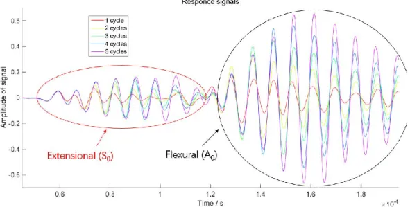
Fig 3-6 Response signals of a plate with different excitation signals ... 45
Fig 3-7 Samples to be tested: the Poisson’s plates... 47
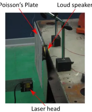
Fig 3-8 Experimental setup for Resonalyser method ... 48
Fig 3-9 Experimental setup for Time-of-Flight method ... 49
Fig 3-10 Plate diagram and axis system [113] ... 52
Fig 3-11 Dispersion curves for Lamb waves in steel [117] ... 54
Fig 3-12 Co-existing plate modes [56] ... 55
Fig 3-13 Sample used for the method validation ... 55
Fig 3-14 Response signals of all the sinusoidal bursts for an aluminum plate ... 56
Fig 3-15 Flowchart of the method ... 57
Fig 3-16 Response signals on composite structure ... 58
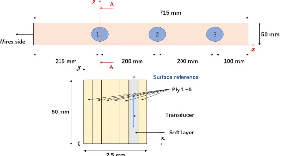
Fig 4-1 Smart composite beam specifications (overview of the beam with 3 embedded transducers, and section cut, at transducer #1 location, located between the 5th and 6th plies)... 65
Fig 4-2 Manufacturing process ... 66
Fig 4-3 Experimental setup for Resonalyser Method ... 67
Fig 4-4 Mesh used for the finite element model (the blue area is the “soft layer”) ... 69
Fig 4-5 Convergence curve for the first eigenfrequency ... 69
Fig 4-6 First five natural elastic bending mode shapes of Beam (c)... 72
Fig 4-7 Relative evolution of the eigenfrequencies vs location of the "soft layer" for the first 5 bending modes ... 74
Fig 4-8 Modal amplitude vs location of the "soft layer" for the first 5 bending mode . 76 Fig 4-9 Experimental setup for Time-of-Flight method ... 77
Fig 4-10 Overview of the spherical cap ... 79
Fig 4-11 Dedicated experimental setup for the spherical cap ... 80
Fig 4-12 The first two eigenmodes of the spherical cap ... 80
Fig 4-13 Mesh of the spherical cap ... 81
Fig 4-15 Visualization of the back face of the spherical cap ... 83
Fig 4-16 Smart composite plates ... 85
Fig 4-17 Smart composite plates with different composite materials ... 87
Fig 4-18 Sensitivity study of the influence of Poisson’s ratio and Young’s modulus on velocity of S0 wave ... 88
Fig 4-19 Experimental setup ... 89
Fig 4-20 Heat flow vs Temperature curve obtained from DSC analysis ... 92
Fig 4-21 Young’s modulus along each wave direction at room temperature ... 93
Fig 4-22 Response signals on Path 1-4 of Plate (b) under different temperature ... 94
Fig 4-23 Young’s modulus vs Temperature on Path 1-6 ... 96
Fig 4-24 Experimental setup and a test sample for DMA... 97
Fig 4-25 Relative attenuation of Young’s modulus from T-o-F (left) and DMA (right) on Path 1-2 of Plate (a) ... 98
Fig 4-26 Relative attenuation of Young’s modulus from T-o-F (left) and DMA (right) on Path 1-2 of Plate (b) ... 98
Fig 4-27 Relative attenuation of Young’s modulus from T-o-F (left) and DMA (right) on Path 1-2 of Plate (d) ... 99
Fig 4-28 Relative amplitude vs Temperature on Path 1-6 ... 101
Fig 4-29 Decrease of Young’s modulus on each direction of Plate (b) ... 102
Fig 4-30 Decrease of Young’s modulus on each direction of Plate (c) ... 102
Fig 4-31 Comparison of Plate (c) before & after the experiment ... 103
Fig 4-32 Samples to be tested - the Poisson’s plates ... 107
Fig 4-33 Response signals of different hole diameters on each path ... 109
Fig 4-34 FFT of response signals on each path ... 110
Fig 4-35 The tendency of T-o-F vs hole diameter for each path ... 112
Fig 4-36 The Peak of FFT amplitude vs hole diameter on each path ... 114
Fig A-1 Polish of the glass ... 121
Fig A-2 Preparation of the materials ... 122
Fig A-3 Cutting of the mat of glass fiber ... 123
Fig A-4 Arrangement of fiber mats and soft layer ... 123
Fig A-5 Arrangement of the drainage materials ... 124
Fig A-6 Injection of the resin ... 125
List of Figuresxvii
xvii Fig A-8 Cutting the beams ... 127
1
CHAPTER 1. INTRODUCTION
Composite materials are widely used in industry field due to their high stiffness and strengthen, low mass density, as well as excellent fire and fatigue resistance. Moreover, composite materials are generally not sensitive to the chemicals commonly applied in engines and do not corrode. A composite material can be defined as a combination of more than two kinds of materials, to have better properties than those from each of the components when they are used alone [1]. Most of the time, the composite materials refer to the materials made of polymer matrix and strong fibers [2]. The polymers have replaced many of the conventional materials in various applications over the past few decades, due to their low cost, their ease of processing and their productivity. To suit the requirement of high stiffness and strength needed for industrial applications, fiber-reinforced polymers come into vogue [3]. As a result, the composite materials own the intermediate mechanical performance of the fibers and the polymers, as well as some other specific properties, like excellent resistance to fatigue, creep, low coefficient of thermal expansion, etc. [4].
However, there are still some shortcomings for the composite materials, which can be summarized as follow [1-5]: low damping ratio; mechanical performance can be easily influenced by temperature or moisture; weakness to ply separations or delamination; inability of yielding; difficulty to be refurbished, toxicity of the smokes from combustion; etc.
Then, this led to the evolution towards Smart Composites. This category corresponds to a composite materials that can change their properties according to various stimuli: under a certain input, they can produce a predictable output [6]. This input can be, for example, specific wavelengths of light, temperature changes, movement, deformation, pressure, chemical concentration, electric field or magnetic field, while the output produced can be changes in color, light, temperature, deformation, stress, stiffness or viscosity, electric field, magnetic field or electrical resistance. This can be illustrated by Figure 1-1, which links the input, on the left-hand side, with the output on the right-hand
side for each type of functional material. The different types of materials are represented by a link between the input and output associated to them. For example, photochromic materials are represented by the link between the input ‘Light’ and the output‘Color’.
Fig 1-1 One possible classification of smart materials [6]
According to Addington and Schodek [7], most of these smart materials have five characteristics in common: immediacy, transiency, self-actuation, directness and selectivity. The immediacy means these materials react as soon as the stimuli appear, i.e. they have an immediate response. The transiency is related to the fact that they react to more than one environmental state, and have different properties depending on these various environmental states. Self-actuation means the special properties are internal of the materials and are not produced by some external actions on the materials. Directness represents the fact that the response of the material is local, and the output is produced at the point where the input was given. Last of all, selectivity qualifies the predictable and
CHAPTER 1 Introduction 3
3 repeatable characteristic of the response. So, a single environmental state can only lead to a unique and constant response of the material.
A smart structure can be defined as a composite structure with some functional materials, like actuators, sensors, or can be regarded as a structure made of smart composite materials. Figure 1-2 depicts the standard architecture of a smart composite structure.
Fig 1-2 Architecture of a smart composite structure [8]
G. Akhras has compared the basic components of a smart structure to the human body [9], as shown in Figure 1-3:
Data Acquisition (tactile sensing): the aim of this component is to collect the
required raw data needed for an appropriate sensing and monitoring of the structure.
Data Transmission (sensory nerves): the purpose of this part is to forward the raw
data to the local and / or central command and control units.
Command and Control Unit (brain): the role of this unit is to manage and control
the whole system by analyzing the data, reaching the appropriate conclusion, and determining the actions required.
Data Instructions (motor nerves): the function of this part is to transmit the
decisions and the associated instructions back to the members of the structure. Action Devices (muscles): the purpose of this part is to take action by triggering
the controlling devices / units.
Fig 1-3 The basic five components of a smart structure [9]
Thoroughly, the smart composite structures have three main components: the fiber & matrix, the reinforcement forms, and the transducers. The transducers are the key component of smart composites.
Fiber / matrix type
It is highly important to choose the fiber / matrix type according to the technical requirements, like mechanical strength or stiffness, temperature stability, structure weight, etc. The most widely used types in the literature are summarized as follows:
- Carbon Fiber Reinforced Polymer (CFRP)
This usually means carbon / graphite fibers with an epoxy resin [10, 11]. - Glass Fiber Reinforced Polymer (GFRP)
This usually corresponds to glass fibers with an epoxy resin [12, 13], or glass fiber with a polyester resin [14-16].
- Natural Fiber Reinforced Polymer (NFRP)
This usually means natural / bio fiber with an epoxy resin [17, 18]. Reinforcement forms
The reinforcement forms concern on the arrangement way of fibers, which can influence the final mechanical properties of the manufactured products [19]. As shown in
CHAPTER 1 Introduction 5
5 Figure 1-4, the fibers used in composite materials and structures appear at different scales and under different forms.
Fig 1-4 Fiber forms at different scales [20]
For example, the mat is a sheet-like material consisting of randomly oriented chopped fibers which are held together by a binder [21, 22], while the unidirectional fabric is a fabric in which most of fibers run in the same direction [23, 24].
Transducers
The transducers are key components in smart composite structures. A transducer is able to operate as an actuator or as a sensor. In the industrial applications, the most widely used transducers can be summarized as follows:
- Ultrasonic transducers
Ultrasonic transducers are a type of acoustic transducer divided into three broad categories: transmitters, receivers and transceivers. Transmitters convert electrical signals into ultrasound, receivers convert ultrasound into electrical signals, and transceivers can both transmit and receive ultrasound [25]. One of the most widely used transducers are ultrasonic probes, due to their excellent precision and controllability [26, 27]. However, the non-negligible mass / volume of the probes as well as the limited access to complex geometry often
reduce their practical applications, even though some very small devices are appearing nowadays, the high price is still an unignored problem. Moreover, such methods may be less efficient for detecting near-surface damage, where reflections from a defect are limited within the wavelength of the transmitted ultrasonic pulse [28].
- Transducers with optical fibers
An optical fiber is a flexible, transparent fiber made by drawing glass (silica) or plastic to a diameter slightly thicker than that of a human hair. Optical fibers are used most often as a means to transmit light between the two ends of the fiber and find wide usage in fiber-optic communications [29]. With lightweight, immunity to electromagnetic interference, wide bandwidth, good compatibility, long life and low power consumption and cost, optical fiber sensors have been increasingly adopted [30]. In most approaches, fiber optic devices are used for capturing static or quasi-dynamic strain, with the capacity to measure strain at two-to-three orders of magnitude better resolution than conventional electrical resistance strain gauges. However, applications with a sensor to detect dynamic Lamb wave signal in the ultrasonic range are relatively rare [31], because of the low sampling rate of the normal optical spectrum analyzer.
- Piezoelectric transducers
Piezoelectric transducers, which can generate an electrical charge in response to mechanical strain, or conversely, can provide a mechanical strain as a result of the applied electrical field, deliver excellent performances in wave generation and acquisition and are particularly suitable for integration into a host structure as an in-situ generator/ sensor, for their low mass/volume, easy integration, excellent mechanical strength, wide frequency responses, low power consumption and acoustic impedance, as well as low cost [32, 33]. Today, the most widely used functional materials in smart structures are probably piezoelectric ceramics. The major advantages of using piezoelectric ceramics in smart structures include [34]: no magnetic field generated in the conversion of electrical energy into mechanical motion; excellently fast response time; high resolution in mechanical positioning, as well as a large force output. However, small driving force / displacement, brittleness, short
CHAPTER 1 Introduction 7
7 fatigue life, etc., might be some concerns limiting applications that need to be solved [35].
In this project, piezoelectric ceramics are chosen as transducers. In the literature, two standard geometries are used for the piezoelectric transducers: disk and rectangular plate. The complex geometries for transducers are not widely used because of the difficulty to predict their final transducing behavior. All the transducers have a high aspect ratio due to a low thickness with respect to the characteristic length. This low thickness limits the intrusiveness of the piezoelectric inclusions with respect to the host composite structure [36].
Tab 1-1 Geometries and dimensions of embedded piezoelectric transducers in the literature Geometry Diameter (mm) Area (mm2) Thickness (mm) Reference Disk 6.35 - 0.254 [37] Disk 10 - 0.2 [38] Disk 20 - 0.2 [39] Disk 25 - 0.135 [21, 22] Plate - 30.1*97 0.07 [23]
Plate - (no data) 0.125 [40]
Plate - 15.5*24.5 0.127 [10]
Plate - 10*10 0.13 [41]
Plate - 50*8 0.2 [42]
Plate - 50*30 0.2 [42, 43]
Plate - (no data) 0.25 [40]
Plate - 50.8*25.4 0.254 [44, 45]
Plate - 17.8*17.8 0.3 [12]
Plate - (no data) 0.3 [40]
Disk 5 - 0.5 [46]
Disk 10 - 1 [46]
As detailed in Table 1-1, in most cases, the transducer thickness is selected to be inferior to a ply thickness (typically ≤ 0.3 𝑚𝑚). Few authors have embedded transducers with a thickness superior to 0.3 mm [43, 46]. This choice implies specific inclusion techniques in order to respect the technical requirement concerning the limitation of the thickness variations of the host structure. The surface area of all the transducers are quite limited with respect to this of the host composite structure. The objective is to build complex shaped structures without a local stiffening due to the piezoelectric implants in order to avoid stress concentrations.
Different manufacturing techniques are available for the manufacturing of smart composite structures. These manufacturing techniques can be divided into the bonding techniques and the so-called in-situ manufacturing techniques, according to the way to include the transducers into the structures [40], as shown in figure 1-5.
Fig 1-5 Manufacturing techniques for active structures with integrated piezoelectric elements [40]
The difference between both manufacturing techniques is the time of integration of the transducers into the structures. In the case of in-situ manufacturing methods, the transducers can only be integrated during the manufacturing of the structure itself, whereas in the case of the bonding techniques, they can be later attached to a surface of the structure to be controlled. The criteria for the classification of the manufacturing techniques shown in Figure 1-5 results from the type of host material of the structure to
CHAPTER 1 Introduction 9
9 be controlled. For a structure with embedded transducers, the mechanical and thermal loads during the machining of the host material have to be within the bounds of the operation range of the integrated control elements.
Conventionally, to create a smart composite structure, the transducers and the electrical conductor network are glued onto the surface of the structure and the power and control electronics are located outside the structure. The transducers efficiency strongly depends on the stiffness of the bond, since the actuation strain of the control elements has to be transferred through the bond. Due to the low stiffness of bonding materials compared to those of the transducers and the host materials, the efficiency of the transducer to induce deformation in the structure decreases with increasing bond thickness. Therefore, bonding layers should be avoided or kept small as is possible with the embedding method.
The approach in this project is significantly different. We have exploited the ability of integration given by the composite material. With this process, the idea is to protect the transducing elements and their electrical connections and to industrially develop end product.
In this project, we are particularly interested in smart composites embedding a distributed set of transducers, which add complexity to the manufacturing aspect. In order to guarantee the transducers efficiency and keep the geometrical and material properties of the host composite structure, several major technical issues are identified as having a strong impact on the manufacturing requirements [8, 47]. It is necessary to:
Electrically connect many transducers to act on the structure. This is the condition to take advantage of a distributed network. With a distributed control network, it is possible to modify the structural behavior of a system over a large excitation frequency range or, more generally, over a large multi-physical excitation range.
Make electrically-independent each transducer. This is an issue, for example, for the development of carbon-fiber-reinforced composite structures which are naturally conductive. The use of semi-finished products can provide a good electric insulation solution.
Perfectly couple the exogenous element with the composite material so as to guarantee the transducers efficiency and reduce the risks of delamination or other failures.
Accurately master the location of the transducers into the structure. For example, this is necessary if we want to create symmetric arrays of transducers and so a highly-symmetric distributed network. This approach can provide advantage in particular to control the guided waves propagating into a thin structure.
Limit the cross-talk between the different embedded elements. A technical requirement has to be defined in order to set a design rule concerning the minimum pitch between two electrical conductors or the minimal distance between two transducers.
Limit the thickness variations due to the piezoelectric inclusions. These inclusions inside the material will inevitably modify locally the thickness of the structure. This fact may be limited using thin piezoceramics (about 150 μm). Moreover, the electrical connection by conventional welding is not advised because of the resulting thickness excess and the possibility to create a wedge, which can break the piezoceramics during the manufacturing process.
Achieve specific shaped structures (for instance, bi-concave structures) so as to adapt to a wide range of real applications.
Achieve a robust link with the structure outside to provide energy or modify the control law or the behavioral law in real time.
Include the recycling and/or the final disposal aspects in the manufacturing or design process (i.e. bio-sourced materials).
To meet all these requirements, specific manufacturing methods have been developed [22, 39]. The manufacturing process is given in Appendix A.
The core of the embedding techniques is the way of including the piezoelectric transducers at the heart of the composite structure. These techniques are very important to master the location of the transducer along the thickness-axis and into the composite structure. The easiest method is to directly place the transducer between two plies [40, 46]. For this, the transducer thickness has to be low with respect to the typical ply thickness. With this technique, the continuity of the different plies is guaranteed. However, resin pockets may appear at the transducer boundaries as depicted in Figure 1-6. These resin pockets can create structural weaknesses conducting, for instance, to an initiation of delamination. Moreover, the transducer location is not accurately guaranteed because the
CHAPTER 1 Introduction 11
11 piezoelectric element can move during the compaction and resin spread. It is necessary, for instance, to glue the transducer on a ply with a glue compatible with the resin.
Fig 1-6 The cross-section of a completely embedded bulk piezoelectric element without a cut-out [40]
Fig 1-7 The cross-section of a completely embedded bulk piezoelectric element with a cut-out [40]
Another method is to use a ply with cut-out [44, 45], which has the exact geometry of the transducer. As shown in Figure 1-7, the volume of the resin pocket is limited and the structure thickness is mastered. However, some discontinuities are created in the fibre layer. Moreover, for complex structures, the geometry of the cut-out and the accurate positioning of the transducer can be difficult to obtain. Both techniques have another disadvantage. They are well adapted for electrically insulated composite material but difficult to use in carbon fibre-reinforced composite structures which are naturally conductive. The use of semi-finished products can provide a good electric insulation solution and solve other major disadvantages.
One example is the Stanford Multi-Actuator-Receiver Transduction Layer ("SMART Layer"), which has been developed by Lin and Chang [48, 49]. It is used to integrate a network of distributed piezoceramic transducers into the heart of the graphite/epoxy
composite laminates in their manufacturing process. For this, a semi-finished product based on a polyimide encapsulation for the transducers, is created during an additional manufacturing step. They have demonstrated that the embedded transducers can be used without degrading the structural integrity of the host composite structures [37]. However, this solution needs to pay a particular attention to the ratio between the semi-finished product surface and the overall product surface because the encapsulation material and the matrix have not the same chemical nature. If this ratio is too high, delamination problems could occur. This is the reason why another technology has been developed in UTBM. A glass-fibre reinforced plastic (GFRP) composite with two plies sandwiching the transducers and impregnated with a resin compatible with that of the final composite structure has been used to create a "soft layer” as a semi-finished product [21]. This will be discussed in Chapter 2. The development of this manufacturing process is still ongoing.
In parallel, a design approach is also developed in this project. In the frame of mechanical and electrical engineering, the majority of designers uses several models at the different levels of the V-model design process, as shown in Figure 1-8.
CHAPTER 1 Introduction 13
13 This project is concentrated on the first two steps: “Concept of operations” and “Requirements and architecture”, which can be defined as the preliminary design or preliminary study. One should reach consensus at the very beginning of the project on what will constitute success at the end [51].
The preliminary design of this project can be regarded as that we take the M main input specifications of the design as input and calculate the N design parameters of the model as output. In practice, the problem is quite complex as, in general, we have 𝑁 ≫ 𝑀. Thus, we need to offer an efficient way to calculate those N design parameters starting from only the M main input specifications. In industrial applications, complex and heterogeneous requirements have to be satisfied. Because multiple requirements are hardly manageable by a single optimization model, preliminary design is required to guarantee that such requirements can be satisfied.
To support the necessity of preliminary design, F. Wurtz reports an interesting assessment in the fields of energetic equipment for buildings: whereas preliminary studies represent only 5% of the total costs of a project, the resultant decisions fix 75% of the impact of project [52]. This necessity is also illustrated on the Figure 1-9 concerning design in aeronautics: 80% of the life cycle cost are set by design choice during preliminary study phases [53].
For our design approach, the system engineering tools are exploited. First of all, the Product Breakdown Structure (PBS) is built. A simplified version of this PBS is given in figure 1-10.
Fig 1-10 Simplified PBS of an adaptive composite structure
The product is broken down in sub-systems and in components. This process is iterative and is repeated for different depth levels. This process is stopped when the components are indivisible, are commercial off-the-shelf components or can be designed by only one development team in the project team. Once the down tree obtained, it is necessary to establish the system architecture. The different elements of the product tree are organized with respect to their interfaces. Thus, the interfaces between the components are defined. The major issue of a complex system design is not the individual design of the components, in general managed by one project team. The major issue is to design the components interacting with their environment and with the other components. To summarize, the key point is to manage and well-design the interfaces between the components. Figure 1-11 is an example of a simplified system architecture established for an adaptive composite structure.
CHAPTER 1 Introduction 15
15 Fig 1-11 Simplified system architecture of an adaptive composite structure (Interfaces
management)
Based on the design approach selected, it is possible to establish the essential experimental characterizations, and to well-know the overall system behavior with the integrated piezoceramic transducers. Our approach is based on an experimental approach upstream by predicting the overall physical parameters of the manufactured composite structure. The system architecture is used to specify the experimental characterization needs and so the procedures to be developed. Consequently, it is necessary to develop:
A characterization of piezoelectric ceramics
A non-destructive process, based on the vibration analysis of poles and zeros of the transducers, is developed and used for obtaining the coupling coefficients of interest [54]. This is discussed in Chapter 3.
A characterization of the manufactured composite material
Once the manufacturing process stabilized, the composite must be fully characterized using a set of tests allowing to have access to materials nominal parameters and their uncertainty. For this, two major methods are exploited: The Time-of-Flight method [55, 56] and the Resonalyser method [57, 58], which are detailed in Chapter 3.
The objective is to be able to produce a generic behavior modeling of material parameters and coupling coefficients, when integrating the piezo ceramics inside the material. This step is not investigated in this work.
A characterization of the impact of manufacturing process
The objective is to master the impact of the manufacturing process on the mechanical characters of the smart composite, as the development of the manufacturing process is still ongoing. This research can thus give a good reference to the improvement of the manufacturing process. The work is detailed in Chapter 4.
A characterization of the influence of temperature
The influence of the temperature on the behavior of smart composites structures is significant, it consists of both the influence on the piezoelectric transducers and that on the composite materials. The objective is to study about the influence of the temperature and built a database to service all stakeholders. This work is presented in Chapter 4.
A characterization of the impact of damages
The objective of studying the sensitivity of smart composite structures on the damages, is for developing the potential ability of smart composite structures on structural health monitoring (SHM), which is one of the future applications of the smart composites in this project. In Chapter 4, this analysis is given. As discussed above, it is impossible to consider all the parameters at once during the preliminary design, the objective at this stage is to find out the main problems and master them. The experimental characterizations mentioned above is the top few problems addressed by now.
The characterization methods are another key element in the study. Especially the characterization methods for the composite material, which will be applied in most of the analysis in this project, such as characterization of the manufactured composite material, characterization of the integrated piezo ceramics, characterization of the impact of manufacturing process, characterization of the influence of temperature, and characterization of the impact of damages.
As shown in Figure 1-12, the characterization methods of composite materials can be sorted into two main parts: destructive techniques and non-destructive techniques.
CHAPTER 1 Introduction 17
17 Destructive techniques can be mainly classified as classical static approaches that involve static mechanical tests, such as tensile test, compression test, bending test, torsion test, etc. to acquire the stresses and strains of a specimen. Direct identification of elastic constants of composite materials can be done based on the fundamental stress-strain theory. For composite materials, the procedures are more cumbersome and time-consuming due to the need of several specimens’ analyses to obtain all the elastic constants. Moreover, in some cases, it is unacceptable to take out a test sample from a larger structure made of composite materials because of the disruption of the internal coherence of the material.
Fig 1-12 Overview of composite material properties identification methodologies [59]
Meanwhile, non-destructive techniques involve two parts, which are the experimental part and numerical part. In the experimental part, measurements of significant parameters and data extraction will be conducted for subsequent use in numerical part. The numerical part involves the use of forward or inverse methods for evaluation of elastic properties of
composite material. Basically, there are two types of non-destructive measurement approaches for the composite material identification, which include wave propagation methods and vibrational methods. Wave propagation methods usually adopt the application of ultrasonic wave passing through a specimen. These data are related to the material parameters. The emitting and receiving transducers used in most studies are piezoelectric transducers due to cheap price and light weight [47, 48]. For the wave propagation methods, there are bulk-wave-based methods [60, 61] and guided-wave-based methods [61, 62]. Bulk-wave-guided-wave-based methods are usually used in material properties identification of thick composite materials via through-transmission or back-reflection techniques [60, 61]. Meanwhile, in guided-wave-based methods, Lamb waves, also known as guided waves, are usually generated and guided between two parallel free surfaces of a plate or shell. Lamb-wave-based methods are known to be a good choice for thin plate analysis [62-64]. However, in general, due to several disadvantages of wave propagation methods, such as complex dispersive characteristics of waves, the formation of several waveforms in single frequency waves, complex procedures, and the need of active power, vibrational methods appear to be an interesting alternative in material identification to eliminate those drawbacks [65]. In vibrational methods, external excitations on the specimens are needed and modal parameters such as natural frequencies, modal damping and the mode shapes of the specimen are extracted from the obtained frequency response functions (FRFs) [58, 62]. Usually, the natural frequencies and vibration shapes of the specimen are taken as primary parameters in determining the elastic properties of a composite material. In this project, the Resonalyser method is taken as a reference characterization method, which is described in Chapter 3.
However, the complexity of applying the Resonalyser method to large structures or the need for specific samples to be tested limits its application in modern industry. Due to the development and high requirement on composite materials, an early characterization is critical for maintaining the integrity of structures in use. Thus, more and more studies are concentrated on the in-situ material characterization [62]. So, the Time-of-Flight method is taken into study also in this project, which can be used as an in-situ material characterization method [16]. To overcome the drawbacks about the wave propagation methods mentioned in front, a new method is also developed in this project. This is a numerical-experimental method based on Time-of-Flight techniques, which is given in
CHAPTER 1 Introduction 19
19 Chapter 3. Another significant advantage of this method is that it is relatively easy to extract the Poisson’s ratio, the measurement of which is still difficult.
The objectives of this project can be summarized as:
Propose a design methodology of smart composite structures, and focus on the preliminary design stage, which represents only 5% of the total costs of a project, whereas 80% of the life cycle cost are set during the preliminary study phases.
Address the top few problems for the design of smart composite structures, like characterization of piezoelectric transducers and composite material, the influence of transducers location, manufacturing process, temperature and damage on the behavior of the smart composite structures.
Introduce a semi-finished product, “soft layer”, which is applied to embed the transducers system into the composite structures. Compile the manufacturing process of “soft layer” as well as the smart composite structures.
Exhibit some smart composite structures manufactured in the research team of this project and discuss the potential applications of those smart composite structures.
Develop a characterization method of composite material, which is a low-cost and in-situ method, to extract elastic constants, especially the Poisson’s ration, easily and fast.
Investigate the sensitivity of smart composite structures to various elements, such as transducers location, manufacturing process, temperature as well as mechanical damages.
The organization of this thesis is as follows:
In Chapter 2, an introduce to the smart composite structures and the “soft layer” will be given, as well as a summary of the manufacturing process. Then the smart composite structures manufactured in the lab, as well as their potential applications will be discussed.
The characterization of piezoelectric transducers and the composite materials will be discussed in Chapter 3. The characterization results of the transducers will be given directly in this chapter, as all the smart composite structures use the same kind of transducers in this project. Two characterization methods of composite materials: Resonalyser method and Time-of-Flight method, will be studied. At the
end, a low-cost and in-situ characterization method will be developed, to extract the elastic constants, especially the Poisson’s ratio of composite material.
Some experimental studies will be discussed in Chapter 4, which focuses on the sensitivity of smart composite structures to various parameters. Sensitivity analysis consists of the influence of transducers location, the impact of manufacturing process, the influence of temperature and the impact of damage on smart composite structures.
Finally, the conclusions and recommendations for future works will be given in Chapter5.
21
CHAPTER 2. SMART COMPOSITES
In aerospace, civil and mechanical engineering applications, smart composite structures are widely used, due to their considerable advantages in terms of vibration attenuation, strength, reliability, integration and low mass density. The potential applications of the smart composite structures with transducers included at the heart of the material in this project are numerous, like vibration control, energy-harvesting, mechatronic, self-healing, structural-health-monitoring or fatigue management [66]. They can be unobtrusively integrated into the composite structure, can be operated as sensors for structural health monitoring and strain measurements and can, of course, serve as sensors and actuators in actively controlled structures. Four main application fields are presented here [8]:
Vibration attenuation
Mechanical vibrations can have a negative impact on systems [67]: failures can occur by fatigue, by excessive strain during transient events or by instability. Vibrations and noise influence customer’s comfort. In precision engineering (optical systems, machining, etc.), vibrations limit the operating conditions of the systems.
The smart composite structures can modify their own properties (damping, stiffness, acoustic impedance, etc.) in order to modify their vibration or vibroacoustic behaviors and so manage these drawbacks. For instance, it is possible to design a smart composite structure dedicated to the vibration isolation of sensitive electronic components such as Bulk Acoustic Wave resonators [68] or inertial platforms [69].
Structural Health Monitoring (SHM)
Balageas has defined Structural Health Monitoring as the ability to give, at every moment during the life of a structure, a diagnosis of the state of the constituent materials, of the different parts and of the full assembly of these parts constituting the structure as a whole [70].
The embedded transducers network can check the quality or the ageing of the host composite structure over a period of time. This network is able to detect a fiber crack or
other failures. Associated to micro-controller and specific algorithms, the generated data can be used to locate flaws or to predict failure events [71].
Energy Harvesting (EH)
Energy harvesting is a technical method to extract energy from external sources (base vibrations, wind, thermal gradient, sea wave, etc.) [72].
The development of EH devices is in progress for the different types of external sources. In piezoelectricity field, these devices and the technologies used are particularly sophisticated. Thus, it is possible to integrate these EH devices into the composite structure and for instance supply electric energy from vibration energy. Currently, the available electric power is quite limited. But, by distributed network effect, micro-controllers or operational amplifiers could be autonomous and so the overall network too [73].
Internet of things
The Internet of Things has been defined as a global infrastructure for the information society, enabling advanced services by interconnecting (physical and virtual) things based on existing and evolving interoperable information and communication technologies [74]. By embedding sensors, actuators and communication devices, the connection between physical and virtual worlds is possible.
For all these applications, the core elements for embedding the transducers into the smart composite structures in this project is the “soft layer”, a semi-finished product to protect the connection of transducers system, keep the transducers be isolative, and guarantee the location of the transducers when they are embedded into the composites. In this chapter, at first, the “soft layer” is introduced. Then a summary of the manufacturing process about the smart composites is given. At last, there is an exhibition of the smart composite structures manufactured in this lab, and the potential applications of these structures is discussed.
2.1 Soft Layer
As already mentioned, the key point of the manufacturing technology is the way of embedding the smart material during the manufacturing process. The easiest method is to directly place the transducers between two plies, but resin pockets appear at the transducer boundaries, which can create a structural weakness [40]. Moreover, the transducer location is not accurately guaranteed because the piezoelectric elements can
CHAPTER 2 Smart Composites 23
23 move during the compaction and resin spread. Another method is to use a ply with cut-out. The cut-out has the exact geometry of the transducer, but some discontinuities are created in the fiber layer and have an impact on the durability of the product [75]. An analytical study performed by Chow and Graves has proved that the insertion of transducers can affect the integrity of smart structures [76]. The results show that the magnitude of inter-laminar stresses in a graphite/epoxy laminate increases by five times, due to the presence of embedded inert rectangular implant. Hansen and Vizzini have performed static tension and tension-tension fatigue tests on carbon/epoxy composites with inserted glass slices [77]. Their results show that embedding techniques have significant influence on the static and fatigue strengths of the composites. Particularly, compared with the interlacing technique, the cut-out method can significantly degrade the fatigue life of embedded composites. Moreover, for complex structures, the geometry of the cut-out and the accurate positioning of the transducers can be difficult to obtain.
Furthermore, there are many other issues needed to be addressed during the manufacturing process, like electrical insulation, protection of elements and their connection, structural integrity, labor requirement, etc.
For example, the first problem “electrical insulation” aims at avoiding short-circuit of sensors in some materials like carbon fiber reinforced polymer (CFRP) composite. The carbon fibers are conductive, as a result, the embedded sensors become short circuited and out of function. One method developed previously to solve this issue is to wrap each piezoelectric ceramic as well as their wires with an insulating film [78, 79]. This method is rather labor intensive when a large number of transducers are needed, and it can increase the size and weight of the integrated element, which can result in strength and weight penalties of the composite structures.
Specific manufacturing methods have been developed to place the transducers system at the heart of the composite material. Stanford Multi-Actuator-Receiver Transduction Layer ("SMART Layer") has been developed by Lin and Chang [48], which is used to integrate a network of distributed piezoceramic transducers into the heart of the graphite/epoxy composite laminates in their manufacturing process. For this, a semi-finished product based on a polyimide encapsulation for the transducers, is created during a supplementary manufacturing step. They have demonstrated that the embedded transducers can be used without degrading the structural integrity of the host composite structures [37]. But, this solution needs to pay a particular attention to the ratio between
the semi-finished product surface and the overall product surface because the encapsulation material and the matrix have not the same chemical nature. If this ratio is too high, delamination problems could occur. This is the reason why another technology has been developing. A glass-fiber reinforced plastic (GFRP) composite with two plies sandwiching the transducers and impregnated with a resin compatible with that of the final composite structure has been used to create a "soft layer” as a semi-finished product [80-82]. As shown in Figure 2-1. The major features of the soft layer include:
The installation is simple;
The transducers location is mastered;
The “soft layer” location along the thickness-axil of the host structure can be also mastered;
The elements as well as their connection can be protected; The electric insulation is guaranteed;
The host material (the resin) is uniform with that of the composite structures.
Fig 2-1 The “soft layer” used during manufacturing process
During the manufacturing of the “soft layer”, the piezoceramics are positioned at accurate locations on one light glass fiber ply (surface mass of 30 g/𝑚2). Another light
glass fiber ply is positioned on the transducers. Then this dry device is reinforced with the same polyester resin used for the whole composite structure in order to guarantee the continuity of the material properties. The later step is optional: it depends on the
CHAPTER 2 Smart Composites 25
25 structures, if the structure is simple, the “soft layer” can be embedded directly during the manufacturing process without reinforced by resin.
2.2 Manufacturing Process
The mixture of fiber / resin does not really become a composite material until the last phase of the fabrication, that is, when the matrix is reinforced [2]. Similarly, the mixture of transducers / composite does not really become a smart composite until the last phase of the manufacturing, that is, when the transducers are embedded. The flow chart in Figure 2-2 shows the process of the smart composite manufacturing.
Fig 2-2 Smart composite manufacturing process
In this project, the main manufacturing process is a Vacuum Assisted Resin Transfer Molding (VARTM) process [81]. VARTM process is a very attractive, cost effective and environment friendly method of composite manufacturing. Several years ago, RTM process has been successfully used for the manufacturing of simple components. However, when one has to manufacture large (5 ~ 6 m) co-cured structures (skin co-cured with spars, ribs and stringers), this process becomes infeasible as ensuring a high fiber volume ratio (around 60%) is extremely difficult due to variation in thickness of the skins, spars and ribs from section to section. Moreover, building rigid molds with all the
clamping requirements will make it economically infeasible. The next improvement came in the form of the Vacuum Assisted Resin Transfer Molding Process (VARTM). It has been shown that a vacuum assistance provides a significant improvement in mechanical properties. This is due to the higher fiber volume fraction and lower void content. The vacuum helps removal of air from within the fiber bundles, which results in lower void content [83].
Fig 2-3 Preparation of the materials for VARTM
As shown in Figure 2-3, No.1 is vacuum bag, a plastic membrane that will cover on all the setup to create a vacuum environment; No.2 is tube, used to transfer the resin into the mold during the process; No.3 is breather / bleeder cloth, a felt for the drainage of the resin; No.4 is release film, a thin plastic for ensure an easy demold of structure; No.5 is peel ply, a kind of fabric to separate the structure and materials for drainage, and to ensure the materials for drainage can be tear off from the structure easily; No.6 is diffusion net, a net for the diffusion of the resin.
During the manufacturing process, the “soft layer” is introduced between two fiber layers. According to the technical requirements, the transducer location is accurately guaranteed by using the “soft layer”. After organizing the laminates, a draining net as well as a tube are used to ensure the resin can feed every part of the structure. The draining net and the feeding tube are put on the top surface of the laminates. A vacuum
CHAPTER 2 Smart Composites 27
27 bag is positioned at the end, covering all the composite structure. A pump is used to achieve partial vacuum in order to compact the fibers and the resin. Then the matrix is reinforced by a polyester resin. After the curing, the structure is demolded. A smart composite structure is then obtained.
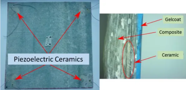
Fig 2-4 Smart composite plate with 4 embedded piezoelectric transducers
As depicted in Figure 2-4, a smart composite plate with 4 embedded piezoelectric transducers is given as an example. As shown in the close-up of Figure 2-4, the piezoelectric transducers are integrated in the composite structure
2.3 Examples of manufactured products
This section presents some examples of structures which have been manufactured in this lab. The products are classified into 2 groups: the test products and the concept products. The test products have been manufactured for the experimental studies, while the concept products are some patterns manufactured in order to illustrate the conception of real product and discuss the potential applications.
All the test products will be introduced in detail in Chapter 4, thus they will not be introduced in detail in this section. In Section 4.1, the smart composite beams for studying the influence of transducers location are introduced. Those beams are made of glass fiber reinforced polymer (GFRP) composite, with piezoelectric transducers located at different location along the thickness axis. In Section 4.2, the smart composites cap for studying the impact of manufacturing process is introduced. The cap is made of glass
![Fig 1-5 Manufacturing techniques for active structures with integrated piezoelectric elements [40]](https://thumb-eu.123doks.com/thumbv2/123doknet/14692650.745639/27.893.160.758.541.871/fig-manufacturing-techniques-active-structures-integrated-piezoelectric-elements.webp)
![Fig 1-8 The V-model of the Systems Engineering Process [50]](https://thumb-eu.123doks.com/thumbv2/123doknet/14692650.745639/31.893.183.721.656.1052/fig-v-model-systems-engineering-process.webp)
![Fig 3-4 Definitions of transit time for use with different definitions of wave speed [55]](https://thumb-eu.123doks.com/thumbv2/123doknet/14692650.745639/61.893.272.657.829.1094/fig-definitions-transit-time-different-definitions-wave-speed.webp)
![Fig 3-5 Dispersion curves for plate wave modes based on elasticity theory [55]](https://thumb-eu.123doks.com/thumbv2/123doknet/14692650.745639/62.893.167.719.593.956/fig-dispersion-curves-plate-modes-based-elasticity-theory.webp)
![Fig 3-11 Dispersion curves for Lamb waves in steel [117]](https://thumb-eu.123doks.com/thumbv2/123doknet/14692650.745639/73.893.240.659.129.800/fig-dispersion-curves-lamb-waves-steel.webp)