HAL Id: tel-02163227
https://tel.archives-ouvertes.fr/tel-02163227
Submitted on 24 Jun 2019HAL is a multi-disciplinary open access
archive for the deposit and dissemination of sci-entific research documents, whether they are pub-lished or not. The documents may come from teaching and research institutions in France or abroad, or from public or private research centers.
L’archive ouverte pluridisciplinaire HAL, est destinée au dépôt et à la diffusion de documents scientifiques de niveau recherche, publiés ou non, émanant des établissements d’enseignement et de recherche français ou étrangers, des laboratoires publics ou privés.
Parallel Robots
Sana Baklouti
To cite this version:
Sana Baklouti. Vibration Analysis and Reduction of Cable-Driven Parallel Robots. Mechanical engi-neering [physics.class-ph]. INSA de Rennes, 2018. English. �NNT : 2018ISAR0034�. �tel-02163227�
During the preparation of my PhD thesis, I had to take the help and guidance of some respected persons, who deserve my deepest gratitude. I would like to thank my thesis director, Mr. Eric RAGNEAU, for having me in his team.
To achieve the target of a thesis work, to put it into shape and to publish, requires regular supervision. Advice, ideas, long discussions and experienced feedback are necessary to progress. I would like to show my sincere gratitude to my supervisors, Mr. Eric COURTEILLE and Mr. Stéphane CARO, for their guidance and effort they have given me throughout my thesis. Your precious ideas guided me in my hesitation, and your scientific rigor allowed to carry out this work. I have great pleasure working with you, and wish you a lot of success in your future research ! A big thank you for these three years very rich in lessons. I hope to have the chance to continue working with you in the future.
I extend a big thank you to Mr. Philippe LEMOINE, the LS2N engineer, who helped me in my experimentations. I really enjoyed our many exchanges !
I would like to thank my reporters, Mr. Edouard LAROCHE and Mr. Marc
GOUTTEFARDE, who took the time to evaluate my work carefully. I also thank
my examiners, Mrs. Hélene PIET-LAHANIER and Mr. Jean-Pierre
MER-LET, for their attention to my work. I enjoyed our discussions and your
construc-tive comments.
Furthermore, I would also like to thank my parents for their endless love and support. You are proud to have a doctor daughter and I am proud to have you parents. I love you !
My gratitude goes to my fiancé who never stopped encouraging me and helping me enrich my technical background. I know I could always count on you... Thank you !
I would like to expand my gratitude to all those who have directly and indirectly supported me.
This thesis aims at improving the static positioning and trajectory tracking ac-curacy of Cable-Driven Parallel Robots (CDPRs) while considering their overall elasticity. Accordingly, two complementary control strategies that are valid for any CDPR configuration are proposed.
First, a robustness analysis is performed to lead to a robust model-based control of CDPRs. As a result, an appropriate CDPR model is defined as a function of the targeted application and the main sources of CDPR moving-platforms pose errors are identified.
A first control method is determined based on the results of the robustness ana-lysis. This first method lies in the coupling of a model-based feed-forward control scheme for CDPR with a PID feedback controller. An elasto-dynamic model of the CDPR is expressed in order to compensate the oscillatory motions of its moving-platform due to cable elongations and its dynamic behavior. The second control me-thod uses input-shaping filters into the proposed model-based feed-forward control in order to cancel the oscillatory motions the moving-platform. Thus, the input signal is modified to make the CDPR self-cancel residual vibrations.
Experimental validations are performed while using a suspended and non-redundant CDPR prototype. The proposed feed-forward model-based control schemes are im-plemented and their effectiveness is discussed. Results show the relevance of the proposed control strategies in terms of trajectory tracking accuracy improvement and vibration reduction.
Cette thèse vise à améliorer le positionnement statique et la précision de suivi de trajectoire des Robots Parallèles à Câbles (RPC) tout en prenant en compte leur élasticité globale. A cet effet, deux stratégies de commandes complémentaires valables pour toute configuration de RPC sont proposées.
Tout d’abord, une analyse de robustesse est réalisée pour aboutir à une com-mande robuste des RPC référencée modèle. Un modèle de RPC approprié est défini en fonction de l’application visée et les principales sources d’erreurs de pose de la plate-forme mobile sont identifiées.
Une première méthode de commande est proposée sur la base des résultats de l’analyse de robustesse. Cette première méthode réside dans le couplage d’une commande référencée modèle avec un contrôleur PID. Dans le cadre de cette thèse, un modèle élasto-dynamique de RPC est exprimé afin de compenser le comporte-ment oscillatoire de sa plate-forme mobile dû à l’élongation des câbles et de son comportement dynamique. La deuxième méthode de commande utilise des filtres "input-shaping" dans la commande référencée modèle proposée afin d’annuler les mouvements oscillatoires de la plate-forme mobile. Ainsi, le signal d’entrée est mo-difié pour que le RPC annule automatiquement les vibrations résiduelles.
Les résultats théoriques obtenus sont validés expérimentalement à l’aide d’un prototype de RPC non redondant en actionnement et en configuration suspendue. Les résultats expérimentaux montrent la pertinence des stratégies de commande proposées en termes d’amélioration de la précision de suivi de trajectoire et de réduction des vibrations.
I.2.2 Error sources affecting accuracy · · · ·40
I.2.3 Control for accuracy improvement · · · ·43
I.3 Objectives and contributions
· · · ·
46I.3.1 Contribution on CDPR modeling · · · ·47
I.3.2 Static and dynamic robustness analysis · · · ·47
I.3.3 Control for CDPR accuracy improvement · · · ·49
II CDPR models and properties 51 II.1 Introduction
· · · ·
51II.2 Rigid dynamic model
· · · ·
52II.2.1 Dynamics of actuators· · · ·55
II.2.2 Complete dynamic model · · · ·56
II.2.3 Determination of the cable tensions · · · ·57
II.3 Dynamic modeling considering cable stiffness : Elasto-static model
· · · · ·
59II.3.1 Cable stiffness modeling· · · ·60
II.3.1.1 Sag-introduced stiffness · · · ·60
II.3.1.2 Axial stiffness · · · ·62
II.3.2 Linear and non-linear cable tension models · · · ·62
II.3.2.1 Non-linear tension of cables with linear damper · · · ·64
II.4 Elasto-dynamic modeling
· · · ·
66II.5 Summary of the chapter
· · · ·
68III Robustness analysis of CDPR 71 III.1 Introduction
· · · ·
71III.2 Error sources affecting CDPR accuracy
· · · ·
72III.2.1 Modeling · · · ·72
III.2.2 Parameters· · · ·72
III.2.2.1 Geometrical parameters · · · ·72
III.2.2.1.1 Base frame geometrical errors · · · ·73
III.2.2.1.2 Moving-platform geometrical errors · · · ·73
III.2.2.2 Mechanical parameters· · · ·74
III.2.2.2.1 End-effector mass · · · ·74
III.2.2.2.2 Cables parameters · · · ·74
III.2.2.2.2.1 Linear mass · · · ·74
III.2.2.2.3 Tension distribution · · · ·76
III.3 Sensitivity analysis of CDPR accuracy to modeling
· · · ·
77III.3.1 Linear and non-linear cable tension models · · · ·77
III.3.1.1 Illustrative example· · · ·78
III.3.1.2 Semi-industrial examples · · · ·82
III.3.2 Sensitivity of CDPR dynamic behavior to the modeling type · · · ·85
III.4 Uncertainty analysis of CDPR to parameters
· · · ·
89III.4.1 Dynamic uncertainty analysis · · · ·89
III.4.1.1 Dynamic stiffening · · · ·89
III.4.1.2 Axial cable damping · · · ·93
III.4.2 Static uncertainty analysis · · · ·95
III.4.2.1 Static deflection · · · ·96
III.4.2.2 Uncertainty range of parameters · · · ·97
III.4.2.3 Uncertainty analysis with unknown tension set-point · · · ·99
III.4.2.3.1 Analysis of the elasticity modulus over the workspace · · · · 101
III.4.2.4 Uncertainty analysis with known tension set-point · · · 102
III.4.2.4.1 Analysis of the natural frequency over the workspace · · · · 104
III.5 Summary of the chapter
· · · ·
105IV CDPR control for accuracy improvement 107 IV.1 Introduction
· · · ·
107IV.2 Feed-forward model-based control
· · · ·
108IV.2.1 Discrete-time control of CDPR · · · 110
IV.2.1.1 Actuation system · · · 110
IV.2.1.2 Feedback control loop · · · 111
IV.2.1.3 Feed-forward control loop · · · 111
IV.2.2 Pre-compensation · · · 112
IV.2.2.1 Rigid pre-compensation · · · 113
IV.2.2.2 Elasto-static pre-compensation · · · 114
IV.2.2.3 Elasto-dynamic pre-compensation · · · 114
IV.2.3 Controller tuning · · · 115
IV.2.4 Numerical results · · · 116
IV.2.4.2 Trajectory tracking · · · 118
IV.2.4.2.1 Transitional phase · · · 120
IV.2.4.2.2 Steady-state phase· · · 121
IV.2.5 Experimental results · · · 124
IV.2.5.1 Test bench · · · 125
IV.2.5.2 Experimental setup · · · 130
IV.2.5.3 Static analysis · · · 131
IV.2.5.4 Trajectory tracking · · · 132
IV.2.5.4.1 Transitional phase · · · 134
IV.2.5.4.2 Steady-state phase· · · 136
IV.3 Input-shaping for feed-forward control
· · · ·
139IV.3.1 Single mode Input-shaping control · · · 142
IV.3.1.1 Zero-Vibration input-shaper · · · 143
IV.3.1.2 Zero-Vibration-Derivative input-shaper· · · 143
IV.3.1.3 Robustness to modeling errors · · · 143
IV.3.2 Multi-mode input-shaping control· · · 145
IV.3.3 Experimental results · · · 145
IV.3.3.1 Trajectory generation · · · 145
IV.3.3.2 Input-shaping · · · 146
IV.4 Summary of the chapter
· · · ·
150V Conclusions and Future Work 153 V.1 Conclusions
· · · ·
153V.1.1 Contribution on CDPR dynamic modeling · · · 154
V.1.2 Robustness analysis · · · 155
V.1.3 Control for CDPR accuracy improvement · · · 156
V.2 Future Work
· · · ·
156A Cable identification : Modulus of elasticity 161 A.1 Steel Cable
· · · ·
161A.1.1 Modulus of elasticity· · · 161
A.1.2 Dynamic modulus of elasticity · · · 164
B Example prototypes 169 B.1 CAROCA
· · · ·
169 B.1.1 Redundant configuration · · · 169 B.1.2 Non-redundant configuration· · · 169 B.2 FAST· · · ·
170 B.3 CREATOR prototype· · · ·
171C Complement for modeling 175 C.1 Euler angles convention
· · · ·
175C.1.1 Angular velocity · · · 176
C.2 Elasto-dynamic model resolution
· · · ·
177I.11 The input shaping process
· · · ·
46I.12 CAROCA prototype : a reconfigurable CDPR (Courtesy of IRT Jules Verne, Nantes)
· · · ·
48II.1 The ith closed-loop of a CDPR
· · · ·
52II.2 Graphical representation of sign versus hyperbolic tangent
· · · ·
57II.3 Schematic of the CDPR rigid model : Planar example
· · · ·
59II.4 Schematic of the CDPR elasto-geometric model with straight cables : Planar example
· · · ·
60II.5 Schematic of elasto-sagging cable
· · · ·
61II.6 Hysteresis loops for a 4 mm steel wire cable preloaded at 1500 N with force controlled sine waves applied at 0.1, 1, 2, 5, 10, and 20 Hz
· · · ·
65II.7 Schematic of the CDPR elasto-dynamic model : Planar example
· · · ·
66II.8 Cable parametrization while considering dead length
· · · ·
68III.1 Error sources affecting CDPR accuracy
· · · ·
73III.2 Load-elongation diagram of a steel wire cable measured in steady state conditions at the rate of 0.05 mm/s
· · · ·
75III.3 Circular helical trajectory : (a) Trajectory and (b) velocities of the end-effector79 III.4 Cable linear velocity profiles
· · · ·
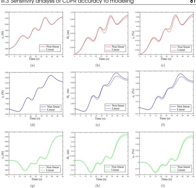
79III.5 Comparison between linear and non-linear tension formulations : Tension, elon-gation and strain for three cables. Time history of (a) τ1 , (b) δl1, (c) s1, (d) τ2, (e) δl2, (f) s2, (g) τ3, (h) δl3, and (i) s3
· · · ·
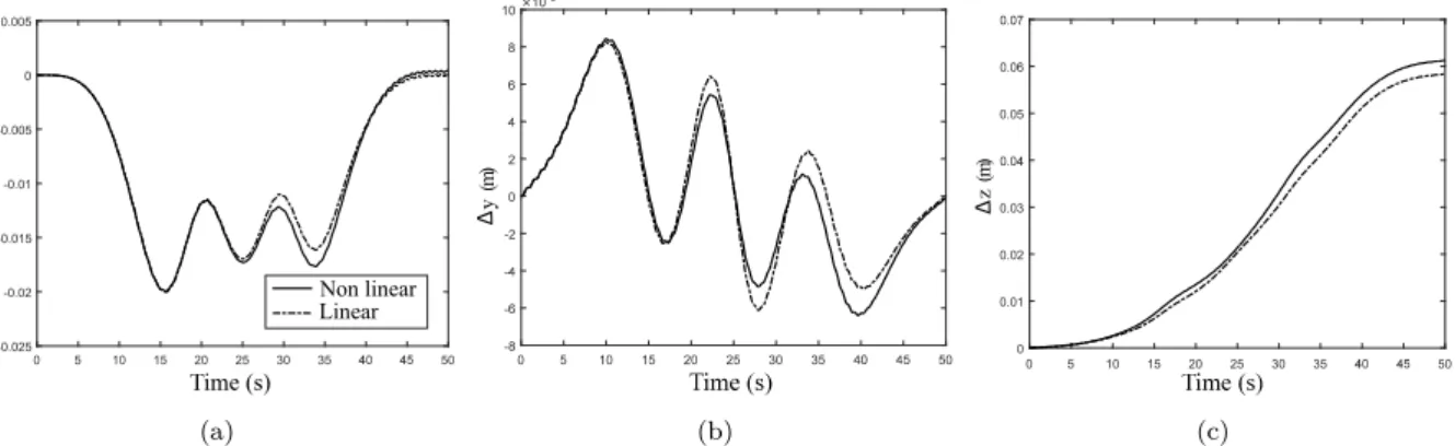
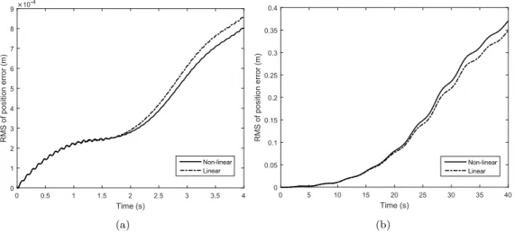
81III.6 Comparison between linear and non-linear tension formulations : Positioning error of the end-effector along (a) x-axis, (b) y-axis and (c) z-axis
· · · ·
82III.7 Schematics of the (a) CAROCA and (b) FAST CDPR
· · · ·
83III.8 Comparison between linear and non-linear tension formulations with respect to CDPR overall size. Time history of (a) τ2 : CAROCA, (b) δl2 : CAROCA, (c) s2 : CAROCA (d) τ2 : FAST, (e) δl2 : FAST and (f) s2 : FAST
· · · ·
83III.9 Positioning errors of the CDPR end-effector calculated with a linear and a non-linear cable tension model, respectively : (a) CAROCA (b) FAST
· · · ·
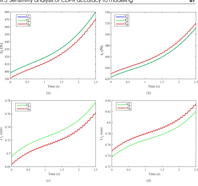
84III.10 (a) Desired position (b) velocity and (c) acceleration of the moving-platform 86 III.11 Comparison between the cable responses while using different CDPR models : Time history of (a) τ1, (b) τ3, (c) δl1 and (d) δl3
· · · ·
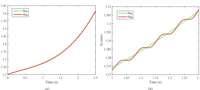
87III.12 Comparison between the different dynamic CDPR models : Time history of (a)
III.13 Trapezoidal-velocity trajectory : (a) Trapezoidal actuation velocities (b)
Trajec-tory of the end-effector
· · · ·
89III.14 Comparison between cables responses while using static or dynamic modulus : Time history of (a) τ1, (b) δl1, (c) s1, (d) τ2, (e) δl2, (f) s2, (g) τ3, (h) δl3 and (j) s3
· · · ·
91III.15 Comparison between the CDPR responses while using static or dynamic modulus : Time history of positioning error along (a) x-axis, (b) y-axis and (c) z-axis
·
92 III.16 Comparison between the CDPR natural frequencies while using static or dynamic modulus (2 Hz) : Time history of natural frequencies (a) f1, (b) f2 and (c) f393 III.17 Comparison between dynamic responses of the CAROCA while using quasi-static or dynamic modulus (10 Hz) : Time history of (a) τ2, (b) δl2, (c) s2, Positioning error (d) along x-axis, (e) along y-axis, (f) along z-axis, natural frequencies (g) f1, (h) f2 and (i) f3· · · ·
94III.18 Comparison between cables responses with and without damping : Time history of (a) τ1, (b) δl1, (c) s1, (d) τ2, (e) δl2, (f) s2, (g) τ3, (h) δl3 and (j) s3
· · · ·
95III.19 Comparison the CDPR responses while using tension model with or without damping : Time history of positioning error along (a) x-axis, (b) y-axis and (c) z-axis
· · · ·
96III.20 (a) Distribution of the RMS of the moving-platform static deflection, Evolution of the RMS under a simultaneous variations of (b) E and ρ (c) m and ρ
· ·
100III.21 Variation of the static deflection norm considering uncertainty on the modulus of elasticity over the sub-workspace (−1.5 < x < 1.5 m, −1.5 < y < 1.5 m and z = 1 m)
· · · ·
101III.22 (a) Distribution of the RMS of the moving-platform static deflection (b) Effect of uncertainties in ai (c) Effect of uncertainties in bi
· · · ·
103III.23 Variation in the end-effector natural frequencies f1, f2and f3over a sub-workspace (−1.5 < x < 1.5 m, −1.5 < y < 1.5 m and z = 1 m)
· · · ·
104III.24 Increasing priority of identification of uncertain parameters
· · · ·
106IV.1 Feed-forward model-based PID control
· · · ·
109IV.2 Equivalent control scheme : Discrete-time control
· · · ·
111IV.3 Model-based pre-compensation
· · · ·
112IV.4 Pre-compensation : illustrative example
· · · ·
113IV.5 (a) CREATOR prototype CAD diagram (b) End-effector desired path in Fb117
IV.6 Desired (a) Position (b) Velocity and (c) Acceleration profiles of the end-effector
IV.7 (a) Position error of the effector along the z-axis (b) 2-norm of the
end-effector Cartesian trajectory tracking error vector
· · · ·
120IV.8 Position error norm during the transitional phase
· · · ·
121IV.9 Illustrative example : Peak-to-Peak amplitudes
· · · ·
122IV.10 Position error norm during the steady-state phase
· · · ·
122IV.11 Histogram of the first and fifth Peak-to-Peak amplitude of kδpk during the steady-state phase
· · · ·
123IV.12 Histogram of Decrement of the Peak-to-Peak amplitudes of kδpk during the steady-state phase
· · · ·
124IV.13 Equivalent architecture of the CREATOR protype
· · · ·
126IV.14 Determination of the static friction
· · · ·
126IV.15 3D-printed pulleys used for the CREATOR protype
· · · ·
127IV.16 End-effector and laser tracker target
· · · ·
128IV.17 CAD modeling and manufacturing drawings of the end-effector
· · · ·
128IV.18 Base frame Fb of the CREATOR prototype
· · · ·
129IV.19 Experimental setup : (a) Non-suspended, (b) Suspended initial pose of the end-effector
· · · ·
130IV.20 Experimental results : Current set-points (a) i1 m, (b) i2m and (c) i3m
· · · ·
133IV.21 Experimental results : (a) Position error along z-axis of the end-effector (b) Posi-tion error norm
· · · ·
134IV.22 Experimental results : Trajectory tracking error norm during the transitional phase
· · · ·
135IV.23 Experimental results : Positioning improvement with respect to rigid control at time t = 3 s.
· · · ·
135IV.24 Experimental results : Position error norm during the steady-state phase
· ·
136IV.25 Experimental results : Histogram of the first and fifth Peak-to-Peak amplitudes of kδpk during the steady-state phase
· · · ·
136IV.26 First Peak-to-Peak amplitudes of kδpk : Comparison of numerical and experi-mental results
· · · ·
137IV.27 Experimental results : Decrement of the Peak-to-Peak amplitudes of kδpk during the steady-state phase
· · · ·
138IV.28 Vibration improvement of the elasto-dynamic control with respect to rigid control during the steady-state phase
· · · ·
139IV.29 Block diagram for closed-loop input-shaping control scheme
· · · ·
140IV.31 Nominal (a) position (b) velocity (c) acceleration profiles of the moving-platform
147
IV.32 Determinant of the global stiffness matrix along the nominal trajectory of the
moving-platform
· · · ·
148IV.33 (a) Moving-platform Velocity error with and without input-shaping (b) Zoom on
the moving-platform velocity error with and without input-shaping
· · · · ·
149IV.34 Bar chart of the first period Peak-to-Peak amplitude of δ ˙z
· · · ·
150A.1 Tema Concept cyclic loading test bench
· · · ·
162A.2 Cross section of a rotation-resistant steel wire cable ; Carl Stahl Technocables
Ref 1692
· · · ·
162A.3 Load-elongation diagram of a steel wire cable measured in steady state conditions
at the rate of 0.05 mm/s
· · · ·
163A.4 Hysteresis loops for a 4 mm steel wire cable preloaded at 1500 N with force
controlled sine waves applied at 0.1, 1, 2, 5, 10, and 20 Hz
· · · ·
165A.5 Polyethylene Cable used for the CREATOR prototype
· · · ·
167A.6 Elongation-load diagram of a polyethylene cable
· · · ·
168B.1 CAROCA prototype, Courtesy of IRT Jules Verne, Nantes
· · · ·
170B.2 CAROCA schematic (a) in a symmetric position (b) in a non-symmetric position
171
B.3 CREATOR prototype : Courtesy of LS2N, Nantes, France
· · · ·
172B.4 RADIAN Laser tracker
· · · ·
173C.1 Representation of the successive rotations of the Euler X-Y-Z convention
· ·
176B.3 Non-redundant FAST : Cartesian coordinates of anchor points Ai (exit points Bi,
resp.) expressed in Fp (in Fb, resp.)
· · · ·
171B.4 Characteristics of CAROCA and FAST CDPRs
· · · ·
172Table 1 – Abbreviations
Abbreviation Signification
CDPR Cable-Driven Parallel Robot
PM Parallel Manipulator
EE End-effector
DOF Degree-Of-Freedom
DOR Degree-Of-Redundancy
DGM Direct geometric model
IGM Inverse geometric model
DKM Direct kinematic model
IKM Inverse kinematic model
DESM Direct elasto-static model
IESM Inverse elasto-static model
Table 2 – Notations
Symbol Use
Fb The base frame
Fp The end-effector frame
Fi The ith cable frame
Ai ith anchor point
Bi ith exit point
ai Cartesian coordinate vector of Ai
bi Cartesian coordinate vector of Bi
x Vector defining the pose of the end-effector
p Vector defining the position of the end-effector
o Vector defining the orientation of the end-effector
q Vector defining the articular variables
˙x Vector defining the twist of the end-effector
dp Vector defining the static deflection of the end-effector
χ Vector defining the winch winding ratios
w Vector defining the wrench applied to the end-effector
bR
p Rotation matrix of the end-effector
M Mass matrix of the end-effector
C Centrifugal matrix
Table 3 – Notations
Symbol Use
m Total DOF of the end-effector
n Number of cables
u Number of translational degrees-of-freedom
v Number of rotational degrees-of-freedom
mee Mass of the end-effector
g acceleration due to gravity
S Cable cross sectional area
E Cable modulus of elasticit
li Length of the ith cable
δli Elongation of the ith cable
ρi Linear mass of the ith cable
τi Tension on the ith cable
ζi Torque on the ith motor
t Time
f Temporal frequency
Imotor Inertia of the motor with brakes in its entry
Ireducer Inertia of the reducer
r Transmission ratio of the reducer
Im Total inertia of the motor brought to its exit
̟ Resistance of the motor armature
ke Motor counter-electromotive force coefficient
Cable-Driven Parallel Robots (CDPRs) are part of the large group of multi-body systems. They are a special kind of parallel robots, where rigid links are replaced by cables. A CDPR is decomposed into a moving-platform connected to a fixed base frame through cables. The variation of cable lengths is provided by fixed motors and winches, leading to the end-effector motion. In contrast to rigid links, cable lengths can vary in a wide range, which increases the CDPR workspace. Thus, CD-PRs may be used in some application fields where industrial robots cannot be used due to limitation of their workspace, payload and the required cycle time. In the past few decades, these specifications have attracted the interest of many
resear-chers [ABAV11, DGA+12,Mer14, NGP+14, MLB+16,YCGH17, Mer18, IDH+18].
Thanks to their low inertia, CDPRs can reach high velocities and accelerations
in large workspaces [LGCH13]. However, vibrations may occur and pose
stabiliza-tion and/or trajectory tracking of the end-effector can be degraded due to cable elasticity. Considering the physical cable characteristics, the cable elasticity has mainly two origins. The first one is the axial stiffness of the cables, which is as-sociated with the elastic material modulus and the cable structure. The second is the sag-introduced flexibility, which comes from the effect of cable weight onto the static cable profile. The sag-introduced flexibility corresponds to the gravitational potential energy stored in the cable. The improvement of the robot performances can be done through the modification of the robot structure either by optimizing
the design [ADG+09, XCCJ10, GCG+14, YTWH10] or by adding other
compo-nents to the robot structure as in [VP15, WCG14]. Improving accuracy is still
possible once the robot is in operation through a suitable control scheme.
Several controllers have been proposed in the literature to improve CDPR
The dynamic control for CDPRs depends on the stiffness consideration. Some re-search works deal with CDPR control while considering cable elongations and their
effect onto the CDPR dynamic behavior [KT11, KT14, KT16]. However, those
approaches require cable length measurement and the knowledge of the moving-platform pose in real-time through exteroceptive measurements for instance.
Other works [CLP18, BLS+13] propose model-based feed-forward control for
CDPRs. Despite cable stiffness is considered in these control schemes, a limitation lies in the cable interactions with the overall system that are not considered. Be-sides, cable elongations are estimated while isolating cables from the end-effector. This control type named elasto-static control in this thesis manuscript. Note that the latter does not pre-compensate the oscillatory motions of the CDPR moving-platform. In real applications of CDPRs, cable elongations and their interaction with the environment are not independent. This fact can result in unwanted oscil-lations of the end-effector, which are not predicted through the elasto-static model. Therefore, an elasto-dynamic model is proposed to deal with the prediction of the dynamic behavior of the CDPR while taking into account the oscillatory and dynamic behavior of the end-effector due to cable elongations. Here, cables are no-longer isolated and are affected by the end-effector dynamic behavior.
As a consequence, a contribution of this thesis deals with a first control
me-thod, which lies in the coupling of a model-based feed-forward control scheme
for CDPR with a PID feedback controller. Here, the elasto-dynamic model of the CDPR is used in order to compensate the oscillatory motions of its moving-platform due to cable elongations and its dynamic behavior. The integration of cable
ten-sion calculation or tenten-sion distribution algorithms [GG11,Pot14,GLRB15,YCD16,
RLMGC18b] is proposed to be part of this control strategy to deal with the
dif-ferent configurations of CDPRs and to guarantee positive cable tensions along the trajectory.
A second contribution of this thesis deals with a second control method, which uses input-shaping filters into the proposed model-based feed-forward control in order to cancel the oscillatory motions the moving-platform. Thus, the input signal is modified for the CDPR to self-cancel residual vibrations. The ampli-tudes and time locations of the impulses are based on the robot natural
frequen-cies and damping ratios. The shaped command resulting from the convolution is used to drive the robot and it will stimulate less residual vibrations than the un-shaped one. Previous works integrated this method for under-constrained robots
[HBY+16, BFV16, LL16, MV17, PKP13]. Despite the fact that the research work
in [YHB+16] deals with over-constrained CDPRs, this control does not allow to
manage the actuation redundancy and positive cable tensions are not guaranteed. Accordingly, Section IV.3 proposes input-shaping for model-based feed-forward control to increase the CDPR performance by vanishing residual vibrations of the manipulator. The novelty of this control scheme lies in the integration of input-shaping filters to the closed-loop model-based control scheme, where the presence of tension distribution makes it valid for any CDPR configuration.
The parameters used in the proposed CDPR control models are subjected to uncertainties. The mathematical models do not perfectly reflect the robot beha-vior because of uncertainties such as the assembly and manufacturing inaccuracies
of geometrical components like pulleys [MP10, Pot12]. Moreover, these models are
influenced by non-geometrical origin uncertainties. These latter are attributed to the quality of mechanical components of the robot manipulator, such as cables and their interactions with the complete system.
A robustness analysis is performed through sensitivity and uncertainty analy-sis to lead to a robust model-based control of CDPRs. As a result, an appropriate CDPR model is defined as a function of the targeted application and the main sources of CDPR moving-platform pose errors are identified.
This manuscript is organized into five chapters :
In Chapter I, the state-of-art in CDPRs is studied. After emphasizing the configurations, applications and importance of CDPRs, the problematic and cur-rent research works on the CDPR static and dynamic accuracy are discussed.
In Chapter II, the dynamic modeling of CDPRs is introduced. Different dyna-mic models of CDPRs used for feed-forward control are reviewed and the
elasto-dynamic model is presented. As the choice of cable models is a primary task for
are also discussed in Section II.3. Usually, the dynamic stiffness analysis of CDPRs is made under the assumption that dynamic loads induce only small elongations of the cables. The cable tension is usually considered proportional to the variations in the cable length for a constant stiffness coefficient. Therefore, such a model is not valid when cables are subjected to high strains due to large dynamic oscillations or quick cable-length variations. As a consequence, a new non-linear cable tension
modelis proposed in Section II.3.2 to express the dynamic and oscillatory motions
of CDPRs with cables subjected to fast varying lengths. This formulation reveals a softening behavior when strains become large.
Chapter III lists the different mechanical and geometrical error sources and
investigates their effects onto the trajectory tracking accuracy. Sensitivity
ana-lysis is made through a comparison between the conventional dynamic models
and the proposed elasto-dynamic model of CDPR. A weakness of the conventional models used for model-based control is that they neglect the dynamic effects due to cable interactions with the whole system. The elasto-dynamic model tries to remedy this weakness by anticipating the oscillatory behavior of CDPR while the moving-platform tracks a trajectory. Such a model is useful for control purposes as it predicts not only the cable elongations but also their dynamic interaction with the moving-platform.
In addition, an uncertainty analysis is performed to test the robustness of CDPR model to variations in parameters into a known range. It is useful for the reduction of uncertainty, through the identification of model inputs that cause si-gnificant uncertainty and should therefore be the focus of attention. It appears from this analysis that the effect of the modulus of elasticity of cables is the highest onto the dynamic and oscillatory motions of the moving-platform. For this purpose, the experimental method named Dynamic Mechanical Analysis (DMA) is propo-sed to identify carefully the dynamic elastic and damping moduli of some cables to better compensate the stiffness effects leading to pose errors and trajectory tra-cking degradation.
Chapter IVdeals with the implementation of two complementary feed-forward
model-based control strategies, which aim to improve the end-effector trajectory tracking and reduce vibrations due to overall elasticity.
Section IV.2 deals with the introduction of the proposed elasto-dynamic
feed-forward control and the establishment of the corresponding control laws. To
check the effectiveness of this control, a numerical comparison of the end-effector trajectory tracking with respect to the classical feed-forward control schemes is made. Moreover, experimentations are performed on the CREATOR prototype located at LS2N, Nantes, France ; a CDPR with three cables and three Degree-Of-Freedom. The experimental tests confirm the numerical results.
In addition, Section IV.3 deals with the integration of input-shaping filters into the proposed model-based feed-forward control. These filters are integrated upstream of the pre-compensation block in order to increase the CDPR perfor-mances by the improvement of residual vibrations attenuation. Experimental tests are made on the CREATOR prototype to verify the ability of the control scheme to vanish residual vibrations of the manipulator.
A general conclusion is written in Chapter V on the research work carried out in the framework of this doctorate thesis. Additionally, an overview of topics for future research works is given to enhance CDPRs controllability and accuracy.
Les Robots Parallèles à Câbles (RPC) constituent un type particulier de robots parallèles, dans lesquels les segments rigides sont remplacés par des câbles. Un RPC est décomposé en une plate-forme mobile reliée à un bâti fixe par des câbles. La variation de la longueur des câbles est assurée par des moteurs fixes et des treuils, entraînant le mouvement de l’effecteur final. Contrairement aux segments rigides, les longueurs de câble peuvent varier dans une large plage, ce qui augmente l’espace de travail de RPC. Ainsi, les RPCs peuvent être utilisés dans certains domaines d’application où les robots industriels ne peuvent pas être utilisés en raison de la limitation de leur espace de travail, de leur charge utile et du temps de cycle requis. Au cours des dernières décennies, ces spécifications ont suscité l’intérêt de
nombreux chercheurs [ABAV11, DGA+12, Mer14, NGP+14, MLB+16, YCGH17,
Mer18, IDH+18].
Grâce à leur faible inertie, les RPCs peuvent atteindre des vitesses et des
ac-célérations élevées dans les grands espaces de travail [LGCH13]. Cependant, des
vibrations peuvent se produire et la stabilisation de la pose et / ou le suivi de tra-jectoire de l’effecteur peuvent être dégradés à cause de l’élasticité du câble. Compte tenu des caractéristiques physiques du câble, son élasticité a principalement deux origines. Le premier est la rigidité axiale des câbles, qui est associée au module élastique de matériau et à la structure du câble. La seconde est la flexibilité in-troduite par l’affaissement, qui provient de l’effet du poids du câble sur le profil du câble statique. La flexibilité introduite par l’affaissement correspond à l’énergie potentielle gravitationnelle stockée dans le câble. L’amélioration des performances du robot peut être réalisée par la modification de la structure du robot, soit en
op-timisant la conception [ADG+09, XCCJ10, GCG+14, YTWH10], soit en ajoutant
d’autres composants à la structure du robot [VP15,WCG14]. Il est encore possible
ap-propriée.
Plusieurs contrôleurs ont été proposés dans la littérature pour améliorer la
précision des RPCs localement ou sur le suivi de trajectoire [JFGK15, FFT+04,
ZDDB08, dRRK18]. La commande dynamique des RPCs dépend de la rigidité à
prendre en compte. Certaines recherches traitent la commande de RPC en tenant compte de l’élongation des câbles et de leurs effets sur le comportement dynamique
du robot [KT11, KT14, KT16]. Cependant, ces approches nécessitent une mesure
de la longueur de câble et la connaissance de la plate-forme mobile en temps réel à travers des mesures extéroceptives.
D’autres travaux [CLP18, BLS+13] proposent une commande référencée modéle
pour les RPCs. Bien que la rigidité des câbles soit prise en compte dans ces schémas de commande, une limitation réside dans les interactions des câbles avec le système global qui ne sont pas prises en compte. En outre, les allongements de câble sont estimés tout en isolant les câbles de la plate-forme mobile. Ce type de commande est nommé commande élasto-statique dans ce manuscrit de thèse. Notez que ce dernier ne pré-compense pas le comportement oscillatoire de la plate-forme mobile de RPC. Dans les applications réelles des RPCs, les élongations de câbles et leurs interactions avec l’environnement ne sont pas indépendantes. Cela peut entraîner des oscillations non souhaitées de la plate-forme mobile, qui ne sont pas prédites par le modèle élasto-statique. Par conséquent, un modèle elasto-dynamic est proposé pour traiter la prédiction du comportement dynamique du RPC tout en tenant compte du comportement oscillatoire et dynamique de l’effecteur final dû aux allongements de câble. Ici, les câbles ne sont plus isolés et sont affectés par le comportement dynamique de l’effecteur.
En conséquence, une contribution de cette thèse concerne une première méthode
de commande, qui consiste à coupler un schéma de commande référencée
mo-dèle pour RPC avec un contrôleur PID. Ici, le modèle élasto-dynamique du RPC
est utilisé afin de compenser les effets oscillatoires de sa plate-forme mobile en dûs aux allongements de câble et de son comportement dynamique. L’intégration
d’algo-rithmes de distribution de tension de câble [Pot14,GLRB15, YCD16, RLMGC18b]
est proposée dans le cadre de cette stratégie de commande pour traiter les diffé-rentes configurations de RPC et garantir des tensions positives dans les câble le
long du parcours.
Une deuxième contribution de cette thèse concerne une deuxième méthode de
commande, qui utilise des filtres "input-shaping" dans la commande référencée
mo-dèle proposée afin d’annuler les mouvements oscillatoires de la plate-forme mobile. Ainsi, le signal d’entrée est modifié pour que le RPC annule automatiquement les vibrations résiduelles. Les amplitudes et les emplacements temporels des im-pulsions sont basés sur les fréquences propres et les coefficients d’amortissement du robot. Le signal de commande résultant de la convolution est utilisée pour en-traîner le robot et stimule moins de vibrations résiduelles que celle non modifiée. Des travaux antérieurs intégraient cette méthode pour les RPCs sous-contraints
[HBY+16, BFV16, LL16, MV17, PKP13]. Bien que les travaux de recherche dans
[YHB+16] portent sur des RPCs sur-contraints, cette commande ne permet pas
de gérer la redondance des actionnements et les tensions positives des câbles ne sont pas garanties. En conséquence, la Section IV.3 propose de mettre en forme les entrées pour une commande référencée modéle afin d’améliorer les performances du RPC en supprimant les vibrations résiduelles du manipulateur. La nouveauté de ce schéma de commande réside dans l’intégration de filtres "input-shaping" au schéma de commande référencée modéle en boucle fermée, où la présence d’une distribution de tension le rend valide pour toute configuration de RPC.
Les paramètres utilisés dans les modèles de commande de RPC proposés sont soumis à des incertitudes. Les modèles mathématiques ne reflètent pas parfaite-ment le comporteparfaite-ment du robot en raison d’incertitudes telles que l’assemblage et
l’imprécision de composants géométriques tels que les poulies [MP10, Pot12]. De
plus, ces modèles sont influencés par des incertitudes d’origine non géométriques. Ces derniers sont attribués à la qualité des composants mécaniques du robot, tels que les câbles et leurs interactions avec le système complet.
Une analyse de robustesse est réalisée au moyen d’une analyse de sensibilité et d’incertitude afin de permettre une commande référencée modéle robuste des RPC. En conséquence, un modèle de RPC approprié est défini en fonction de l’application visée et les principales sources d’erreurs de pose de la plate-forme mobile sont identifiées.
Ce manuscrit est organisé en cinq chapitres :
Dans Chapitre I, l’état de l’art des RPC est étudié. Après avoir mis l’accent sur les configurations, les applications et l’importance des RPC, les travaux de re-cherche en cours sur la précision statique et dynamique du RPC sont abordés.
Dans Chapitre II, la modélisation dynamique des RPC est introduite. Diffé-rents modèles dynamiques de RPC utilisés pour la commande référencée modéle sont revue et le modèle élasto-dynamique est présenté. Le choix des modèles de câbles étant une tâche primordiale pour la modélisation RPC, les différents niveaux de rigidité de câble utilisés pour la modélisation dynamique sont égale-ment abordés à la Section II.3. Habituelleégale-ment, l’analyse de la rigidité dynamique des RPC est faite en supposant que les charges dynamiques n’induisent que de faibles allongements des câbles. La tension du câble est généralement considérée comme proportionnelle aux variations de la longueur du câble avec un coefficient de rigidité constant. Par conséquent, un tel modèle n’est pas valable lorsque les câbles sont soumis à des contraintes élevées dues à des oscillations dynamiques importantes ou à des variations rapides de la longueur des câbles. En conséquence, un nouveau modèle de tension de câble non linéaire est proposé dans la Sec-tion II.3.2 pour exprimer les mouvements dynamiques et oscillatoires des RPC avec des câbles soumis à des longueurs variables rapidement. Cette formulation révèle une rigidification lorsque les contraintes deviennent grandes.
Chapitre III liste les différentes sources d’erreur mécaniques et géométriques
et étudie leurs effets sur la précision du suivi de trajectoire. L’analyse de
sensi-bilité est réalisée par comparaison entre les modèles dynamiques conventionnels
et le modèle élasto-dynamique proposé. Une faiblesse des modèles conventionnels utilisés pour la commande référencée modéle est qu’ils négligent les effets dyna-miques dus aux interactions des câbles avec l’ensemble du système. Le modèle élasto-dynamique tente de remédier à cette faiblesse en anticipant le comporte-ment oscillatoire du RPC lorsque la plate-forme suit une trajectoire. Un tel modèle est utile à des fins de commande car il prédit non seulement les allongements de câbles, mais également leur interaction dynamique avec la plate-forme mobile.
En outre, une analyse d’incertitude est réalisée pour tester la robustesse du modèle de RPC aux variations de paramètres. Il est utile pour réduire l’incertitude
en identifiant les entrées de modèle qui entraînent une incertitude significative et devrait donc être au centre de l’attention. Il ressort de cette analyse que l’effet du module d’élasticité des câbles est le plus élevé sur les mouvements dynamiques et oscillatoires de la plate-forme mobile. À cette fin, la méthode expérimentale nom-mée Analyse Mécanique Dynamique (AMD) est proposée pour identifier avec soin les modules d’élasticité et d’amortissement dynamiques de certains câbles afin de mieux compenser les effets de rigidité conduisant à des erreurs de pose et à la dégradation du suivi de trajectoire.
Chapitre IV traite deux stratégies de commandes complémentaires valables
pour toute configuration de RPC sont proposées. Ils visent à améliorer le posi-tionnement statique et la précision de suivi de trajectoire des Robots Parallèles à Câbles (RPC) tout en prenant en compte leur élasticité globale.
La Section IV.2 traite l’introduction de la commande élasto-dynamique et de l’établissement des lois de commande correspondantes. Pour vérifier l’efficacité de cette commande, on effectue une comparaison numérique du suivi de la trajectoire de l’effecteur par rapport aux schémas de commande référencée modéle classiques. De plus, des expérimentations sont effectuées sur le prototype CREATOR situé à LS2N, Nantes, France ; un RPC avec trois câbles et trois degrés de liberté. Les tests expérimentaux confirment les résultats numériques.
De plus, la Section IV.3 traite l’intégration des filtres input-shaping dans la commande référencée modéle proposé. Ces filtres sont intégrés en amont du bloc de pré-compensation afin d’augmenter les performances du RPC par l’amélioration de l’atténuation des vibrations résiduelles. Des tests expérimentaux sont effectués sur le prototype CREATOR pour vérifier la capacité du schéma de commande à éliminer les vibrations résiduelles du manipulateur.
Une conclusion générale est écrite dans Chapitre V sur les travaux de recherche menés dans le cadre de cette thèse de doctorat. De plus, un aperçu des futurs sujets des travaux de recherche est donné pour améliorer la contrôlabilité et la précision des RPC.
I
Cable-Driven Parallel Robots
Contents
I.1 Cable-Driven Parallel Robots
· · · ·
29I.2 Pose accuracy
· · · ·
39I.3 Objectives and contributions
· · · ·
46I.1
Cable-Driven Parallel Robots
Robots are classified into serial and parallel manipulators based on their topo-logy. Serial robots are opened kinematic chains with joints and bodies mounted in
series. Parallel robots are defined by Merlet [Mer06] as follows :
"A generalized parallel manipulator is a closed-loop kinematic chain mechanism whose end-effector is linked to the base by several independent kinematic chains".
Parallel Manipulators (PMs) have attracted the attention of academic and in-dustrial communities. As compared with serial manipulators, properly designed PMs have higher stiffness and higher accuracy, although their workspace is smaller.
Since the design of the Delta robot [PRF90], lower-mobility PMs have replaced
their six Degree-Of-Freedom (DOF) counterparts in some particular applications such as surgery or industrial applications such as packaging. Later on, Cable-Driven Parallel Robots (CDPRs) appeared. They are a particular class of parallel robots, where the rigid links are replaced by cables.
A CDPR consists of a moving-platform1 connected to a base2 through cables3.
The size and shape of the moving-platform of the CDPR depend on the target
1. The moving-platform can be also called end-effector or mobile platform.
2. The base can be also called fixed machine frame, fixed platform or simply fixed frame. 3. The cables can be also called wires, ropes, tendons.
(a) (b)
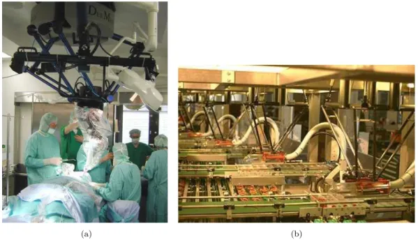
Figure I.1 – (a) SurgiScope in action at the Surgical Robotics Lab, Humboldt-University at Berlin (b) Demaurex’s Line-Placer installation for the packaging of pretzels in an industrial bakery
Exit point Anchor point Fixed frame Pulley Control board Cable End-effector Motor
Figure I.2 – CDPR composition : CREATOR prototype (Courtesy of LS2N, Nantes, France)
application. Some CDPRs present light-weight end-effectors and others carried out
large and heavy platforms like the Arecibo telescope [Alt02] whose end-effector
weighs 900 tons. The moving-platform is characterized by the anchor points loca-tion with respect to its gravity center. The fixed-platform is a mechanical structure that sustains the winches or the exit points. Regarding the cables, different mate-rials can be used. The cables are usually made up of steel and synthetic fibers. The
cable lengths are controlled thanks to actuation systems usually composed of a motor, a gear-head and a winch. Usually, the cable length variations are measured through proprioceptive sensors such as motor encoders.
The main advantages of CDPRs are the following :
— Large workspace : Thanks to the high cable lengths, the end-effector of CDPRs can reach larger range of motions comparing to parallel robot with rigid links.
— High dynamics : CDPRs are able to generate trajectories with high velocities and high accelerations, thanks to the low mass in motion. For example, the
FALCON manipulator [K+95] attains a peak speed of about 13 m/s, and a
peak acceleration of 43G.
— Large payload capacity : CDPRs are able to carry heavy payloads. As
shown by the CoGiRo prototype [LG13], the payload capability of the cable
robot can reach up to 500 kg, while the total mass of the moving components of the prototype is about 100 kg .
— High energy efficiency : CDPRs have higher energy efficiency than serial and conventional parallel robots.
For serial robots, an actuator bears the weight of the ulterior links and actua-tors in addition to the payload. These facts result in high energy consumption. For conventional parallel robots, the fact that the actuator payloads can be
sha-red by links makes their energy efficiency higher than serial robots [LB01]. The
energy consumption of CDPRs is concentrated on the motion of the moving-platform and the payload. It is shared by the number of the lightweight cables, leading to very low energy consumption and high payload-to-weight ratio — Low cost : A CDPR has usually a simple architecture, mainly composed
of cheap and simple mechanical components. These components are usually standard, having a low production cost. Let’s take the example of the low
cost FASTKIT4 prototype, which manifests in a mobile CDPR providing fast
picking and kitting operations [RLMGC18a].
— Simple structure : CDPRs are known by their simple structure. The assem-bly and disassemassem-bly of these manipulators are easy. Moreover, some CDPRs are reconfigurable, so that they can easily modify the position of the
ment points. Reconfiguration planning is proposed to provide the
reconfigura-tion of some cable manipulators, e.g. the CAROCA prototype [GCGG15].
— Good safety : Safety fulfillments are taken into consideration for most of CDPR applications, so that these manipulators can be used in delicate fields. For example, the robot String-Man was used at Fraunhofer IPK (Berlin,
Ger-many) for gait-rehabilitation with focus on safety considerations [SB04]. The
robot family Marionet, at INRIA in France, is used for rescue and person
as-sistance [Mer08]. In addition, CDPRs are used for some entertainments while
integrating safety mechanisms [CN12, TSPE15].
Nevertheless, existing CDPRs have some drawbacks such as low static accuracy due to static deflection and bad dynamic accuracy due to trajectory tracking errors, settling time and vibrations.
I.1.1
Redundant and non-redundant CDPRs
According to [Pot18b], CDPRs can be classified with respect to the number
of cables n and the controllable DOF of the end-effector m. This classification is based on the Degree-Of-Redundancy (DOR) r = n − m, allowing to distinguish between redundant and non-redundant cable robots.
(a) (b)
Figure I.3 – Schematics of (a) Redundant, (b) Non-redundant CDPR
I.1.1.1 Non-redundant CDPR
A CDPR is non-redundant when its DOR r = 0. Here, the number of cables is equal to the number of the controlled DOF, leading to a square wrench
ma-trix5. As a result, the cable tension vector is obtained as a function of the external
wrench exerted on the moving-platform as long as the wrench matrix is not sin-gular. Figure I.3(a) presents an example of a 3-DOF CDPR with 3 cables, where the end-effector is considered as a point-mass. It is a non-redundant CDPR. Dif-ferent applications are proposed based on non-redundant configurations of CDPRs.
For instance, the first RoboCrane demonstrator Nist [BAD+94], which is a
non-redundant CDPR with 6 cables. In [XCCJ10], a 6-DOF CDPR with 6 cables was
also discussed.
I.1.1.2 Redundant CDPR
A CDPR is redundant when n > m, i.e. r > 0. The redundancy, or the use of more actuated cables than DOF, presents many interests for CDPRs. It makes it possible to increase the ratio between the CDPR workspace and the
to-tal structure volume [Mer12, VvdWH12]. The use of a number of cables higher
than the minimum one makes it possible to customize the shape and the size of the workspace. This permits the robot acquire more robustness against failure in single drive-trains, which is highly required for applications with high demands of
safety such as rescue operations [Pot18b]. Also, the use of more cables than DOF
increases the capability of the CDPR to carry heavier payloads.
Figure I.3(b) presents an example of a 6-DOF CDPR with 8 cables. It is a redundant CDPR with 2-DOR. Numerous redundant CDPRs are discussed in
lite-rature such as the 1-DOR CDPR with 7 cables Segesta-7 [HFM+05]. The Falcon
was proposed by Kawamura [K+95]. It is a redundant CDPR with 7 cables and 6
DOF, dedicated to pick-and-place applications. It should be noted that the wrench matrix of a redundantly actuated CDPR is not square and, as a consequence, cannot be inverted. Therefore, some tension distribution algorithms have been pro-posed in the literature in order to determine the cable tension vector for a given moving-platform pose as a function of the external wrench applied to the latter
[FFT+04, PBM09, Pot14, GG11, BJS+09, YCD16].
5. The wrench matrix is a function of the end-effector pose and maps the cable tension vector into the wrench applied by the cables to moving-platform.
I.1.2
Suspended and fully-constrained CDPRs
CDPRs can be also classified according to the cable arrangement and spatial layout into fully-constrained and suspended robots.
(a) (b)
Figure I.4 – Schematics of (a) Suspended, (b) Fully-constrained CDPR
I.1.2.1 Fully-constrained configuration
According to the arrangement of the cables, a necessary condition for a CDPR to be in a fully-constrained configuration is when at least one driven cable is below the end-effector. For horizontally planar applications, the CDPR is considered fully-constrained as the gravity has no effect on the end-effector. Here, the support of the plane balances the weight of the end-effector. Fully-constrained CDPRs were
discussed several times in literature [BKT15, Dia15]. We have the example of the
Falcon [K+95], the IPAnema [PMV10], the Segesta [HFM+05, FFT+04], etc.
I.1.2.2 Suspended configuration
The driving cables of a suspended CDPR are all present above the moving-platform. In this configuration, the gravity is considered as a virtual cable to maintain the equilibrium. This configuration was discussed in different research
works [AC15, AA02, XCCJ10]. Some famous applications adopt the suspended
configuration such as the CoGiRo [LG13], the FAST [DQZZ09, Hui15], the CableV
[HW06], etc. The arrangement of cables of a suspended CDPR leads to less risks
of interference of the cables with each other or with the environment than for the fully-constrained configuration. Moreover, as the cables are above the end-effector, the payload is shared by each cable. This allows the suspended CDPR to have
a better payload capacity. A weakness of suspended CDPRs is that they present weak stiffness along horizontal directions. This may lead to instability and vibra-tions under the effect of external disturbances, especially while using a light-weight end-effector.
I.1.3
Applications
CDPRs are used in different fields of applications. They can be appropriate to tasks where traditional robots are not able to provide because of their low ability to carry loads and the limitation of their workspace. Some relevant fields of applications for CDPRs are presented thereafter.
I.1.3.1 Production engineering
CDPRs succeeded in the field of production especially for painting, sand
blas-ting [GCGG16] and assembly operations. Some production processes require the
positioning of specific equipments through a large workspace or products like buil-dings, ships or airplanes. Therefore, the use of CDPRs for painting aircrafts was
suggested by the research project CableBOT [cab]. The assembly of collectors in
solar-thermal power plants was provided by the IPAnema CDPR (Fig. I.5(a)). This
was studied and evaluated in [PMV10] based on the international standard
ISO-9283. This project was shown at Automatica 2010 trade fair, Munich, Germany
(Fig. I.5(b)). In [ABVA09], the large cable delta robot (LCDR) is introduced. It
manifests in a CDPR dedicated to automated machining of large workpieces and material handling.
I.1.3.2 Logistics
The advantage of having a large workspace and high dynamics makes the CD-PRs suitable for handling, sorting, and palletizing. The idea of building ultra-high speed pick-and-place CDPRs was addressed by Kawamura in 90s through the
FAL-CON robot [K+95]. Besides, a cable robot system was addressed in [COR14] for
the transport of persons across a river. The CoGiRo prototype [LG13] ensures
handling of boxes in automatic operations. It can carry up to 500 kg. Besides, the
FASTKIT project [RLMGC18b] dealt with a low cost and versatile robotic
(a) (b)
Figure I.5 – Cable robot IPAnema 2 : (a) Vision of assembly of parabolic re-flector panels [PMV10] (b) Large-scale handling of collector modules shown at Automatica 2010 trade fair, Munich, Germany [Pot18a]
prototype addresses an industrial need for fast picking and kitting operations in existing storage facilities.
I.1.3.3 Rescue and Rehabilitation
Thanks to cable flexibility and their low mass on motion, CDPRs are suitable
for some rescue tasks. In [TVHT99], a CDPR dedicated to rescue operations after
natural disasters as earthquakes was proposed. Later on, the robot family Marionet, at INRIA in France, is proposed for rescue and person assistance requirements
[MD10, Mer08]. Practical tests were performed with these manipulators for lifting
elderly and disabled humans in an ambient assisted living environment.
CDPRs are also used for rehabilitation [RABG07]. The force control of these
manipulators allows to reduce the effective mass and then to comfort the pa-tient from the weight of some parts of his body during the exercise. A gait-rehabilitation CDPR, implemented at Fraunhofer IPK (Berlin, Germany), was
pro-posed in [SB04]. CDPRs are also used for arms [ADG+09, RGM07, GCRS15] and
Figure I.6 – The cable robots of the Marionet family : Courtesy of INRIA Sophia-Antipolis, France
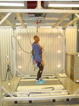
Figure I.7 – The cable robot String-Man : Courtesy of Fraunhofer IPK, Berlin I.1.3.4 Acquisition
Numerous CDPRs, whose end-effector is dedicated for measurements by
equip-ping it with camera or any other sensor, are proposed. In [JKKS98, JKK99], a
CDPR is proposed for measuring the end-effector pose along a trajectory. Some
projects such as FAST [DQZZ09, Hui15] and Carlina [LCDA+04] use CDPRs to
guide huge telescopes. Some CDPRs are employed as aerial cameras at sport or
en-tertainment events like Skycam [Con85] and CableCam [RB93], whose end-effectors
are cameras. Thanks to their large workspace, these robots are usually used in sta-diums or for movie shooting.
I.1.3.5 Construction
The flexibility of cables allows CDPRs to be used in building construction
through suitable geometrical configurations. The project MEDIA-TIC [Bes16] was
proposed to establish an intelligent building. For this purpose, a CDPR whose end-effector is equipped with atmospheric sensors is integrated in the building facades
[IGB+13]. In [IDH+18], a CDPR dedicated to construction by means of additive
manufacturing is discussed. This manifests in the mount of the extruder of the
Py-los project [Pyl] on the Cogiro robot [GCRB15] to obtain a large scale 3D printing
machine for construction tasks.
Figure I.8 – Cogiro, Pylos and the high print being processed [IDH+18]
I.1.3.6 Entertainment
CDPRs are also used for entertainment. They can be implemented in amusement
parks such as Disney [CN12], which has thrill rides based on suspended CDPRs.
The principle of these attractions is the following : People sit inside a vehicle, which presents the CDPR moving-platform. This latter is connected to the base through moving winches along roller coaster rails (Fig. I.9(a)). At the German Pavilion, at
the EXPO 2015 in Milan, two large-scale CDPRs [TSPE15] were installed whose
end-effectors were flying above the heads of the visitors (Fig. I.9(b)). Each robot consists of a mobile platform suspended by eight cables and following a prescribed trajectory. In all those activities, safety requirements are guaranteed.
(a) (b)
Figure I.9 – (a) Concept for a thrill ride with winches moving along a track (b) Two large-scale cable robots are core elements of the show at the German pavilion on the Expo 2015 fair in Milan, 2015 [TSPE15, Pot18b].
I.2
Pose accuracy
The improvement of the robot performances can be done through the
modifi-cation of the robot structure either by optimizing the design [ADG+09, XCCJ10,
GCG+14, YTWH10] or by adding other components to the robot structure as
in [VP15, WCG14]. Improving accuracy is still possible once the robot is
ope-rational through a suitable control scheme. Numerous control schemes were pro-posed to enhance the CDPRs precision on static tasks or on a trajectory
tra-cking [JFGK15, FFT+04, ZDDB08, dRRK18]. See that the response of a cable
robot depends strongly on its overall stiffness, including the stiffness of its cables. The effectiveness of a control strategy depends strongly on the choice of the robot model, including the modeling of cables stiffness.
I.2.1
Modeling
The development and the design of controllers for CDPRs require the establish-ment of accurate models of the cable manipulators. This depends on the considered properties of the robot cables with respect to the overall CDPR size. CDPRs mo-dels can be classified based on the considered cables stiffness. Two classes of cables stiffness are defined : (i) The axial stiffness of the cables associated with the elastic material modulus and the cable structure ; and (ii) the sag-introduced flexibility coming from the effect of cable weight onto the static cable profile.
the consideration of the sag-introduced stiffness is important. In statics, numerous
works describe the sag effect through the catenary model of cables [Irv92, YLZ13].
The modeling of CDPRs with long cables whose stiffness depends on the sagging
effect and on cable tension is treated in [Li15]. More recently, [Ars13a] and [YCD15]
studied the effect of the elasto-sagging of cables on the CDPR stiffness. A good correlation between experimental results and theoretical ones was highlighted in
[YCD15], validating the elasto-sagging model for static stiffness modeling. CDPR
modeling can be also provided by finite-element models. An accurate representation
of the oscillatory behavior of the CDPR was shown in [DDB13] through
finite-element analysis. The limitation of this method is that repeated mesh generations and calculations for numerous payload directions are time-consuming, which is not convenient for dynamic tasks.
The lumped-mass model can also be used as a method of modeling flexible
CDPRs. A spatial CDPR with sagging cables was modeled in [LNC07]. As an
alternative, a similar lumped-mass model, considering the actuator dynamics and
the wrap around the winch, is proposed in [CF14, CFM15]. However, these models
are valid only when working in a reduced workspace, in which there is no contact between lumped masses and the winches. Besides, to accurately achieve the true cable natural frequencies, many lumped masses are needed.
The Rayleigh-Ritz method can also be used to develop an accurate model of
cable manipulator. The work of [GCF18] uses this method to describe the
longi-tudinal vibrations of cables, a way to make this model useful for controller design. It highlights the importance of using this method rather than the lumped-mass methods.
A simpler way to model CDPRs is to consider cables as linear springs, whose
stiffness is inversely proportional to the cable lengths [KT14, WCG15]. When the
moving-platform of a CDPR with a relatively small overall size is suspended by tensed cables and balanced by the gravity, the full stiffness of the cables may
be generalized to only axial flexibility [BCCD17]. This latter manifests in cable
elongations.
I.2.2
Error sources affecting accuracy
All models are approximations and the parameters used into a CDPR given model are subjected to uncertainties. The mathematical models do not perfectly