HAL Id: tel-00586081
https://tel.archives-ouvertes.fr/tel-00586081
Submitted on 14 Apr 2011HAL is a multi-disciplinary open access archive for the deposit and dissemination of sci-entific research documents, whether they are pub-lished or not. The documents may come from teaching and research institutions in France or abroad, or from public or private research centers.
L’archive ouverte pluridisciplinaire HAL, est destinée au dépôt et à la diffusion de documents scientifiques de niveau recherche, publiés ou non, émanant des établissements d’enseignement et de recherche français ou étrangers, des laboratoires publics ou privés.
Jin Zhao
To cite this version:
Jin Zhao. Contribution to intelligent vehicle platoon control. Other. Ecole Centrale de Lille, 2010. English. �NNT : 2010ECLI0010�. �tel-00586081�
No d’ordre : 1 2 9
ÉCOLE CENTRALE DE LILLE
THÈSE
présentée en vue d’obtenir le grade de
DOCTEUR
Spécialité : Automatique et Informatique Industrielle par
ZHAO Jin
Doctorat délivré par l’École Centrale de Lille
Contribution à la Commande d’un Train
de Véhicules Intelligents
Soutenue le 2 septembre 2010 devant le jury :
Rapporteurs: Prof. Abdellah EL MOUDNI UTBM - Montbéliard
Prof. Claude H. MOOG Directeur de Recherche, EC Nantes Prof. Shaoping WANG Beihang University - Pékin, Chine Examinateurs: Prof. Philippe BONNIFAIT UTC - Compiègne
Prof. Pierre BORNE EC Lille
Prof. Abdelkader EL KAMEL EC Lille / Directeur de thèse
Dr. El Miloudi EL KOURSI Directeur de Recherche à l’INRETS - Lille
Thèse préparée au Laboratoire d’Automatique, Génie Informatique et Signal L.A.G.I.S.- École Centrale de Lille
Serial No : 1 2 9
ECOLE CENTRALE DE LILLE
THESIS
Presented to obtain the degree of
DOCTOR
Topic : Automatic Control and Computer Engineering by
ZHAO Jin
Ph.D. awarded by Ecole Centrale de Lille
Contribution to Intelligent Vehicle
Platoon Control
Defended on September 2, 2010 in presence of the committee :
Rapporteurs: Prof. Abdellah EL MOUDNI UTBM - Montbéliard
Prof. Claude H. MOOG Research Director, EC Nantes Prof. Shaoping WANG Beihang University - Beijing, China Examiners: Prof. Philippe BONNIFAIT UTC - Compiègne
Prof. Pierre BORNE EC Lille
Prof. Abdelkader EL KAMEL EC Lille / Thesis supervisor Dr. El Miloudi EL KOURSI Research Director, INRETS - Lille
L.A.G.I.S.- Ecole Centrale de Lille
Acknowledgments
The PhD work presented in this thesis has been done at "Laboratoire d’Automatique, Génie Informatique et Signal" (LAGIS) in Ecole Centrale de Lille, from September 2007 to September 2010. This work is partly supported by the China Scholarship Council (CSC).
This thesis would not have been possible without the help and support of so many people in so many ways. I would like to take the opportunity to express my gratitude to all those who contributed to this work.
First of all, my sincere thanks go to my supervisor, Prof. Abdelkader EL KAMEL, for his valuable guidance, continuous encouragement and the share of his research experience. I would like to thank Prof. Pierre BORNE for his generous cooperation and helpful discussions and the share of his outstanding research experience. A special acknowledge-ment should be shown to Prof. Shaoping WANG, during her visiting period in LAGIS, I benefited a lot from her helpful suggestions and discussions.
I would like to express my sincere gratitude to Prof. Abdellah EL MOUDNI and Prof. Claude H. MOOG, who have kindly accepted the invitation to be the reviewers of my PhD thesis. My heartfelt thanks go to Prof. Philippe BONNIFAIT and Dr. El Miloudi EL KOURSI, for their kind acceptance to be the members of my PhD Committee.
I am also very grateful to the staff in EC Lille. Virginie LECLERCQ, Marie-Françoise TRICOT, Christine YVOZ, and Brigitte FONCEZ have helped me in the administra-tive works. Many thanks go also to Bernard SZUKALA, Hilaire ROSSI, Gilles MAR-GUERITE, Jacques LASUE, Patrick GALLAIS and Régine DUPLOUICH, for their kind help and hospitality.
I wish to express my special appreciation to Prof. Hélène CATSIAPIS, my French teacher. In her courses, I learned not only the language but also the culture, history, especially the many trips, which enrich my life in France.
I would like also to thank my colleagues and friends, Ismahène, Yahong, Minzhi, Andreea, Lian, Yifan, Pengfei, Yang, Dapeng, Jinlin, Jian, Huarong, Hui, Guoguang, Bo, Wenhua... for their friendship and supports.
Finally, my parents and my brother have provided me with their supports throughout, as always, for which my mere expression of gratitude does not suffice. Thanks to my wife, Ting, for her love, understanding and great patience during the past 3 years, even if that meant sacrificing the time we spent together. Thanks to my son, Pengpeng, for all the joy and happiness he brings to me.
Contents
List of Figures xiii
List of Tables xvii
Acronyms xix
General Introduction 1
Chapter 1 Automated Highway System & Intelligent Vehicle Control 7
1.1 Background . . . 7
1.2 ITS & Automated Highway System . . . 9
1.2.1 What’s ITS? . . . 9
1.2.2 What does Automated Highway System stand for? . . . 10
1.2.3 Intelligent vehicle . . . 12 1.3 Previous research . . . 14 1.3.1 Research projects . . . 14 1.3.1.1 Projects in U.S. . . 14 1.3.1.2 Projects in Asia . . . 15 1.3.1.3 Projects in Europe . . . 16
1.3.2 Control architecture for a vehicle platoon in AHS . . . 18
1.3.3 Longitudinal control . . . 19
1.3.4 Lateral control . . . 22
1.3.5 Integrated longitudinal and lateral control . . . 24
1.4 Conclusion . . . 25
Chapter 2 Modeling of Four Wheeled Vehicles for AHS 27 2.1 Introduction . . . 28
2.2 Principle movements of vehicle & decoupling of longitudinal and lateral
models . . . 29
2.2.1 Principle movements of vehicle . . . 29
2.2.2 Decoupling of longitudinal and lateral models . . . 30
2.3 Modeling of Longitudinal Vehicle Dynamics . . . 31
2.3.1 Longitudinal dynamics . . . 31
2.3.1.1 Simple vehicle model . . . 31
2.3.1.2 Longitudinal tyre force . . . 32
2.3.1.3 Aerodynamic forces . . . 33
2.3.1.4 Rolling resistance . . . 34
2.3.1.5 Normal tyre force . . . 35
2.3.1.6 Effective tyre radius . . . 36
2.3.2 Powertrain dynamics . . . 38
2.3.2.1 Engine model . . . 38
2.3.2.2 Torque converter . . . 39
2.3.2.3 Gearbox . . . 40
2.3.2.4 Drive shaft, Final drive & Differential . . . 44
2.3.2.5 Braking system modeling . . . 45
2.3.3 Longitudinal model for simulation . . . 46
2.3.3.1 Assumptions . . . 46
2.3.3.2 Longitudinal model . . . 47
2.3.4 Simulations . . . 49
2.4 Modeling of Lateral vehicle dynamics . . . 51
2.4.1 Lateral kinematic model . . . 51
2.4.2 Lateral dynamic model . . . 54
2.4.3 Simulations . . . 60
2.4.3.1 Kinematic model simulations . . . 60
2.4.3.2 Dynamic model simulations . . . 60
2.5 Conclusion . . . 61
Chapter 3 Longitudinal Control for Vehicle Platoons 63 3.1 Introduction . . . 64
3.2 Architecture of longitudinal control system . . . 65
3.3 Upper level control . . . 66
3.3.2 String stability . . . 68
3.3.2.1 Definition of string stability . . . 68
3.3.2.2 String stability in vehicle following system . . . 69
3.3.3 Traffic flow stability . . . 71
3.3.3.1 Definition of traffic flow stability . . . 72
3.3.3.2 Effect of spacing policy on traffic flow stability . . . 73
3.3.4 Evaluation of the Constant Time Gap spacing policy . . . 74
3.3.4.1 The Traditional Constant Time-gap (CTG) Spacing Policy . . . 75
3.3.4.2 String stability of CTG . . . 75
3.3.4.3 Traffic flow stability of CTG . . . 78
3.3.5 Proposed Safety Spacing Policy . . . 78
3.3.5.1 String stability of SSP . . . 80
3.3.5.2 Traffic flow stability of SSP . . . 83
3.3.5.3 Traffic flow capacity comparison between SSP & CTG 84 3.3.6 Simulation tests . . . 86
3.4 Lower level control . . . 89
3.4.1 Introduction . . . 89
3.4.2 Coordinated Throttle and Brake Fuzzy Controller . . . 90
3.4.2.1 Coordinated Throttle and Brake Fuzzy Control Sys-tem Architecture . . . 90
3.4.2.2 Throttle and Brake Fuzzy Controllers . . . 91
3.4.2.3 Switch Logic Between Throttle and Brake . . . 94
3.4.3 Simulation tests . . . 96
3.4.3.1 Longitudinal vehicle model for simulation . . . 97
3.4.3.2 Horizontal road condition . . . 97
3.4.3.3 Inclined road condition . . . 100
3.5 Conclusion . . . 101
Chapter 4 Vehicle Lateral Control 105 4.1 Introduction . . . 106
4.2 Methodology-Multiple model approaches . . . 109
4.2.1 Introduction . . . 109
4.2.2 The operating regime approach& multiple model/controller approach110 4.2.2.1 Framework of operating regime approach . . . 110
4.2.2.2 Dilemma between local and global . . . 111
4.2.2.3 Combination of local models and controllers . . . . 111
4.2.2.4 Conclusion of multiple model approach . . . 115
4.3 Architecture of lateral control system . . . 115
4.4 Analysis of vehicle lateral dynamics . . . 117
4.4.1 Bicycle Model . . . 117
4.4.2 Open-Loop Response to the Parameter Variations . . . 117
4.5 Lateral controller design . . . 119
4.5.1 PID with anti-windup . . . 120
4.5.1.1 Traditional PID controller . . . 120
4.5.1.2 PID with Anti-Windup . . . 122
4.5.2 Fuzzy control for vehicle steering . . . 124
4.5.2.1 Vehicle lateral model . . . 126
4.5.2.2 Input and output variables . . . 126
4.5.2.3 Fuzzy control rules . . . 126
4.5.2.4 Simulation tests . . . 126
4.5.3 Multi-model fuzzy control . . . 128
4.5.3.1 Decomposition of the operating regime . . . 129
4.5.3.2 Multi-model fuzzy controller design . . . 130
4.5.4 Virtual desired trajectory for lane change maneuver . . . 133
4.6 Simulation tests . . . 134
4.6.1 Test 1: Lane keeping control at different speeds (1) . . . 135
4.6.2 Test 2: Lane keeping control at different speeds (2) . . . 135
4.6.3 Test 3: Lane keeping control under different loads and Cornering Stiffness . . . 137
4.6.4 Test 4: Lane changing scenarios at different speeds . . . 137
4.6.5 Test 5: Lane changing scenarios under different loads and Cornering Stiffness . . . 140
4.7 Conclusion . . . 141
Chapter 5 Global Control System Design-Integration of Longitudinal and Lateral Controllers 143 5.1 Introduction . . . 143
5.2 System integration . . . 144
5.2.2 Integrated longitudinal and lateral control system . . . 144
5.3 Simulation experiments . . . 146
5.4 Conclusion . . . 147
Chapter 6 Observation of Vehicle States and Multi-Sensor Intelligent Ve-hicle Prototype 151 6.1 Introduction . . . 152
6.2 Observation of vehicle states . . . 152
6.2.1 Introduction . . . 152
6.2.2 Kalman-Bucy Filter for LTV system . . . 154
6.2.3 Yaw rate and lateral velocity estimation using Kalman-Bucy filter . 155 6.2.4 Estimation results . . . 158
6.3 Presentation of reduced scale multi-sensor intelligent vehicle prototype . . 159
6.3.1 Technologies . . . 159
6.3.1.1 Multi-sensor system . . . 159
6.3.1.2 The microcontroller . . . 163
6.3.1.3 Wireless communication . . . 163
6.3.2 Integration . . . 164
6.3.3 Control strategies and first tests . . . 164
6.4 Conclusion . . . 164
Conclusions and Perspective 167
Résumé étendu en français 171
List of Figures
1.1 World motor vehicle production . . . 8
1.2 Intelligent Transportation System (ITS) illustration . . . 10
1.3 Vehicle platoon in the NAHSC demonstration . . . 15
1.4 ITS development chronology in the world . . . 18
1.5 Hierarchical architecture for automated driving . . . 19
1.6 Two-level structure for longitudinal control . . . 20
2.1 Six degrees of freedom vehicle model . . . 29
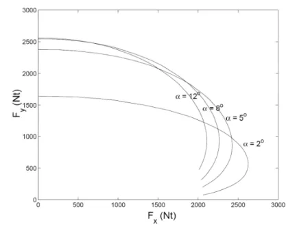
2.2 Friction ellipse represents the interdependence of longitudinal and lateral forces for several constant value of the slip angle . . . 31
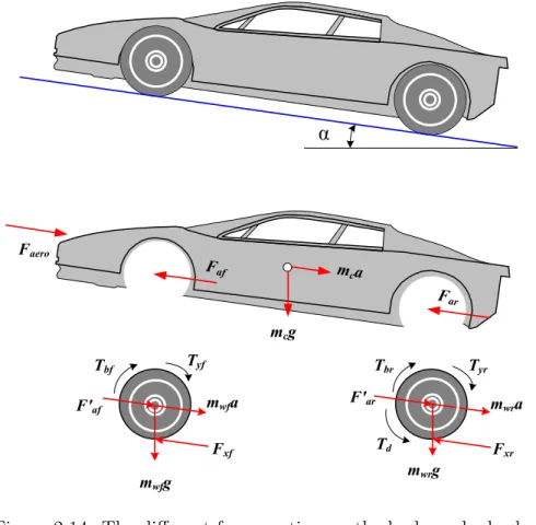
2.3 Vehicle on a inclined road . . . 32
2.4 Longitudinal tyre force as a function of slip ratio . . . 34
2.5 Pressure distribution at a non-rotation and rotation tyre . . . 35
2.6 Calculation of tyre effective radius . . . 37
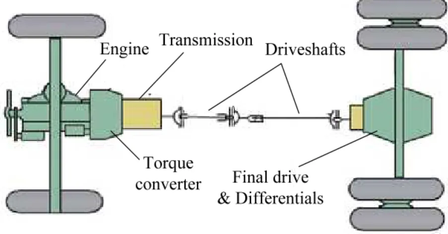
2.7 Vehicle powertrain system . . . 39
2.8 Example of engine map . . . 40
2.9 Block diagram of torque converter subsystem . . . 41
2.10 Gear shift schedule . . . 41
2.11 Model of automatic gear shift control . . . 42
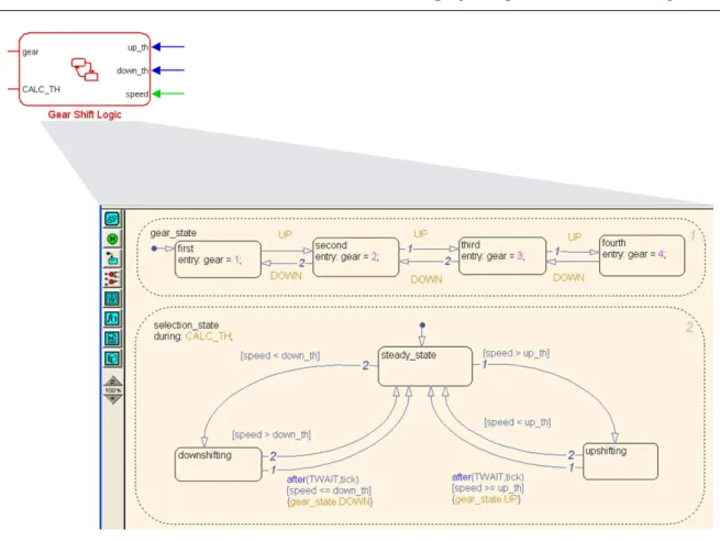
2.12 Stateflow diagram of the gear shift logic . . . 43
2.13 Typical braking system . . . 45
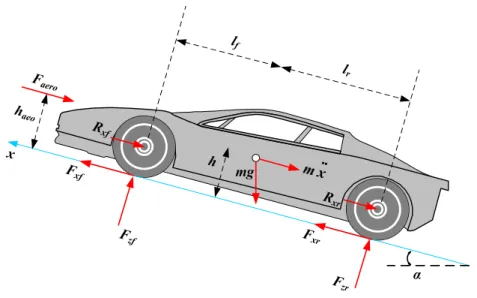
2.14 The different forces acting on the body and wheels . . . 48
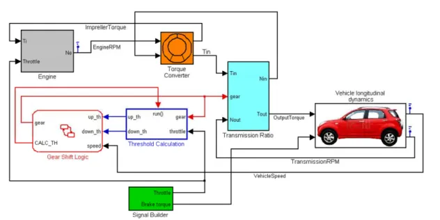
2.15 Vehicle longitudinal system diagram . . . 50
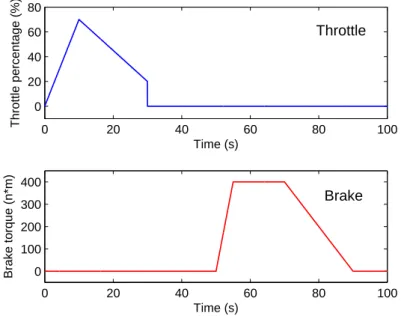
2.16 Throttle and brake input for simulation . . . 51
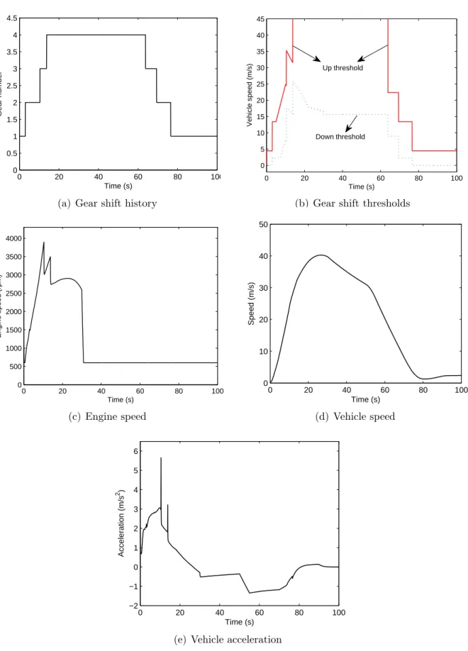
2.17 Simulation of longitudinal model . . . 52
2.18 Kinematic bicycle model . . . 53
2.19 Bicycle model for vehicle lateral dynamics . . . 55
2.20 The vehicle lateral system . . . 58
2.21 Kinematic model results with different steering angles δ . . . 60
2.22 Dynamic model results with different speeds . . . 61
3.1 Two-level structure for longitudinal control . . . 66
3.2 Vehicle platoon . . . 66
3.3 Fundamental diagram . . . 71
3.5 Vehicle platoon . . . 75
3.6 Impulse response of the CTG system . . . 77
3.7 Inter-vehicle spacing with different safety coefficients γ . . . 80
3.8 Impulse responses at different velocities of the SSP system . . . 83
3.9 Q − ρ curves of the CTG and SSP . . . 84
3.10 Single lane highway . . . 85
3.11 Q − v curves of CTG and SSP . . . 86
3.12 Results of longitudinal control . . . 88
3.13 Coordinated throttle and brake control system diagram . . . 90
3.14 Variables of fuzzy throttle controller . . . 93
3.15 Block diagram of logic switch . . . 94
3.16 Switching regions and conditions . . . 95
3.17 Flowchart of switch logic . . . 96
3.18 Longitudinal car model . . . 97
3.19 Leading vehicle’s speed and acceleration . . . 98
3.20 Following vehicle’s speed and speed error . . . 99
3.21 Inter-vehicle spacing and spacing error . . . 99
3.22 Control results of throttle and brake (horizontal road) . . . 100
3.23 Road grade, speed error and spacing error (inclined road) . . . 102
3.24 Control results of throttle and brake (inclined road) . . . 103
4.1 Road fatalities in U.S.A. . . 106
4.2 Multiple model/controller approach . . . 110
4.3 Decomposition of a complex system . . . 111
4.4 Hierarchical decomposition of a complex system . . . 112
4.5 Approximation methods for local models . . . 112
4.6 Hard partitions example . . . 113
4.7 Fuzzy membership functions of LOW and HIGH . . . 114
4.8 Hierarchical architecture for vehicle lateral control . . . 116
4.9 Open-loop responses to parameter variations . . . 119
4.10 Block diagram of PID controller . . . 120
4.11 P control system . . . 121
4.12 Step response of PID controller after the first tuning . . . 122
4.13 Step response of PID controller after the fine-tuning . . . 122
4.14 PID controller with saturation constraint . . . 123
4.15 PID controller with Anti-Windup . . . 124
4.16 PID with anti-windup control system: step responses at different speed . . 124
4.17 Simple bike model . . . 125
4.18 Membership functions . . . 127
4.19 Traditional fuzzy controller: step responses at different speeds . . . 128
4.20 Decomposition of operating regimes . . . 131
4.21 Lateral controller: Multi-model fuzzy controller block diagram . . . 131
4.22 Variables in multi-model fuzzy controller . . . 132
4.23 Trapezoidal acceleration profile . . . 133
4.25 Desired trajectory (1) . . . 136
4.26 Lane keeping control results at different speeds (1) . . . 136
4.27 Desired trajectory (2) . . . 138
4.28 Lane keeping control results at different speeds (2) . . . 138
4.29 Lane keeping control results under different loads . . . 139
4.30 Virtual Desired Trajectory . . . 140
4.31 Lane changing control results at different speeds . . . 140
4.32 Lane changing control results under different loads . . . 141
5.1 Uncoupled longitudinal and lateral control system . . . 144
5.2 Integrated control system . . . 145
5.3 Speed and road profiles . . . 147
5.4 Longitudinal control results . . . 149
5.5 Lateral control results . . . 150
6.1 Bicycle model for vehicle lateral dynamics . . . 156
6.2 Steering angle input and vehicle longitudinal velocity . . . 160
6.3 Measured and estimated lateral acceleration . . . 160
6.4 Estimation results . . . 160
6.5 Two-car platoon . . . 161
6.6 Multi-sensor system . . . 162
6.7 Magnetic field . . . 162
6.8 Platoon communication system . . . 163
List of Tables
1.1 Potential benefits of AHS . . . 11
1.1 Potential benefits of AHS . . . 12
3.1 Parameters for longitudinal controller . . . 80
3.2 Platoon vehicles’ braking capacities (m/s2) . . . 87
3.3 Fuzzy Rule Base . . . 92
4.1 Nomenclature of Bicycle Model . . . 118
4.2 Ziegler-Nichols tuning rule based on critical gain Kcr and critical period Pcr (Second Method) . . . 121
4.3 Fuzzy Rule Base . . . 128
4.4 Membership Function Variables . . . 133
4.5 Fuzzy Rule Base . . . 133
4.6 Parameter Variations . . . 139
5.1 Parameters for longitudinal controller . . . 146
Acronyms
ACC - Adaptive Cruise ControlAHS - Automated Highway System
CTG - Constant Time-Gap spacing policy
LTI - Linear Time Invariant
LTV - Linear Time Variant
SSP - Safety Spacing Policy
General Introduction
The research presented in this thesis addresses the longitudinal and lateral control strate-gies for intelligent vehicles in highway, with the main aims of alleviating traffic congestion and improving traffic safety. The background of this research is the significant develop-ment of automobile industry in the past decades, which makes the automobiles play an important role in the evolution of industry and even of our society. However, the traffic problems such as traffic congestion, safety, pollution and fuel consumption are becoming more and more serious all over the world. To cope with these problems and to achieve the goal of “Sustainable Mobility”, the conception of AHS (Automated Highway System) has been proposed, in which, vehicles can travel together in tightly spaced platoons. In the past two decades, researches on AHS have seen significant progresses. As one of the most active research topics in AHS, the longitudinal and lateral control for automated vehicles is currently being studied by researchers and automotive manufactures.• Longitudinal control
Vehicle longitudinal control system provides assistance to the driver in the task of longitudinal control by using automatic throttle and brake controllers. The first generation of longitudinal control systems like ACC system (Adaptive Cruise Con-trol system) are primarily being developed for improving driving comfort with some potential in increasing vehicle safety. However, the impacts of these systems on highway traffic have been inadequately studied [Swaroop 1999]. In this work, the longitudinal controller design is considered for the operations of vehicle platoon. Thus, we need to consider not only the requirements of driving comfort and vehicle safety but also the challenges of string stability, traffic flow capacity and stability, etc. To meet these challenges, the structure of the longitudinal control system is generally designed to be hierarchical, with an upper level controller and a lower level controller. The upper level controller determines the desired acceleration or speed for the controlled vehicle, while the lower level controller decides the required throttle and brake commands to track the desired acceleration or speed.
The principle design tasks in the upper level control include the design of spacing policy and its associated control algorithm. The spacing policy plays an important role in vehicle longitudinal control because it has great influences on vehicle safety and traffic capacity. In this work, a safety spacing policy (SSP) is proposed, which is a nonlinear function of vehicle velocity. It uses both the information of vehicle’s state and braking capacity to adjust the position and velocity of the controlled vehicle. Furthermore, the special efforts are devoted to the analysis of the string stability, traffic flow capacity and stability of the proposed SSP. A comparison between the SSP and the traditional CTG (constant time gap) policy is also presented.
The nonlinearities and uncertainties in vehicle longitudinal dynamics are the main challenges to be met in the design of throttle and brake controllers (lower level control). For instance, the exact engine model and brake system dynamics are always complex nonlinear models with numerous parameters. And in most cases, these models are hard to get. Another difficulty is that the throttle and brake pedals should work coordinately. To cope with these problems, a coordinated throttle and brake fuzzy control system is proposed. At first, an additive fuzzy controller is proposed to realize the throttle and brake control. The main advantage of this approach is that it can realize the accurate and smooth vehicle speed control without the knowledge of the exact engine and brake system dynamic models. Second, a logic switch is designed to coordinate the two speed actuators.
• Lateral control
As far as lateral control is concerned, the lateral control system generates steering commands to keep the vehicle running along the desired path or steer the vehicle into an adjacent lane. The design requirement of vehicle lateral control is to ensure small lateral errors and small relative yaw angles while maintaining ride comfort under different conditions. Lane keeping and lane changing are the two basic functions of lateral control system.
At first, lane keeping control is studied. The vehicle lateral dynamics is presented by the well-known “bicycle model”. Since in highway operation, the vehicle parameters such as speed, load, movement inertia, wheel cornering stiffness, may vary in a wide range. The lateral model is thus a LTV (Linear Time Variant) model with parameter uncertainties. A multi-model fuzzy controller is proposed for the lane keeping operation. The proposed solution combines the strong points of multi-model and fuzzy approaches. It can provide stable performances during the whole
range of operation speed, and it can also repel the system uncertainties in vehicle load, movement inertia, wheel cornering stiffness, etc.
Second, the main difficulty in the lane changing maneuver is that the vehicle must travel a certain distance without sensor feedback if the onboard sensors can not mea-sure vehicle’s location between the adjacent two lanes, for instance, if the magnet-magnetometer sensing system is employed. The virtual desired trajectory (VDT) is then introduced for the lane changing maneuver. By using VDT, the lane changing operation is then investigated as a lane keeping problem. In order to effectuate flex-ible switch between different lateral operations, such as lane keeping, lane changing, overtaking, and etc, a hierarchical architecture is then proposed for vehicle lateral control system.
Based on the given results in both longitudinal and lateral control, we propose a global control system, which integrates the designed longitudinal and lateral control systems, to realize the final goal of automated vehicle control.
In addition, the vehicle state estimation is also studied as a step towards the applica-tion of the proposed vehicle controllers. Since in the controller design process, the required vehicle states are always assumed to be available. However, in practice, this assumption is not always correct. Then the vehicle state observer is required. Considering the sensor system configuration and the required states for the vehicle controllers, we choose the ve-hicle yaw rate as the parameter to be estimated. Since the control plant is a LTV system, the traditional Luenberger observer is not available in this case. A Kalman-Bucy filter is then designed for the LTV system estimation.
Finally, a reduced scale (1:10) multi-sensor intelligent vehicle prototype is introduced. The different aspects of the prototype from the multi-sensor system, vehicle structure, communication system, and HMI are presented. This prototype provides a platform for advanced technology integration, reliability analysis, real time control and monitoring. In the first-step tests with the prototype, the basic functions such as vehicle following and lane tracking were realized. In the future work, the more complex scenarios will be tested.
Outline of the thesis
Chapter 1 reviews the developments in automated vehicle control. At first, the back-ground of the current traffic situation and problems are introduced. Second, ITS, AHS, and intelligent vehicle, which are considered as the most promising solutions (at different
levels) to the traffic problems, are introduced. Finally, the evaluations of the outstanding projects and the developments in vehicle longitudinal and lateral control have been sur-veyed in detail.
In Chapter 2, the vehicle longitudinal and lateral models are presented, which will be employed in the controller design in the following chapters. For the longitudinal model, at first, we establish the non-linear longitudinal dynamic model based on the New-ton’s second law, with the hypothesis of no-slip at the tyre-road interface. Second, the powertrain dynamic model of a passenger car with an automatic gearbox is built, which includes the sub-models of different parts in the powertrain system, the engine, torque converter, automatic gearbox, drive shafts, final drive and differential, as well as the braking system. By using this powertrain model, we can simulate the vehicle behavior thus to test the controllers’ performances in the following chapters.
For the lateral model, the kinematic and dynamic models are studied respectively. The kinematic model provides a mathematic description of the vehicle motion without considering the forces that affect the motion, and it considers only the geometric pa-rameters. A “bicycle” model is adopted to express the vehicle lateral dynamics. Under the assumptions of small steering angle and small slip angle, the bicycle model can be described by a 4th order linear model.
Chapter 3 concentrates on the vehicle longitudinal control system design. The lon-gitudinal control system architecture is designed to be hierarchical, with an upper level controller and a lower level controller. In the upper level controller design, a safety spacing policy (SSP) is proposed, which uses both the information of vehicle state and vehicle braking capacity to determine the desired spacing from the preceding vehicle. A comparison between the SSP and the traditional CTG (constant time gap) policy is also presented. In the lower level controller design, a coordinated throttle and brake fuzzy controller is proposed. And a logic switch is designed to avoid frequent switching between the two actuators and simultaneous operations of them. Finally, the above proposed lon-gitudinal control system is validated to be effective through a series of simulations.
Chapter 4 is devoted to the vehicle lateral control. A multi-model fuzzy controller is designed to perform lane keeping and lane changing operations. For the lane changing maneuver, the concept of VDT “Virtual Desired Trajectory” is introduced to provide a smooth and efficient lane changing trajectory. In order to effectuate flexible switch
be-tween different lateral operations, a hierarchical architecture is then proposed for vehicle lateral control system.
Chapter 5 proposes a global control system, which integrates the longitudinal and lateral control systems that we have given in chapter 3 and 4. By using this system, the vehicle longitudinal controller and lateral controller can work coordinately.
Chapter 6 discusses two aspects relating to the practice, the observation of vehicle states and the design of a reduced scale multi-sensor intelligent vehicle prototype. A Kalman-Bucy filter is introduced to estimate the yaw rate for vehicle later control. And the different aspects of the design of a multi-sensor intelligent vehicle prototype are pre-sented.
Chapter 1
Automated Highway System &
Intelligent Vehicle Control
Contents
1.1 Background . . . 7 1.2 ITS & Automated Highway System . . . 9 1.2.1 What’s ITS? . . . 9 1.2.2 What does Automated Highway System stand for? . . . 10 1.2.3 Intelligent vehicle . . . 12 1.3 Previous research . . . 14 1.3.1 Research projects . . . 14 1.3.2 Control architecture for a vehicle platoon in AHS . . . 18 1.3.3 Longitudinal control . . . 19 1.3.4 Lateral control . . . 22 1.3.5 Integrated longitudinal and lateral control . . . 24 1.4 Conclusion . . . 25
1.1
Background
With the development of the automobile industry, the world vehicle production rose sig-nificantly during the past decades. Ten million vehicles were produced worldwide in 1950,
and this number rose to 30 million in 1970. By 2008, more than 70 million vehicles were produced, see Fig. 1.1 [Freyssenet 2009, OCIA ].
0 20 40 60 80 Pr od uc tio n (m ill io n) 0 20 40 60 80 Pr od uc tio n (m ill io n) Years
Figure 1.1: World motor vehicle production
Accompanying with this augmentation, on one hand, we benefit the vehicles in dif-ferent aspects. Take Europe for instance, road transport is the largest share of intra-EU transport, which accounts for 44% of freight and around 85% of passenger transport. In addition, the annually growth rate in the above two fields are 2.8% and 1.9% respec-tively [COMMUNITIES 2006a]. on the other hand, we have to face the spreading traffic problems as traffic congestion, safety, pollution and fuel resources, etc.
Traffic congestion has been regarded as one of the most serious social and economical and environmental problems in the world. Take the Europe Union (EU) as an example, congestion costs amount to e 50 billion per year or 0.5% of Community GDP, and by 2010 this figure could go up to 1% of EU GDP [COMMUNITIES 2006b].
Concerning energy consumption and emissions, in 2002 the transport sector consumed 338 million tonnes oil equivalent (MToe) representing 31% of the total energy consumption in the EU. Road transport consumed 281 MToe, 83% of the energy consumed by the whole transport sector. Road transport CO2 emissions account for 835 million tonnes per year
representing 85% of the total transport emissions [COMMUNITIES 2006b].
Traffic safety is one of the most serious problems that impacts our daily life. According to a WHO1forecast, by 2020 traffic accidents will rank as the third biggest cause of deaths
and disability ahead of such other problems as malaria, HIV/AIDS, and war 2. In 2004,
the “Road Safety” has been selected as the theme of the year of WHO.
In the White paper of 2001, the European Commission has set the ambitious aim of halving the number of road traffic fatalities by 2010 (from 50 000 to 25 000). Much
1WHO: World Health Organization.
2The first and second causes are Ischemic heart disease and Unipolar major depression. Source:“ The Gloval Burden of Disease,” by the WHO, 1996.
1.2. ITS & Automated Highway System progress has been achieved, road fatalities in the EU-25 in 2005 were 41 247, which have been reduced by 18,1% compared with 2001. If the trend continues at the same rate, 32 500 people will die from road accidents in 2010, the EC’s goal of 25 000 deaths in 2010 will thus not be achieved. The cost of traffic accidents is around e 200 billion every year, account 2% of EU GDP [Hoeglinger 2008].
One suggestion to the traffic problems is to build adequate highways and streets. However, the fact that it is becoming increasingly difficult to build additional highway, for both financial and environmental reasons. Data shows that the traffic volume capacity added every year by construction lags the annual increase in traffic volume demanded, thus making traffic congestion increasingly worse. Therefore, the solution to the problem must lie in other approaches, one of which is to optimize the use of highway and fuel resources, provide safe and comfortable transportation, while have minimal impact on the environment. It is a great challenge to develop vehicles that can satisfy these diverse and often conflicting requirements. To meet this challenge, the new approach of “Intelligent Transportation System” (ITS) has shown its potential of increasing the safety, reducing the congestion, and improving the driving conditions. Early studies show that it is possible to cut accidents by 18%, gas emissions by 15%, and fuel consumption by 12% by employing ITS approach [Unsal 1998].
1.2
ITS & Automated Highway System
1.2.1
What’s ITS?
The origin of Intelligent Transportation System (ITS) was shown in “Futurama”, which is a concept transportation system exhibited at the World’s Fair 1940 in New York. After a long story via many researches and projects between 1980 to 1990 in Europe, North America and Japan, today’s mainstream of ITS was formed. ITS is a transport system which is comprised of an advanced information and telecommunications network for users, roads and vehicles. By sharing vital information, ITS allows people to get more from transport networks, in greater safety, efficiency, and with less impact to the environment. The principle of ITS is illustrated in Fig. 1.2. (Source: [Japanese Ministry of Land a])
ITS is actually a big system which concerns a broad range of technologies and diverse activities. According to the Action plan for the deployment of Intelligent Transport System in Europe [COMMUNITIES 2008], the six priority areas for action and related measures in the short-to-medium term are:
User Vehicles Roads Information and Telecommunications Technologies
Improving safety, Increasing traffic efficiency, improving
comfortableness, contributing to the preservation of enviroment,
creating new industries/bussiness
Figure 1.2: Intelligent Transportation System (ITS) illustration
• Optimal use of road, traffic and travel data
• Continuity of traffic and freight management ITS services on European transport corridors and in conurbations
• Road safety and security
• Integration of the vehicle into the transport infrastructure
• Data security and protection, and liability issues
• European ITS cooperation and coordination
1.2.2
What does Automated Highway System stand for?
The Automated Highway System (AHS) is one of the most important items among the diverse topics in the research of ITS. The AHS concept defines a new relationship between vehicles and the highway infrastructure. The fully automated highway systems assume the existence of dedicated highway lanes, where all the vehicles are fully automated, with the steering, brakes and throttle being controlled by a computer [Tomizuka 1993]. AHS uses communication, sensor and obstacle-detection technologies to recognize and react to external infrastructure conditions. The vehicles and highway cooperate to coordinate
1.2. ITS & Automated Highway System vehicle movement, avoid obstacles and improve traffic flow, improving safety and reducing congestion. In brief, the AHS concept combines on-board vehicle intelligence with a range of intelligent technologies installed onto existing highway infrastructure and communica-tion technologies that connect vehicles to highway infrastructure [Cheon 2002].
The potential benefits that might acquire from the implementation of AHS could be summarized in Table 1.1. Note that some of the benefits are fairly speculative, the system they would depend upon are not yet in practical application.
Table 1.1: Potential benefits of AHS
Elements Benefits
Road capac-ity
In AHS, vehicles travel in closely packed platoons can provide a highway capacity that is three times the capacity of a typical high-way [Varaiya 1993].
Safety Human error is involved in almost 93% of accidents, and in almost three-quarters of the cases, the human mistake is solely to blame [COMMUNITIES 2006b]. Only a very small percentage of accidents are caused by vehicle equipment failure or even due to environmental conditions (for example, slippery roads). Since automated systems reduce driver burden and provide driver assistance, it is expected that the employment of well-designed automated systems will certainly lead to improve traffic safety.
Weather Weather and environmental conditions will impact little on high per-formance driving. Fog, haze, blowing dirt, low sun angle, rain, snow, darkness, and other conditions affecting driver visibility and thus, safety and traffic flow will no longer impede progress.
Mobility All drivers using AHS can be safe, efficient drivers. AHS offers en-hanced mobility for the elderly, and less experienced drivers, etc. Energy
con-sumption and air quality
Fuel consumption and emissions can be reduced. In the short term, these reductions will be accomplished because vehicles travel in a more efficient manner, lesser traffic congestion occurs. In the long term, the AHS can support future vehicle propulsion/fuel designs. Land use AHS help us to use the road efficiently, thus using the land in a
efficient way.
Table 1.1: Potential benefits of AHS
Elements Benefits
Travel time saving
AHS can save travel time by reducing congestions in urban highway travel, and permitting higher cruise speed than today’s driving. Commercial
and transit efficiency
More efficient commercial operations and transit operations. Com-mercial trucking can realize better trip reliability and transit opera-tions can be automated, extending the flexibility and convenience of the transit option to increase ridership and service.
1.2.3
Intelligent vehicle
Implementation of AHS requires automatically controlled vehicles. Nowadays, automo-biles are becoming more and more “intelligent”, with increasingly equipping with elec-tromechanical sub-systems that employ sensors, actuators, communication systems and feedback control. Thanks to the advances in solid state electronics, sensors, computer technology and control systems during the last two decades, the required technologies to create an intelligent transportation system is already available, although still expensive for full implementation. According to Ralph K [Ralph 2008], today’s cars normally have 25 to 70 ECUs ( Electronic Control Unit), which perform the monitoring and controlling tasks. Few people realize, in fact, that today’s car has four times the computing power of the first Apollo moon rocket [Andrew H 1993].
Intelligent vehicle control is the vital part of the AHS applications. A variable of vehicle control systems are being developed. In our work, we will concentrate in the design of the two most basic control systems: longitudinal control and lateral control. Before introducing the state of art technologies in these two systems, we will briefly introduce some of the major electromechanical feedback control systems related to the longitudinal and lateral control, which are under developed in the automotive industry and the research laboratories.
• Adaptive Cruise Control (ACC) systems perform longitudinal control by con-trolling the throttle and brakes so as to maintain a desired spacing from the preced-ing vehicle. A significant benefit of uspreced-ing ACC is to avoid rear-end collisions. The SeiSS study reported that it could save up to 4 000 accidents in Europe in 2010 if only 3% of the vehicles were equipped [Abele 2005].
1.2. ITS & Automated Highway System • Lateral support includes Lane Departure Warning (LDW) and Lane Change Assistant (LCA) systems. The LDW system will warn the driver if his or her vehicle leaves its lane unintentionally, while a LCA will check for obstacles in a vehicle’s course when the driver intends to change lanes. The same study estimated that 1 500 accidents could be avoided in 2010 given a penetration rate of only 0.6%, while a penetration rate of 7% in 2020 would lead to 14 000 fewer accidents.
• Collision Avoidance (CA) operates like a cruise control system to maintain a constant desired speed in the absence of preceding vehicles. If a preceding vehicle appears, the CA system will judge the operation speed is safe of not, if not, the CA will reduce the throttle and/or apply brake so as to slow the vehicle down, at the same time a warning is provided to the driver.
• Drive-by-wire technology replaces the traditional mechanical and hydraulic con-trol systems with electronic concon-trol systems using electromechanical actuators and human-machine interfaces such as pedal and steering feel emulators. The benefits of applying electronic technology are improved performance, safety and reliability with reduced manufacturing and operating costs. Some sub-systems using “by-wire” technology have already appeared in the new car models.
• Vehicle navigation system typically uses a GPS navigation device to acquire position data to acquire position data to locate the user on a road in the unit’s map database. Using the road database, the unit can give directions to other locations along roads also in its database.
• Automated Vehicle Identification (AVI) and Automated Vehicle Location (AVL) systems: the AVI system was first applied for the Electronic Toll Collection (ETC) system to determine the identity of a vehicle subject to tolls. Most current AVI systems rely on radio-frequency identification, where an antenna at the toll gate communicates with a transponder on the vehicle via Dedicated Short Range Communications (DSRC). While, the AVL automatically determines the geographic location of a vehicle and transmits the information to a requester. Normally, the GPS and a radio communication system are required. As a result of AVI and AVL, processing real-time information on vehicle locations will be possible. A special application of these technologies can be found in vehicle platoon control, will be mentioned in Chapter 3.
1.3
Previous research
1.3.1
Research projects
1.3.1.1 Projects in U.S.
After the first appearance of the concept of automated driving in the 1940 World’s Faires, in the late of 1950s, RCA(Radio Corporation of America) in collaboration with the GM (General Motors) proposed the concept of Automated Highway System. The full AHS concept was initially examined by GM with sponsorship from U.S. department of Trans-portation (DOT) during the late 1970s.
With the rapid evolution of automobile and the appearance of the problems of con-gestion around the big cities, the program PATH (Partners for Advanced Transit and Highways), one of the most fruitful organization in transportation researches, was cre-ated by the Caltrans (California Department of Transportation) and ITSUC (Institute of Transportation Studies of the University of California) in Berkeley in 1986 [PATH ]. The current research projects are mainly in the following three fields:
• Transportation Safety Research
• Traffic Operations Research
• Modal Applications Research
In later 1994, the U.S. Department of Transportation launched the National Auto-mated Highway System Consortium (NAHSC). The consortium attempted to expand the programme’s expertise and resources, and contribute to the goal of fully automated highway systems.
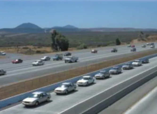
In 1997, a demonstration was conducted in San Diego by PATH programme. Eight fully automated cars traveled together in a tightly spaced platoon guided by the magnetic plots fixed on the center of the road, see Fig. 1.3. This demonstration is regarded as the first milestone of the AHS programme, and showed the feasibility of the AHS.
Although the demonstration showed that the progress had been made, the U.S. DOT withdrew financial support from NAHSC and shifted its priorities to short-term, safety oriented technology development. Also in 1997, the project Intelligent Vehicle Initiative (IVI) Programme was carried out, which is a government-industry partnership to accel-erate the development and commercialization of safety, and driver assistance systems.
1.3. Previous research
Figure 1.3: Vehicle platoon in the NAHSC demonstration
1.3.1.2 Projects in Asia
In the Asia region, road transport problems are becoming increasingly serious in the big cities because of the growth of motorization in many countries. To cope with these problems, several countries and regions begun to install electronic toll collection systems (e.g. Singapore, Malaysia, and Hong Kong). While, works on ITS have been started in other countries as well.
• Activities in Japan [Japanese Ministry of Land b]
In 1973, works on CACS (Comprehensive Automobile Traffic Control System) were initiated by the Ministry of International Trade and Industry, with the development of a route guidance system and test operations.
Since the 1980s, a number of projects had been carried out, among them some representative ones are: RACS (Road/Automobile Communication System) was carried out by the Ministry of Construction. ARTS (Advanced Road Transporta-tion Systems), in which the overall concept on advancement of road traffic through integration of roads and vehicles was structured, was pursued. Accompanying this project were various others, including SSVS (Super Smart Vehicle System) intended for the intelligent vehicle traffic system, ASV (Advance Safety Vehicle) intended for promotion of research and development of vehicle safety technologies, and UTMS (Universal Traffic Management System) aimed at development of information sys-tem as a part of social infrastructure such as traffic signal and navigation syssys-tem, and etc.
Established in 1999, the ITSC (National Intelligent Transport Systems Center of Engineering and Technology) aims at improving traffic safety and efficiency by us-ing the communication and information technologies, and it is supported by the Ministry of Science and Technology. Its current research projects cover a wide field from society science to technology: Electronic toll collection and short range com-munication, traffic data analysis, safety monitoring and early-warning technology for commercial vehicles, automated snow sweeping vehicle, policy consultation and planning, and etc.
1.3.1.3 Projects in Europe
In Europe, a number of projects have been carried out since 1970s. The development of ALI (Autofahrer Leit und Information System) was promoted in the middle of 1970s in Germany. The programme PROMETHEUS ( PROgraM for a European Traffic with Highest Efficiency and Unprecedented Safety) was implemented during 1986 and 1994, leaded by EUREKA (Europe Research Coordination Agency). Its objective was to im-prove traffic safety and the management of road transport. Contemporaneously, the programme DRIVE (Dedicated Road Infrastructure for Vehicle Safety in Europe) and DRIVE II (1989-1994) studied traffic infrastructure such as road pricing and park and ride for reducing the volume of traffic in city area. These programmes have been succeeded by the current PROMOTE (Programme for Mobility in Transportation in Europe) Pro-gramme and the Telematics Applications ProPro-gramme. In 1991, ERTICO - ITS Europe was founded, which is a multi-sector, public/private partnership pursuing the development and deployment of Intelligent Transport System and Services [ERTICO ]. More recently, the programme ADASE (Advanced Driver Assistance Systems) was promoted to improve road safety, efficiency and comfort. It provided the communication and dissemination platform between experts in the field, authorities and the public.
• Activities in France
In France, PREDIT is a programme of research, experimentation and innovation in land transport, started and implemented by the ministries in charge of research, transport, environment and industry, the ADEME (Agence gouvernementale De l’Environnement et de la Maîtrise de l’Énergie) and the ANVAR (Agence National de Valorisation de la Recherche) [PREDIT ]. Since 1990, the PREDIT has past three phases, the first phase PREDIT 1(1990-1994) was mainly devoted to techno-logical innovations in vehicles; PREDIT 2 (1996-2000) covered a wider field
includ-1.3. Previous research ing the aspects of human and society sciences and transport services organization, etc. PREDIT 3 (2002-2006) aimed at the goods transportation and energy and environment issues, as well as a diversified research on safety. More recently, the project ARCOS (Action de Recherche pour une COnduite Sécurisée) was founded in 2001, which associates different partners (universities, industries) aiming at the improvement of road safety. Now the PREDIT 4 (2008-) is currently implemented, its objective is to improve 20% of energy efficiency in 2020, priority the other trans-portation methods (no-road), develop the ecological tax, and etc.
Beside the above national research projects, many universities, institutes, and re-search centers launched also divers projects aiming at solving current traffic prob-lems. Among them, some results can be cited: the urban congestion problems have been studied by the researchers from SeT (laboratoire Systèmes et Trans-ports) in UTBM (université de Technologie de Belfort-Montbéliard), autonomous vehicle control and traffic signal control using vehicle-infrastructure communication were proposed to improve the traffic efficiency in the intersection,by F. Yan, J. Wu, and A. El Moudni, see [Yan 2009, Wu 2009]. The problems of vehicle localiza-tion and autonomous navigalocaliza-tion in the urban areas were studied by the researchers from UTC (Université de Technologie de Compiègne), the GIS-Based (Geographical Information system) localization and navigation systems ,which are adapted to the real-time applications, were proposed in [Bonnifait 2007,Bonnifait 2008]. For the au-tomated vehicles in low speed automation, divers results were given by researchers from INRETS (Institut national de recherche sur les transports et leur sécurité), see [Nouveliere 2003, Mammar 2004]. An interesting solution called “virtual draw-bar” was proposed by the AUTORIS(AUTOmatique pour la Route Intelligent et Sûret). A virtual link is supposed to build a two-car platoon [Toulotte 2006]. The issues of bus guidance in station and safe tunnel control were studied in LAGIS, see [El Kamel 2002, El Kamel 2005, El Kamel 2006]. Special efforts to improve common transport (i.e. railway, bus) safety have been made by researchers from ESTAS (Evaluation des Systèmes de Transport Automatisés et de leur Sécurité), see [EL-KOURSI 2006, EL-KOURSI 2007].
SSVS RACS IVI ITSC ASV UTMS PATH U.S.A. 1970 1980 1990 2000 ERGS AHS Japan CACS China Europe ALI PROMETHEUS DRIVE PROMOTE ERTICO-ITS France PREDIT 1, 2, 3, 4 ADASE &
Figure 1.4: ITS development chronology in the world
1.3.2
Control architecture for a vehicle platoon in AHS
The intelligent vehicles in an automated cooperative driving network have to execute several maneuvers. All the maneuvers of cooperative driving can be divided into the ele-mentary maneuvers: split, merge, follow and change lane. The control architecture design for the automated vehicles in AHS should aim at more flexible platooning of automated vehicles including smooth merging and lane changing for the compatibility for both the safety and efficiency.
In 1994, the group of PATH has proposed a four-layer control architecture. The proposed four layers are: Link, Coordination, Regulation, and Vehicle dynamics. Among them, the Link layer is on the roadside system and the other three layers are in the vehicle system [Hedrick 1994]. This four-layer constructer can be viewed as the base for the more recently proposed architectures. In 2000, R. Horowitz and P. Varaiya [Horowitz 2000], also researchers from PATH, presented a five-layer architecture, which added a Network layer to the former four-layer constructer. And it can be viewed as a continued work of the former one.
Also in 2000, a group of Japanese researchers proposed an architecture for the AVCSS (Advanced Vehicle Control and safety System), which consists of three layers: vehicle control layer, vehicle management layer, and traffic management layer [Tsugawa 2000]. This architecture has a vehicle centered structure, which will enable well-organized design of the vehicle systems.
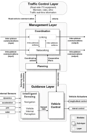
1.3. Previous research More recently, another three-layer control architecture was proposed by Simon Halle, this hierarchical architecture was inspired by Tsugawa’s architecture [Tsugawa 2000] and other concepts coming mainly from the PATH project [Lygeros 1998]. The resulting architecture has three major layers: guidance layer, management layer and traffic control layer, as indicated in Fig. 1.5. This architecture gives the more detailed descriptions to the coordination activities of the vehicles platoon, such as inter-platoon coordination and intra-platoon coordination.
Figure 1.5: Hierarchical architecture for automated driving
1.3.3
Longitudinal control
Longitudinal control and lateral control are the two basic functions of the vehicle automa-tion. Vehicle longitudinal control systems are currently being developed by researchers and automotive manufactures for highway vehicle automation [Marsden 2001,Wang 2004a, Zhou 2005]. It provides assistance to the driver in the task of longitudinal control by
us-ing automatic throttle and brake controllers. It can be classified into two categories: “autonomous”and “non-autonomous”. An autonomous system means all the required in-formation for the controlled vehicle could be gathered by on board sensors, whereas inter-vehicle communication or inter-vehicle-road communication are required for a non-autonomous system.
Regarding the longitudinal control system design, it needs to handle several chal-lenges, such as nonlinear vehicle dynamics, spacing policy and its associated control law design, string stability and traffic flow stability, as well as operation at all speed: from high-speed to a complete stop, etc. [Rajamani 2000, Santhanakrishnan 2003]. To meet these challenges, the structure of the longitudinal control subsystem is generally designed to be hierarchical, with upper and lower level controllers, see Fig. 1.6. The upper level controller determines the desired acceleration or speed for the controlled vehicle, while the lower level controller decides the throttle and brake commands required to track the desired acceleration or speed [Rajamani 2006, Zhou 2005]. Therefore, we will introduce the state of the arts technologies in the longitudinal control along the two paths.
Upper Level
Controller DynamicsVehicle
Lower Level Controller Velocity Acceleration Measured Inter-vehicle spacing Desired Acceleration Throttle or Brake + -+ -Desired Velocity
Figure 1.6: Two-level structure for longitudinal control
Lower level control
The nonlinearities and uncertainties in vehicle longitudinal dynamics are the main chal-lenges to be met in the design of throttle and brake controllers. Researches have been pursued for several decades and at many different levels by researchers and automotive manufactures. From 1970s to 1980s, there appeared some researches in the control system design for vehicle engines and brake systems, as shown in [Fisher 1970,Guntur 1972,Gun-tur 1980, Moskwa 1987, Powell 1987]. Since then, some first generation of engine control systems appeared in [Cho 1989,Grizzle 1994], and some results in the brake system control have obtained great success, such as the ABS (Anti-lock Brake System), which have been widely accepted in the automobile industry.
1.3. Previous research Based on the above results, and since 1990s, the researches in the longitudinal control combined with throttle and brake control has become steadily more attractive. Ioannou P.A. and Chien C.C. proposed a fixed gain and gain scheduling PID controllers as well as the adaptive control method for vehicle longitudinal control, see [Ioannou 1993]. The controllers were simulated using a validated full order nonlinear longitudinal model and tested also on a real vehicle, and the results are satisfied. However, in order to use these PID based controllers, an exact throttle angle to vehicle speed and position model is required as a premise. To get this model, it needs a lot of experiments to determine the required parameters and in some cases it is confidential. In [Gerdes 1997], Gerdes J.C. and Hedrick J.K. presented a combined engine and brake control system based on multiple-surface. The proposed system consists of three basic elements: an upper sliding controller that incorporates vehicle acceleration as a synthetic input, a logic switch that chooses between throttle or brake control, and lower sliding controllers for the engine and brake operations.
The fuzzy logic is also proposed for this subject. In [Naranjo 2006], Naranjo. J.E. et al. designed a throttle and brake fuzzy control system to perform the ACC+Stop&Go maneuvers. Two separate fuzzy controllers were designed to control the throttle and brake pedals. In order to avoid simultaneous actions of both the pedals, the values of the membership functions of the two controllers were well defined. The constant time gap spacing policy was used to give the desired spacing for the controlled vehicle. This system has been equipped in a two-vehicle platoon. The results showed that the automated ve-hicle behaved very similarly to human-driven car and was adaptive to the speed variations.
Upper level control
The upper level controller determines the desired acceleration or speed of the controlled vehicle. The principle design tasks in the upper level control include the design of spac-ing policy and its associated control algorithm. The spacspac-ing policy denotes the desired spacing that an automated vehicle attempts to maintain with respect to the preceding vehicle [Santhanakrishnan 2003, Wang 2004a]. In general, the desired spacing policy is a function of the vehicle velocity but could be also a constant distance or a function of other variables such as relative velocity between the controlled vehicle and the proceeding one. It plays an important role in vehicle longitudinal control system as it has great influences on vehicle safety and traffic capacity. Spacing policy and its associated control algorithm can be evaluated from the point of view of string stability, traffic flow stability and traffic flow capacity [Swaroop 1999, Santhanakrishnan 2003].
A variety of spacing policies have been proposed in early works e.g. [Shladover 1991a, Ioannou 1994,Rajamani 2000,Wang 2004a,Zhou 2005]. From the traffic capacity point of view, a constant spacing headway of about 1 m was suggested by Shladover [Shladover 1991a]. With such a tight following model, the traffic capacity increases considerably. However, it was shown that the vehicle controller needed information about the leading vehicle of the platoon to ensure string stability [Rajamani 2000, Rajamani 2006]. Therefore, an inter-vehicle communication protocol is needed to supply the information of the platoon leader to the followers. At present, the most common spacing policy used by researchers and vehicle manufactures is the constant time-gap (CTG) spacing policy [Wang 2004a]. Unlike the constant spacing policy, the tracking requirement in CTG policy can be easily obtained without any inter-vehicular communication. Much works have been done by us-ing CTG spacus-ing policy, and some manufactures have more recently launched their cruise systems based on CTG algorithms [Ioannou 1994, McDonald 1999, Marsden 2001, Nouve-liere 2003]. However, there still exists some problems in the use of CTG algorithm:
• Using the CTG policy, the current cruise control system is not suitable for use in high-density traffic conditions, and the operating speed should be higher than 40 km/h [Marsden 2001].
• Using the standard CTG policy, traffic flow stability cannot be ensured [Swa-roop 1999].
1.3.4
Lateral control
Lane departure is the number one cause of fatal accidents, and account for over 25,000 deaths annually, almost 60% of the total deaths in the highway crashes in the United States. It is also reported that the average crash rate in the curves is about 3 times that for straight segments [A.A.S.H.T.O 2008]. Vehicle lateral control systems provide a possible solution to cope with the steering problems of vehicles. It senses the road centerline using a road based reference system and other on-board sensors. Then, it generates steering commands to keep the vehicle running along the desired path or steer the vehicle into an adjacent lane. The design requirement of vehicle lateral control is to ensure small lateral errors and small relative yaw angles while maintaining ride comfort under different conditions. Lane-keeping and lane-changing are the two basic functions of vehicle lateral control system [Huang 2005].
A lane keeping system automatically controls the steering to keep the vehicle in its lane and also follow the lane as it curves around. In [Fenton 1988], Fenton R.E. and Selim
1.3. Previous research I designed a velocity-adaptive lateral controller using an optimization approach. The re-sulting controller, which is nonlinear with velocity, requires full-state feedback and thus an observer is included. In [Choi 2001], the vehicle is steered to follow the reference yaw rates which are generated by the deviations of lateral distance and the yaw angle between the vehicle and the reference lane. A PI controller was designed to minimize the error between the reference yaw rate and the measured one. In [Taylor 1999], three vision-based lat-eral control strategies: lead-lag control, full state feedback and input-output linearization were introduced and compared through a series of experiments. Although these unique model based approaches can lead to acceptable control results, their performance may be too sensitive to model mismatch and unmodeled dynamics. Besides, some controllers such as sliding mode solutions in [Zhang 2000], H-infinity controller in [Chaib 2004], and the self-turning regulator in [Netto 2004], appear rather complex for realtime embedded control of autonomous vehicles.
The lane changing system automatically steers the vehicle from the current lane to an adjacent lane. In fact, lane changing and lane keeping maneuvers become virtually identical when the lateral sensor can measure its location in both lanes. One major solution is Look-ahead lateral reference/sensing system (e.g. machine vision system). It can provide a long and wide range measurement of vehicle lateral displacement. By using this measurement, the lateral controller mimics human driver’s behavior to perform the lane changing maneuver, see [Taylor 1999, Lee 2002]. However, the reliability of machine vision system is susceptible to variations in light or inclement weather conditions. The fact that Look-down lateral reference/sensing system (e.g. magnetic markers installed in the center of highway) improves the reliability of the sensing system can be another solution. But it suffers from the small sensor range. In this case, the lane changing control problem becomes complicated as the lateral sensing system cannot sense both lanes and the vehicle must travel a certain distance without seeing the road reference system.
The virtual desired trajectory (VDT) for a lane change operation is then designed considering passenger’s ride comfort and transition time. Four candidate trajectories as (1) circular trajectory (2) cosine trajectory (3) 5th order polynomial trajectory, and (4) trapezoidal acceleration trajectory were evaluated using the transition time as a per-formance index, the lateral acceleration and jerk as constraints, and vehicle speed as a design parameter. The trapezoidal acceleration trajectory is selected to be the optimal trajectory [Chee 1994, Hedrick 1994]. By using VDT, the lane change maneuver is then investigated as a lane tracking problem. In this way, we consider using a uniform con-trol algorithm to perform the lane tracking tasks for both the lane keeping and the lane
changing, so as to make the lateral control system simpler and more compact.
1.3.5
Integrated longitudinal and lateral control
For a totally automated vehicle on automated highway, the combined longitudinal and lateral control should be envisaged. There are two types of combination method: un-coupled and un-coupled. The unun-coupled method neglects the coupling effects between the longitudinal and lateral dynamics, and then the designed longitudinal and lateral con-trollers are totally independent. Consequently, the global controller can be obtained by simply combining the two separate controllers together. However, in the coupled method, the coupling effects between the two movements are no longer neglected. Therefore, a coupling controller will be considered. Obviously, with the consideration of the coupling effects of the two movements, the controller design task becomes more complex than in the uncoupled case.
Wijesoma and Kodagoda have shown an uncoupled fuzzy control system for a golf car-like AGV (Autonomously Guided Vehicle) [Kodagoda 2002, Wijesoma 1999]. In their work, the coupling effects of vehicle speed on steering angle (and hence angular velocity), and vice versa, was not explicitly accounted for. The speed and steering controllers were independent of each other. The proposed fuzzy control system was tested extensively on an AGV prototype and has been demonstrated to operate satisfactory even in the simultaneous operations of the speed and steering control. But, the variation of speed is only from 3 to 7 m/s, which is enough for a Golf car but not sufficient for the highway vehicles. In [Bom 2005], Bom J. et al. proposed a global control strategy for the urban vehicles. The longitudinal control and lateral control are fully decoupled using nonlinear control theory. However, in their experiments and simulations, the maximum speed is only 5 m/s, which appears reasonable for the urban vehicles but very limited for the highway vehicles.
On the contrary, some coupled solutions were also proposed. Lim and Hedrick consid-ered the coupling effects which exist in the vehicle longitudinal and lateral dynamics, and proposed a sliding mode controller to realize automated vehicle following, see [Lim 1999]. The proposed method was validated through simulation and field test, and it was also compared with a PID controller. In [Mammar 2004] and [Chaibet 2005], sliding mode control and backstepping control methods have been proposed for the automated vehi-cles in the low speed operations (v< 60 km/h). More recently, in [Toulotte 2006], a T-S model based fuzzy control law, which takes into account the coupling between both the
1.4. Conclusion longitudinal and lateral modes, was proposed. The “virtual drawbar” strategy was used in the longitudinal and lateral controller design. Simulation results showed that the longi-tudinal spacing error was less than 5% of safety distance. However, the orientation error (orientation difference between the follower and leader) was more than 40%. In order to limit this orientation error, a communication system was proposed as a possible solution.
1.4
Conclusion
This chapter reviewed the developments in automated vehicle control. At first, the back-ground of the current traffic situation and problems were introduced. Second, we briefly introduced ITS, AHS and intelligent vehicle, which were considered as the most promising solutions to the traffic problems. Finally, the evaluation of the outstanding projects and the developments in vehicle longitudinal and lateral control were surveyed in detail.
The automated vehicle control task can be divided into two parts: longitudinal control and lateral control. The vehicle longitudinal control system is designed to be hierarchical with an upper level controller and a lower level controller. The longitudinal controller design needs to meet diverse challenges and requirements as nonlinearities in vehicle lon-gitudinal dynamics, vehicle safety, string stability, traffic flow stability, traffic capacity, driving comfort, etc. In the lateral control design, the complexity in vehicle lateral dy-namics, the selection of vehicle reference (measure) system, different operation scenarios, ride comfort are the main problems need to be envisaged. Finally, the coupling effects between the longitudinal and lateral dynamics should be also a question to be considered. In the following chapters, we will firstly build up a complete vehicle dynamic model, and then the different control strategies for the automated vehicle will be developed.
Chapter 2
Modeling of Four Wheeled Vehicles for
AHS
Contents
2.1 Introduction . . . 28 2.2 Principle movements of vehicle & decoupling of longitudinal
and lateral models . . . 29 2.2.1 Principle movements of vehicle . . . 29 2.2.2 Decoupling of longitudinal and lateral models . . . 30 2.3 Modeling of Longitudinal Vehicle Dynamics . . . 31 2.3.1 Longitudinal dynamics . . . 31 2.3.2 Powertrain dynamics . . . 38 2.3.3 Longitudinal model for simulation . . . 46 2.3.4 Simulations . . . 49 2.4 Modeling of Lateral vehicle dynamics . . . 51 2.4.1 Lateral kinematic model . . . 51 2.4.2 Lateral dynamic model . . . 54 2.4.3 Simulations . . . 60 2.5 Conclusion . . . 61