RUGC 2020 AJCE, vol. 38 (1)
85
Analytical
Solution
for
pavement
behaviour with the partial bond
Le-Minh Tu 1, Mai-Lan Nguyen2, Quang-Huy Nguyen 11 LGCGM – Structural Engineering Research Group, National Institute of Applied Sciences
(INSA) , Rennes, France
2 MAST-LAMES, Univ Gustave Eiffel, Campus Nantes, F-44344 Bouguenais, France
ABSTRACT The interface bond between layers plays an important role in the behaviour of pavement structure. However, this aspect has not yet been adequately considered in the pavement analysis process due to the lack of advanced characterizations of actual condition. In many pavement design procedures, only completely bonded or unbounded interface between the layers is considered. For the purpose of better evaluation of the asphalt pavement behaviour, the present work focused on its investigation taking into account the actual interface bonding condition between the asphalt layers. The interaction between pavement layers was taken into account by introducing a horizontal shear reaction modulus which represents the interface bonding condition for a given state. The analytical solution was then implemented in a numerical program before doing forward calculations for sensitivity analysis which highlights the influence of the interface bonding conditions on the structural behaviour of asphalt pavement under a static loading.
Keywords Asphalt pavement; Interface bonding; Shear reaction modulus; Analytical solution
I. INTRODUCTION
Asphalt pavement is generally considered as a multilayered structure comprising of successive material layers. The kinematics of the disorders in this type of structure are related to the nature of the materials used, to the conditions of the construction and more particularly to the layers properties and the bonding conditions between layers. Among these conditions, a good interface bond between the asphalt layers ensures the estimated performance of the designed pavement structure. Moreover, the majority of current works for the rehabilitation of existing road network as well as for new pavement structures use overlayers increasingly thinner, which requires an effective bonding. Burmister [1] first derived the analytical solutions for a two-layered elastic system and subsequently extended them to a three-layered system [2-4]. However, interface bonding condition is still not well considered in most of the modelling processes. Since the 1970s, many experimental methods have been applied to assess the capability of tack coats as well as the internal cohesion of the two involved pavement layers. The present paper focuses on the analytical solution and experimental investigations of asphalt pavement behaviour taking into account the partial bond condition at the interface between the asphalt layers. For that purpose, a theoretical background on numerical analysis of layered pavement structure is firstly presented. Then an analytical solution for multilayer pavement structures under static loading is developed
RUGC 2020 AJCE, vol. 38 (1)
86 in which the bonding condition of the interface between pavement layers is taken into account by introducing a shear reaction modulus at the interfaces. Next, the analytical solution is used to perform a parametric study to investigate the sensitivity of pavement responses to the interface bonding conditions.
II. Analytical Solution for pavement behaviour taking into account the partial bond
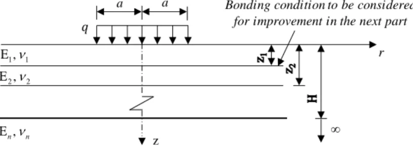
Figure 1 presents the multilayered pavement structure in cylindrical coordinates with r and z are the coordinates in the radial and vertical directions respectively. The load applied on the surface of the pavement is a uniform vertical pressure of magnitude and has a circular form of radius. The analytical results to the problem described above are the stress, strain and displacement fields in the pavement structure.
FIGURE 1. Multi-layered pavement structure
Equation 1 presents the axisymmetric layered elastic responses (stresses and
displacements) under a concentrated load.
1 0 m( ) * 1 m( ) * * 1 * 0 mJ (m ) 1 1 (1 2 m ) (1 2 m ) ( ) mJ (m ) 1 1 (2 m ) (2 m ) A ( ) 1 J (m ) H 1 1 (1 m ) (1 m ) (u ) E 1 ( ) J (m ) H 1 1 (2 4 m ) (2 4 m ) E i i i i zz i i i i rz i i i i i i i i e e w 1 m( ) m( ) B C D i i i i i e e (1) where * (zz i) and *(rz)i are the vertical and shear stresses, *
(u )iand *
(w )i are the horizontal and
vertical displacements of layer i; His the distance from the pavement surface to the upper boundary of the bottom layer r/ H and
z/ H; J0 and J1 are Bessel functions of the firstkind and order 0 and 1 respectively; Ai, Bi, Ci and Di are constants of integration to be determined from boundary and continuity conditions; m is a parameter.
The layers interface behaviour can be described according to Goodman's constitutive law [3] in which the interface shear stress can be expressed as follows:
Ks u
(2)
where is the relative horizontal displacement of the two layers at the interface;u Ksis the
horizontal shear reaction modulus at the interface. The continuity conditions for this general case are: 1 1 E , 2 2 E , E ,n n z
Bonding condition to be considered for improvement in the next part
r
a a
RUGC 2020 AJCE, vol. 38 (1) 87 * * 1 (zz i) (zz i) (3) * * * 1 (
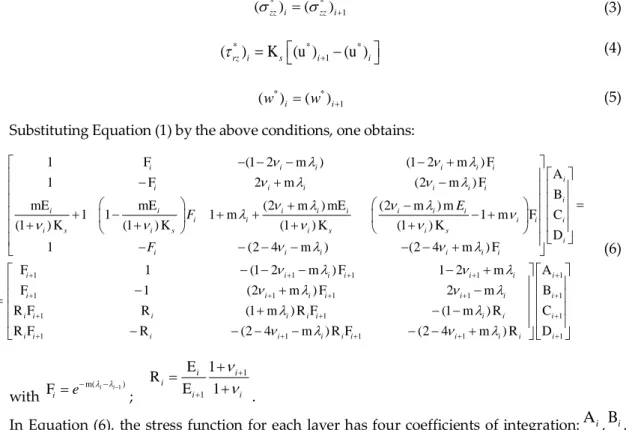
rz i) Ks(u )i (u )i (4) * * 1 (w )i (w )i (5)Substituting Equation (1) by the above conditions, one obtains:
1 F (1 2 m ) (1 2 m ) F A 1 F 2 m (2 m ) F B mE mE (2 m ) mE (2 m ) m 1 1 1 m 1 m F C (1 ) K (1 ) K (1 ) K (1 ) K D 1 (2 4 m ) (2 4 m ) F i i i i i i i i i i i i i i i i i i i i i i i i i i i i s i s i s i s i i i i i i i E F F 1 1 1 1 1 1 1 1 1 1 1 1 1 1 1 1 1 1 F 1 (1 2 m ) F 1 2 m A F 1 (2 m ) F 2 m B R F R (1 m ) R F (1 m ) R C R F R (2 4 m ) R F (2 4 m ) R D i i i i i i i i i i i i i i i i i i i i i i i i i i i i i i i i i i (6) with 1 m( ) F ii i e ; 1 1 E 1 R E 1 i i i i i .
In Equation (6), the stress function for each layer has four coefficients of integration:Ai,Bi, CiandDi. All responses can be calculated by these coefficients and integrations.
II. Sensitivity Analysis
Sensitivity analysis using the developed numerical program is presented in this paragraph. The variation of some most important pavement responses under the loading of a FWD in function of the interface bonding condition were evaluated. The main characteristics of the pavement structure used for this analysis are presented in Table 1.
TABLE 1. Pavement structure characteristics
Layer E (MPa) Poisson’s ratio Nominal 1 thickness (cm) Actual 2 thickness S-I (cm) Actual 2 thickness S-II (cm) Asphalt surface 9000 0.35 6.5 6.6 6.3 Interface - - - - - Asphalt base 9000 0.35 4.5 4.6 3.9 Subgrade 184 0.35 290 290 290 Concrete raft 55000 0.25 - - -
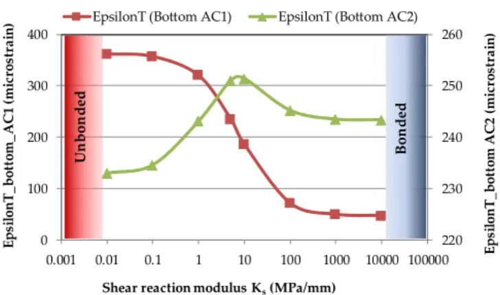
In an asphalt pavement, the horizontal strain at the bottom of the asphalt layer is among the most important parameters because its magnitude will affect directly the pavement performance. Generally the higher this magnitude is, the lower the pavement performance is. Figure 2 presents the horizontal strain at the bottom of each of the two asphalt layers of the investigated pavement structure in function of the bonding condition at the interface between the asphalt layers. As can be seen from Figure 2, when the bond modulus Ks decreases from infinite to nil, the horizontal
RUGC 2020 AJCE, vol. 38 (1)
88 strain at the bottom of the asphalt surface layer (EpsilonT_bottom_AC1) increases from 47 to 360 microstrains. Based on these evaluations, it is possible to classify the interface bonding condition as follow:
Ks ≤ 0.1 MPa/mm: Poor bond to unbonded
0.1 MPa/mm < Ks < 100 MPa/mm: Partially bonded
Ks 100 MPa/mm: Good bond to fully bonded.
FIGURE 2. Impact of the interface bonding conditions between the asphalt layers on the horizontal strains at the bottom of the asphalt layers.
Moreover, the pavement responses are more sensible for K between 0.1 and 100 MPa/mm than when K 100 MPa/mm or K ≤ 0.1 MPa/mm. Among the two horizontal strains, the one at the bottom of the base layer is less sensible than the other one of the surface layer.
CONCLUSIONS
The work presented in this paper focused on a better evaluation of structural behaviour of asphalt pavement. The analytical solution based on the layered theory was improved by introducing a shear reaction modulus (Ks) to take into account the interface bonding condition
between the asphalt layers. The numerical sensitivity analysis showed clearly the influence of interface bonding condition on pavement responses under the loading of a FWD. It allows classifying the interface bonding condition depending on the shear reaction modulus: poor bond to unbonded for Ks ≤ 0.1 MPa/mm; partially bonded for 0.1 MPa/mm < Ks < 100 MPa/mm; good
bond to fully bonded for Ks 100 MPa/mm.
REFERENCES
Burmister, D. M. The theory of stress and displacements in layered systems and applications to the design of airport runways. Highw. Res. Board, Proc. Annu. Meet 1943, 23, pp. 126−144.
Burmister, D. M. The general theory of stress and displacements in layered soil systems. I.J. Appl.
Phys.1945, 16(2), 89−94. [DOI: 10.1063/1.1707562]
Burmister, D. M. The general theory of stress and displacements in layered soil systems. II. J. Appl. Phys.
1945, 16(3), 126−127. [DOI: 10.1063/1.1707558]
Burmister, D. M. The general theory of stress and displacements in layered soil systems. III. J. Appl.
Phys. 1945, 16 (5), 296−302. [DOI: 10.1063/1.1707590] 220 230 240 250 260 0 100 200 300 400 0.001 0.01 0.1 1 10 100 1000 10000 100000 E p si lo n T _ b o tt o m A C 2 ( m ic ro st ra in ) E p si lo n T _ b o tt o m _ A C 1 ( m ic ro st ra in )
Shear reaction modulus Ks(MPa/mm)
EpsilonT (Bottom AC1) EpsilonT (Bottom AC2)
B on ded Un bon ded