First International Conference on Bio-based Building Materials
June 22nd - 24th 2015 Clermont-Ferrand, France
COMPRESSIVE AND SHEARING BEHAVIOR OF LIME AND HEMP CONCRETE
A. Youssef*, T. Lecompte, V. Picandet, N. Challamel
Université de Bretagne Sud, EA4250, LIMATB F, 56100 Lorient, France * Corresponding author; alice.youssef@univ-ubs.fr
Abstract
In the literature, most of blocks of Lime Hemp Concrete (LHC, hemp shiv and mineral binder mix) that have been studied show a brittle behavior and a very low mechanical strength. The formulations are generally rich in binder and slightly compacted. Up to now, this material is then not considered as a load bearing material and is mainly used as filler insulation, combined with structure components made of wood, concrete or masonry. Some other formulations have been tested, with higher contents of aggregates thanks to a compaction process, in order to improve both the rigidity and the strength of the hardened mixtures. The higher amount of shiv, lighter and more porous than lime, avoids significant increase in thermal conductivity. The present work is an experimental study of the compressive and shearing behavior of hemp concrete, in order to study the load-bearing capacity and bracing of this bio based material, while maintaining good qualities of thermal insulation. For this study, a special device has been developed. The samples tested with this device are cubic specimens of hemp concrete with 7 cm length. Two compacted formulations were tested, as well as samples obtained from LHC trade-blocks. Two series of tests are performed. The first one is a uniaxial compression test in each direction for characterizing the mechanical anisotropy of the material. This anisotropy is induced by the compacting process. The second one permits to characterize the shearing behavior of the different mix-designs. This is an original device, specifically designed for this kind of material, which allows shearing under controlled normal stress. The first results show a high ductility of this material in shear, which confirms the results of the literature on wall structures. These preliminary results are very promising especially for seismic applications.
Keywords:
Lime and hemp composite, mix design, compression moulding, rigid die, oedometric compression, compressive strength, shearing strength
1 INTRODUCTION
LHC (lime and hemp composite) are nowadays the most developed bio-aggregate-based building material in Europe. This material associates a mineral binder, usually a combination of hydraulic and non-hydraulic lime, with a plant-based aggregate, mostly consisting in shiv, without or with little residual fibers. Shiv is produced from the woody core of hemp stem, grounded and sieved into 5 to 40mm-in-length particles [Picandet 13]. Due to the environmental advantages of non-hydraulic lime and of hemp growing, LHC presents, during its life cycle, a weaker ecological impact [Arnaud 00, Boutin 06] compared to traditional building materials. However, LHC currently has a very weak compressive strength, less than 2 MPa [Cérézo 05, Bütschi 04, Eires 06, Elfordy 08, Bruijn 09, Arnaud 11, Kioy 05]. This low compressive behavior indicates that the material in its present form cannot be used as a load-bearing material. More rigidity and higher compressive strength are needed.
LHC walls can be made on site, the material poured in a framework and tamped manually, or sprayed using a projection process. These processes do neither achieve a high compactness or any precise control of conditions of maturation of the material. As a consequence, its resistance is very low. For example, French professional LHC building rules [CenC 12] give a compressive strength of 0.3 MPa for tamped LHC walls and floors. LHC can also be used to make bricks, or hollow blocks. The main asset of this method is to permit a better control of packing and arrangement of particles. It provides less dispersion of mechanical strength and thermal properties. This is the process developed in the present work. Furthermore, a controlled compaction of the fresh mixture during moulding is applied to improve the material properties, as in [Nguyen 09a, Nguyen 09b, Tronet 14]. These authors have shown that the compaction of fresh material can increase significantly the compressive strength of hemp concrete by reducing the volume of voids within the material. Such a process improves mechanical strength while using lower binder contents. It also magnifies the strain capacity before collapse.
Compacted LHC is pressed during casting. The aim is to have a structural or load-bearing function, while keeping good thermal insulation properties.
In the present work, two mix designs inspired by the work of Tronet et al. [Tronet 14a, Tronet 14b] are studied, and compared to the behavior of a current trade Hempcrete block (Chanvribloc®). Nozahic et al. [Nozahic 12] show that compacted blocks of bio-aggregate concretes have an anisotropic behaviour, from a mechanical point of view. The compaction induces an orientation of the shiv particles in layers, orthogonally to the compaction direction. In the other directions, the shiv is randomly orientated. It provides a transversely isotropic behavior. One aim of the present paper is to measure this degree of anisotropy in compression, and to evaluate the differences induced by the compaction state. On a mechanical point of view, the anisotropy is of interest if the LHC blocks are set in the same direction as the fabrication process. If it is not the case, the brittle behavior in the orthogonal direction could be problematic.
One limitation in the development of LHC is the cost, including the association with timber structural components. The wood sections are generally designed by considering that LHC blocks do not mechanically contribute to the building stability. Actually, LHC walls should be able to bear a part of the load, and provide a wind bracing resistance. This would reduce the wood cross sections, and potentially save structural material. Wind-brace tests have already been carried out on hempcrete installed by projection, by [Munoz 13]. They demonstrate that the presence of the hempcrete is not only able to substitute the bracing struts, but also to greatly improve both the rigidity and the strength in terms of bracing. Then, study of the shear behaviour of LHC blocks is of engineering interest. This is the second aim of this paper. A fitted shearing cell has been developed to measure the shearing strength on LHC cubes. This cubic geometry also allows to characterize the degree of anisotropy of this material in term of shearing.
The main objectives of this paper are: 1– Study the anisotropy induced in LHC blocks by the compaction level of the fabrication process 2– Measure the shearing behavior of LHC blocks.
2 MATERIAL AND PROTOCOL 2.1 Material
Trade hempcrete blocks
One of the tested materials comes from trade blocks provided by Chanvribloc®. Its real composition hasn’t been provided by the supplier, but it is essentially constituted of hemp shiv and hydraulic binder. Its density in the dry state is 340kg/m3. The blocks are vibrated in the fresh state during process. A low anisotropy could then appear on this kind of material, too.
Aggregates
In this study, the shiv has been totally separated from fibers using a mechanical grinding process. This biobased aggregate is characterized by a very low bulk density (about 110 kg/m3) because of its highly porous structure. The size of capillaries ranges from 10 to 50 µm inside aggregates. As a consequence, this aggregate exhibits a high water absorption capacity, up to 270% after a few minutes [Nguyen 09a; Chamoin 11]. Particle density of shiv is 280kg/m3 measured by
Pham [Pham 14]. Shiv particles are very porous, as their walls, mainly constituted of cellulose, have a density of about 1465kg/m3
Binder
A lime based binder called Tradical ® PF 70 (Lhoist group) was used. It consists of 75% hydrated lime Ca(OH)2, 15% hydraulic lime, and 10% pozzolana. Its specific density, given by the supplier, is 2450 kg/m3. 2.2 Mix designs and compression process in the
fresh state
Based on Tronet et al. [Tronet 14a, Tronet 14b], two LHC mixes, M1 and M4, were designed (Tab.1). M1 contains more binder but is less compacted than M4. In the compaction direction, Tronet et al. have shown that M4 is stronger than M1, due to its higher compactness in the hardened state.
The capillary and deformable character of shiv make the mixing more difficult than for traditional concrete or mortar. The mixing phase consists in two steps: 1– mixing of shiv and water during 4 minutes at 140 rpm in a planetary Hobart mixer; 2– adding lime and mixing during 4 minutes at 140 rpm. During the first step, the water is totally absorbed by the shiv. This means that the second step is similar to the mixing of dry particles. Water is released by aggregates as they are pressed in the compression cell. The amount of water needs to be calculated as a function of binder content, considering that most of water becomes available for lime wetting and hydration at the end of compaction.
Tab 1. Studied mixtures
M1 M4 Shiv (S) [kg/m3 of LHC] 215 500 Binder (B) [kg/m3 of LHC] 387 270 Water (W) [kg/m3 of LHC] 213 148 W/B 0.55 B/S 1.8 0.54 Green density [kg/m3] 816 920 Green compactness [-] 0.52 0.6 Compactness
In the hardened state [-] 0.37 0.55
W/B is the Water to Binder mass ratio, equal to 0.55 for each LHC mixture. B/S is the Binder to Shiv mass ratio. The compression device is composed of a steel 100mm-inner-diameter cylinder, a fixed lower punch, and a moving upper punch. The piston rod of the upper punch is screwed under a 250kN press, equipped with force and displacement transducers. The thickness of the cylinder wall is 10mm, ensuring a negligible strain up to a radial pressure of 10MPa. This compression device is more precisely described in [Tronet 14a]. The initial (bulk) apparent volume of the mixture poured into the cylinder is three to four times the final compacted apparent volume [Tronet 14a]. The target value for the final height was 200mm for every specimen. This is of the same order as trade compacted blocks (200 to 300 mm in height). Every test is controlled in displacement, with the same upper punch speed of 1mm/s. At the end of compression step, the specimen reaches a given compactness, called “green compactness” in Tab. 1. Compactness is effectively the most significant parameter to characterise the compaction state, due to the
Comp Comp
difference of specific gravity between water, shiv and lime. In this study, considered specific gravities of constituents are 1465 kg/m3 for the shiv walls and 2450 kg/m3 for the binder.
In the fresh state, compactness corresponds to the sum of solid volume fraction and liquid volume fraction, i.e. the volume of liquid and solid divided by the total volume of the sample. The liquid phase is included because it is assumed to be physically linked to lime and shiv at the end of compression step. This assumption is valid as soon as the water content is low, ensuring that no free and draining water exits from the sample. And effectively during compression, no loss of mass was recorded. At the end of compression process, each specimen is maintained to constant height of 200 mm, during 72 hours. This step is needed to ensure a minimum hydration of lime, avoiding capping and elastic release of the specimen when pushing out of the die. LHC blocks are then placed in a room controlled in temperature (20±1°C) and humidity (70±5%), until their mechanical characterisation. M4 blocks must also be clamped during maturation to avoid visco-elastic release. During ageing of LHC specimens, some liquid water is consumed by lime hydration and a large amount is evaporated. Then the compactness of samples decreases, as seen in Tab. 1. And this compactness decreases much more when paste contents are high. To have more details on the compaction process, see [Tronet14a]
2.3 Manufacturing of the cubic samples
Two cubic specimens with edges of 7cm are machined from each hardened LHC cylinders, one from the upper part and one from the lower part, as indicated in figure 1. In order to achieve this goal, a specific device has been developed to fit a band saw, ensuring a proper flatness and parallelism of the cube’s sides.
Fig. 1: L20cm x φ 10cm Cylinder block in the hardened state, and location of the cubic sample machined in
this cylinder
Five cubic specimens are fabricated for each test (shearing or uni-axial compression), each formulation (M1, M4 or Chanvribloc®), and each solicitation direction (parallel or orthogonal to compaction direction). Each specimen was weighted to measure its density.
Compressive behavior is measured in simple compression, under a 500kN press fitted with axial
force and displacement transducers. The
compressions are controlled in displacement with a displacement rate of 1mm/s to ensure quasi-static conditions. Four LVDT transducers are also positioned to measure the transversal strain during compression (Fig. 2). In the present work, the compressions are monotonic. Two directions of solicitation are studied: in parallel with the compaction direction (CP, Fig.3b), and orthogonally (CO, Fig. 3c).
2.4 Characterization of the compressive behavior
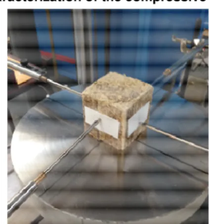
Fig. 2: Cubic sample before simple compression test.
a) c)
Fig. 3: (a) Cubic samples in the compacted cylinder, showing the orientation of the shiv ; (b)simple compression parallel with the compaction process ; (c)
simple compression orthogonal with the compaction process.
Fig. 4: Typical compression curve for strength and characterization of hardened compacted LHC cylinders Generally, hempcretes with high binder content or with high porosity are brittle, with a compressive strength corresponding to the maximum load reached during the test. Studies on compacted cylinders [Tronet 14b, Nguyen 9a, Nguyen 9b] show a different compressive behavior, closer to those of a rigid foam, as shown in Figure 4. This mixes are more ductile, with a large
plastic hardening zone. A curve with a similar shape was observed by Kioy on 10 cm LHC cubes [Kioy 05]. By comparing the behavior of a 10 cm-in-edge cube with a 10cm-in–diameter x 20cm–in-length cylinder, the behavior of the cube was found to be ductile with a plastic-hardening phase while those of the cylinder was more brittle. Nozahic et al. [Nozahic 12] show a ductile behavior in the compaction direction, and a brittle and more rigid behavior orthogonally to the compaction direction with parallelepipeds of bio-based materials with pumice-lime binder.
2.5 Characterization of the shearing behavior
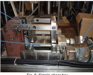
A dedicated shearing device was designed for this work. It is presented in figure 5. It consists in a simple shear box with the inner volume in the initial position corresponding to the studied sample (cubes of 7 cm or 10cm). The simple shear box has several advantages. The principal stresses rotate during the test, as they do in a wall during bracing solicitation. The use of relatively small specimens should permit every type of wall (thin or thick, compacted, dammed or projected…) to be sampled. One main theoretical disadvantage of this simple shear box is that the principal stresses cannot be derived from the data, so results cannot be compared easily with triaxial results or direct shearing results. The other main disadvantage is that stress and deformation are not uniform within the specimen. In particular, the part of the sample in the acute angles of the parallelogram formed during deformation tends to compact more than the average. According to [Airey 87] the measured stress at the boundary may underestimate the stress on the central third of the specimen by up to 10%. A further practical problem is that the forces applied to the shear box are not aligned, so they form a parasitic torque which tends to tilt the box during tests.
Fig. 5: Simple shear box
Nevertheless, the simple shear box is particularly useful for investigating behavior before failure occurs. Equipment of this type has been used for measuring the shear effects on gas transport in soil [O’sullivan 99]. One of our objectives was to design a device that was relatively simple.
Vertical load was applied to the specimen by placing the apparatus under a 250kN-press, while horizontal displacement of the lower plate of the box was produced by an electric screw jack. The upper axis (Fig. 5) doesn’t move horizontally, but is free to move vertically. Shear load, vertical load and both vertical and horizontal displacements are measured by transducers. Shear strain can be estimated as the horizontal displacement of the lower plate divided by
the height of the specimen. The maximum shear strain achievable with this apparatus was about 0.5. This box was intended to simulate deformation under bracing, with a low shear rate (about 0.015 s-1).
3 RESULTS
3.1 Density of the cubic samples in the hardened state
As seen in table 2, the density of every cubic specimen was measured. Values given in this table are mean value of at least five specimens. Due to friction during the molding and compression processes, an heterogeneity appears between the upper part and the lower part of the compacted LHC cylinder, with the same size order for M1 and M4. This phenomenon has been explained by [Tronet 14a]: during the compaction process, the wall of the cylinder compression cell bears a part of the compressive load. Then the pressure undergone by the mixture is lower in the bottom that in the top of the cylinder. It results in a lower compaction state in the bottom part, characterized by a lower density in the fresh state as in the hardened state.
Tab.2: Mean densities of the different mix-designs
Density [kg/m3] Top/Bottom Ratio M1 Top 660 1.15 Bottom 574 M4 Top 895 1.17 Bottom 765 Chanvribloc® 340 - 3.2 Compressive behaviour
Figure 6 show typical curves when the compression is applied orthogonally to the processing direction (compaction in the case of M1 and M4, vibration in the case of Chanvribloc®. Every mix has a plastic behaviour, showing a maximum stress. During the experiments, the M1 and M4 specimens break in “accordion”. This observation indicates that shiv layers, initially parallel to the principal stress, collapse by buckling. In these curves, the compression stress is quite easy to characterize: it corresponds to the peak of the stress-strain curve. Average compressive strengths, computed from the results of complete experimental program, are given in Tab 3. Figure 7 provides typical curve when simple compression is done in the same direction as fabrication compaction. In this case, shiv layers are perpendicular to the principal stress. The behaviour is very ductile, with a quasi-elastic part, and a plastic-hardening part. It is difficult to extract a readable compressive strength directly from these curves. Tronet et al. [Tronet 14b, Lecompte 15] suggest a meaningful stress parameter to compare the curves and characterise the strength of each sample. This parameter is the yield stress, computed as explained on figure 8. With this method, the different average yield stresses σy are given in Tab 3.
Firstly, it must be noted that the dispersion is very high in the case of compressions orthogonal to the fabrication direction (CO). The results should be correlated to the defaults and tensile behavior between the shiv layers. Nevertheless, the trend of a correlation
between the compressive strength and the compaction state (or density) is observed. It means that for higher content ratio of shiv (M4), the transverse compressive behavior remains better, even if there is less binder. This higher compressive strength is probably due to the porosity limitation and a more rigid behavior when the compactness decreases.
Fig. 6: Compressive behavior, orthogonally to the fabrication load (CO)- Typical curves for M1, M4 and
Chanvribloc®
Fig. 7: Compressive behavior, parallel with the fabrication load (CP)- Typical curves for M1, M4 and
Chanvribloc®.
Tab. 3 the yield stress in compressions parallel to the compaction load direction (CP) is always higher than the compressive strength orthogonal to the compaction load direction (CO). By comparing this stress with the results of Tronet et al. [Tronet 14b, Lecompte 15], it is observed that the resistance of a cylinder is close to the resistance of its weakest part, associated with the cube extracted from the bottom in the present study. It confirms that the friction along the compaction cell induces a significant heterogeneity of mechanical behavior within a same block. Such compacting process has to be technically improved to minimize this issue and ensure a better homogeneity of the precast elements.
The very unsteady and variable behavior of the samples in transverse direction, added to their low compressive strength, make them very difficult to be laid transversally as load-bearing material, even in a self-supporting wall.
The complementary tests made on cube of Chanvribloc® of different size (Edge length of 7 cm, 10 cm and 15 cm) have show that there is no size effect in this range of length. The curves have the same shape. It can be conclude that the size has a negligible effect compared to the aspect ratio of the specimens: comparison of the experimental work of [Tronet 14b] with the present study shows that the
values of the yield strength obtained on cubes (aspect ratio equals to 1) and on cylinders (aspect ratio equals to 2) are similar, but the plastic hardening is significantly magnified with the cubes.
Fig. 8: Determination of the yield stress σy, when
simple compression tests are in the compaction load direction (CP)
Tab.3: Compressive behavior of the different mix-designs in the two directions (CP) and (CO)
Compressiv e strength σσσσc [MPa] (CO) Yield stress σy [MPa] (CP) Yield stress σy obtained on cylinders by [Tronet 14b] [MPa] (CP) M1 Top 0.72±0.36 1.9±0.3 1.4 Bottom 0.31±0.16 1.18±0.14 M4 Top 1.62±0.51 6.87±0.58 4.7 Bottom 1.3±0.07 4.3±0.85 Chanvribloc® 0.13±0.06 0.27±0.12 - 3.3 Shearing behaviour
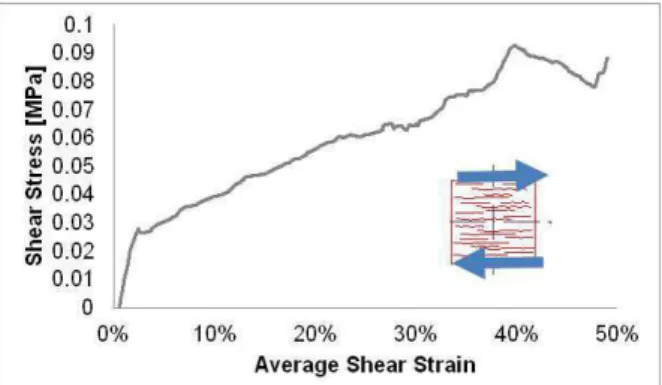
The figures 9 to 11 show the first results obtained thanks to the simple shear box. It can be observed that no sudden collapse occurs during these experiments. For mixes M1 and Chanvribloc, a change in the slope seems to appear when the strain reaches 2%. It could correspond to a transition between an elastic phase and a plastic phase of shearing, as already observed in case of parallel compression.
The absence of brittle phase in the shear response, for each tested material, is certainly a good feature for structural applications: it could provide energy dissipation by deformation, in case of earthquake for example. Contrarily to usual construction materials, LHC blocks, even for slightly compacted materials, can play a role as earthquake-proof material.
As observed in figure 11, the shearing rigidity will be correlated with the confinement load (vertical load applied by the press). This result is well known in soils mechanics, and permits to draw yielding lines to obtain the cohesion and the internal angle of a given soil. In the present case, the absence of a perfect plasticity (or flowing) phase prevents this kind of study. Nevertheless, one can assume that the shearing occurs by sliding and friction of the shiv layers. To go further in this work, complementary experiments have to be done: the measurement of the deformation field with a camera and a picture-processing software based on image correlations should give some indications about the shear behavior and localization
into the sample. Shearing in other directions (transversal to the shiv layers, and into the layers planes) should also be done.
Fig. 9: Shear test applied orthogonally to the fabrication direction (SO)- Chanvribloc with a vertical
load of 0.2MPa
Fig. 10: Shear test applied orthogonally to the fabrication direction (SO)- M1 with a vertical load of
1MPa
Fig. 11: Shear test applied orthogonally to the fabrication direction (SO)- M4 Top with a vertical load
of 1MPa (dotted line) and 2MPa(solid line)
4 CONCLUSION
Cubic samples of LHC were tested both in compression and in shearing. For this purpose, an original shearing set-up was designed.
The compressive experiments have shown that this material is anisotropic, even when it is industrially moulded by vibrations. The transverse behaviour is very brittle, with a highly variable and unsteady behaviour.
In the quasi-elastic area, the behaviour of cubes (aspect ratio equals to 1) is similar to those of cylinders (aspect ratio equals to 2). In the plastic-hardening phase, decreasing the aspect ratio means increasing the rigidity.
Concerning the shear box set-up, first exploratory experiments were done. They show that the shearing rigidity is correlated with the normal stress, as in soils mechanics, and that the shearing behaviour of LHC blocks is very ductile. These experimental results confirm the results already obtained in previous experimental study [Munoz 13], An interesting behaviour of LHC walls in term of potential bracing, needing more investigations, is pointed out.
5 REFERENCES
[Airey 87], Airey DW, Wood D.M., An evaluation of direct simple shear tests on clay. Géotechnique 1987;37:25-35.
[Arnaud 00] Arnaud L, Mechanical and thermal properties of hemp mortars and wools: experimental and theoretical approaches, Bioresources Hemp 2000 [Arnaud 11] Arnaud L, Gourlay E. Experimental study of parameters influencing mechanical properties of hemp concrete, Construction and building materials 2011;28:50-56.
[Boutin 06] Boutin MP, Flamin C, Quinton S, Gosse G. Etude des caractéristiques environnementales du chanvre par l’analyse de son cycle de vie. Ministère de l’agriculture et de la pêche, France, 2006.
[Bruijn 09] Bruijn PB, Jeppsson KH, Sandin K, Nilsson C. Mechanical properties of lime – hemp concrete containing shives and fibres. Biosystems Eng 2009; 103: 474-479.
[Bütschi 04] Bütschi PY. Utilisation du chanvre pour la préfabrication d’éléments de construction. PhD Thesis, Moncton University, Moncton, Canada, 2004.
[CenC 12] Construire en chanvre, règles professionnelles d’exécution de construction, SEBTP 2012, ISBN : 978-2-35917-046- 7
[Cérézo 05] Cérézo V. Propriétés mécaniques, thermiques et acoustiques d’un matériau à base de particules végétales : approche expérimental et modélisation théorique. PhD Thesis, INSA Lyon, France, 2005.
[Chamoin 11] Chamoin J, Collet F, Pretot S, Lanos C. Réduction du pouvoir absorbant de chènevottes par traitement imperméabilisant, Matériaux & Techniques 2011, EDP Sciences, 99(6), 633–641.
[Eires 06] Eires R, Nunes P, Fangueiro R, Jalali S, Cameos A. New eco-friendly hybrid composite materials for Civil construction. European Conference on Composite Materials. Biarritz, May, 2006.
[Elfordy 08] Elfordy S, Lucas F, Tancret F, Scudeller Y, Goudet L. Mechanical and thermal properties of lime and hemp concrete (« hempcrete ») manufactured by a projection process. Construction and Building Materials 2008;22 (10):2116-2123.
[Kioy 05] Kioy S. Lime-hemp composites: compressive strength and résistance to fungal attacks. MEng dissertation, University of Bath, 2005, recalled in Appendix 1: Resistance to compression and stress-strain properties, In: Bevan Rand Woolley T, editors. Hemp Lime Construction, A guide to building with hemp lime composites, IHS BRE press, 2013. p. 101-104
[Lecompte 15] Lecompte T, Picandet V, Tronet P, Baley C, Study of lime and hemp concrete (LHC) – mix design, casting process and mechanical behaviors, 2015, ICBBM, Clermont Ferrand, France.
[Munoz 13] Munoz P, Pipet D, Plant-based Concretes in structures: Structural aspect-addition of a wooden support to absorb the strain, In: Amziane S, Arnaud L, editors. Bio-aggregate-based Building Materials. London/Hoboken: ISTE/Wiley, 2013:267-287.
[Nguyen 09a] Nguyen TT, Picandet V, Carré P, Lecompte T, Amziane S, Baley C. Effect of compaction on mechanical and thermal properties of hemp concrete, EJECE 2009;13:1039-1050.
[Nguyen 09b] Nguyen TT, Picandet V, Amziane S, Baley C. Influence of compactness and hemp hurd characteristics on the mechanical properties of lime and hemp concrete, EJECE 2009;13:1039-1050. [Nguyen 10] Nguyen TT. Contribution à l’étude de la formulation et du procédé de fabrication d’éléments de construction en béton de chanvre, PhD thesis, Université de Bretagne-Sud, 2010.
[Nozahic 12] Nozahic V, Amziane S, Torrent G, Saïdi K, De Baynast H. Design of green concrete made of plant-derived aggregates and a pumice-lime binder Cement and concrete composites 2012, 34, 231-241.
[O’Sullivan 99] O’Sullivan MF, Robertson EAG, Henshall JK, Shear effects on gas transport in soil, Soils and Tillage Research 1999; 50:73-83.
[Pham 14] Pham T.H., Modélisation multi-échelles des propriétés thermiques et élastiques de composites chaux-chanvre, PhD thesis, Université de Bretagne-Sud, 2014.
[Picandet 13] Picandet V. Characterization of Plant-Based Aggregates. In: Amziane S, Arnaud L, editors.
Bio-aggregate-based Building Materials.
London/Hoboken: ISTE/Wiley, 2013:27-73.
[Tronet 14a] Tronet P, Lecompte T, Picandet V, Baley C. Study of lime and Hemp composite precasting by compaction of fresh mix – A Fitted die to measure friction and stress state, Powder Tech., 2014, 258:285-296.
[Tronet 14b] Tronet Pierre, contribution à l’étude des matériaux chaux-chanvre: influence du compactage sur les propriétés, PhD thesis, Université de Bretagne-Sud, 2010.