HAL Id: hal-00826565
https://hal.archives-ouvertes.fr/hal-00826565
Submitted on 27 May 2013
HAL is a multi-disciplinary open access
archive for the deposit and dissemination of
sci-entific research documents, whether they are
pub-lished or not. The documents may come from
teaching and research institutions in France or
abroad, or from public or private research centers.
L’archive ouverte pluridisciplinaire HAL, est
destinée au dépôt et à la diffusion de documents
scientifiques de niveau recherche, publiés ou non,
émanant des établissements d’enseignement et de
recherche français ou étrangers, des laboratoires
publics ou privés.
One-step synthesis and chemical characterization of Pt
C nanowire composites by plasma sputtering
Pascal Brault, Amaël Caillard, Steve Baranton, Mathieu Mougenot, Stéphane
Cuynet, Christophe Coutanceau
To cite this version:
Pascal Brault, Amaël Caillard, Steve Baranton, Mathieu Mougenot, Stéphane Cuynet, et al..
One-step synthesis and chemical characterization of Pt C nanowire composites by plasma sputtering.
ChemSusChem, ChemPubSoc Europe/Wiley, 2013, 6, pp.1168-1171. �10.1002/cssc.201300236�.
�hal-00826565�
One-step synthesis and chemical characterization of
Pt-C nanowire composites by plasma sputtering
Pascal Brault,
[a]Amaël Caillard,
[a]Stève Baranton,
[b]Matthieu Mougenot,
[a]Stéphane Cuynet,
[a]and
Christophe Coutanceau,
*[b]Small size of nanoparticles (NPs) is proposed as responsible of their specific properties.[1-3] Nanomaterials have thus found numerous applications in chemistry, electronics, optics,
information storage, medical, biotechnology.[4] Numerous
processes of heterogeneous catalysis (vehicle exhaust and industrial effluent treatments, petrochemistry, sensors, energy storage and conversion...) used costly and strategic metals from the platinum group.[5] Here, a high surface-to-volume ratio
leading to large fraction of accessible atoms is required for increasing the activity of the catalyst.[6-8] There is thus a real interest to obtain the highest catalytic surface area from a low metal weight, as for fuel cells [9] or sensors. On the other hand, carbon nanofibers or carbon nanotubes have been proposed as catalytic support[10-12] in place of carbon powders because of
their high electrical conductivity, unique surface structure, large
surface area and chemical inertia.[13] Moreover, metal NPs
deposited on carbon nanotubes or carbon nanofibers display higher electrocatalytic activity and stability.[14,15] Therefore, numerous multistep syntheses of carbon nanowire arrays were
developed, such as template methods[16] and catalytic
growths[17].
Here we report a plasma-assisted one-step synthesis of Pt/C nanowires (Pt-CNW). Such synthesis method is convenient for controlling the metal spreading on a porous support, its localization in depth and the metal NPs size distribution.[18,19] It is an environmental-friendly process (time, energy and atom savings, no harmful chemicals, organic solvent or precursor). The co-sputtering of platinum and carbon atoms on an E-Tek® carbon porous layer (CPL) is achieved in a magnetron sputtering reactor. Two rectangular targets, one
of pure carbon and one of Pt1C99 (atomic ratio), are
simultaneously DC biased at fixed power leading to a thin film growth rate of ca. 4 nm min-1. Electrodes loaded at 0.010 mg
cm-2 Pt (Pt-CNW/CPL) with a Pt ratio of ca. 30 at% in the
deposited film are produced. The Pt loading and localization profile inside the CPL is determined using Rutherford Backscattering Spectroscopy: 90% of Pt atoms are localized in the first 200 nm depth of the material.
The general morphology of Pt-CNW/CPL (Figure 1a) resembles that of a cauliflower with platinum clusters forming dense sponge-like film on the surface of carbon grains. The
TEM image in Figure 1b shows that a platinum film (darker zones) is deposited on the top of the CPL surface (light grey zones). Columnar structures emerge in the radial direction of the platinum film with respect to the CPL support. Higher magnification in Figure 1c reveals a Pt NPs arrangement surrounding carbon nanowires over their whole length. The carbon column enlargement from the bottom (ca. 5 nm) to the top (ca. 10 nm) is explained in terms of a shadowing effect in magnetron sputtering process.[20] Increasing the magnification allows visualizing the platinum clusters and estimating their size to ca. 1 nm (Figure 1d).
Figure 1. (a) SEM picture of a 0.010 mg cm-2
Pt on a commercial CPL (courtesy of D. Cot, IEM); (b-d) TEM images of 0.010 mgPt cm-2 Pt-CNW on a commercial CPL at different magnifications.
ToF SIMS was used to analyze the chemical structure of the material. Due to the complexity of the sample, a lot of mass peaks are recorded and only semi-quantitative analysis can be
performed. CHxPt and CHxOPt are the main molecular ions
detected, indicating that strong chemical bonds exist between Pt atoms and carbon or oxygen atoms, which is a good point for activity and durability issues.[21] ToF SIMS and XPS (Figure 2) measurements show that Pt is mainly under oxidized states (PtOx, PtOxHy). Platinum is only found under +II oxidation state
by XPS. Plasma synthesis is performed under argon
atmosphere, free of O2 and water molecules. Oxygenated
species could come from the targets and be sputtered with Pt and C atoms. The edges of graphene planes are likely ended
by hydrogen atoms or oxygenated functions.[22] Because ToF
SIMS and XPS measurements were not conducted in situ, the oxidation of the Pt and C atoms could also occur as soon as the Pt-CNW/CPL is put in contact with air, forming surface oxides.[23] XPS analysis of 2.5-3.0 nm Pt NPs synthesized by
[a] Dr. P. Brault, Dr A. Caillard, Dr M. Mougenot, Dr S. Cuynet Groupe de Recherches sur l’Energétique des Ionisés (GREMI),
Université d’Orléans, UMR CNRS 7344 14, rue d’Issoudun, 45067, Orléans cedex 2, France
E-mail:pascal.brault@univ-orleans.fr
[b] Prof. C. Coutanceau, Dr. S. Baranton Institut de Chimie des Milieux et Matériaux de Poitiers, IC2MP, Université de Poitiers, UMR CNRS 7285 4, rue Michel Brunet, B27, 86022, Poitiers, France E-mail:christophe.coutanceau@univ-poitiers.fr
a
b
colloidal routes[24,25] showed that Pt atoms on particle surface were +II oxidation state, whereas core Pt atoms remained under metallic state.[26] For Pt particles co-deposited with carbon by plasma method, all Pt atoms are found to be oxidized, confirming that the Pt particle size is close to 1 nm. In the case of (hemi)spherical Pt particles,[19] the dispersion D (ratio of surface Ns to total Nt atom numbers) is inversely
proportional to the diameter of the particle d in nm[27]; 5 nm
diameter particle has 20% surface atoms (Nt ≈ 6 000 atoms),
and for 1 nm, one can consider all atoms as surface atoms. The XRD pattern showed no diffraction peak corresponding to Pt fcc structure, only a broad peak at ca. 25° characteristic of carbon, several peaks assigned to the presence of PTFE in the commercial CPL and a potato-like background, which translates the very low Pt loading and a very amorphous structure. This result is coherent with the very small particle size suggested by TEM and XPS measurements.
Figure 2. XPS spectra for Pt 4f orbital of 0.010 mgPt cm-2
Pt-CNW deposited on (a) a Si wafer and (b) a commercial CPL.
Integration of the hydrogen desorption current in the voltammograms (Figure 3) gives the electrochemical active surface area (EASA)[28,29]. Values ranging from 150 to 200 m2 gPt-1 were obtained for Pt-CNW/CPL against ca. 50 m2 g-1 for a
reference Pt (40wt.%)/C catalyst made by a colloidal method.[30] Assuming spherical particles of similar radius and
whole Pt particle surface utilization, a mean particle size d of ca. 1.3 – 1.8 nm is calculated.[26] Values are higher than that estimated from TEM. The contact between Pt NPs in agglomerates and between Pt NPs and carbon can avoid the accessibility to Pt sites. CxHyOz species formed on the Pt
surface can also be involved. The assumption of spherical particle could also not be valid. After numerical simulation the
equilibrium shape of small nanometric clusters could be the icosahedron,[31] which is the most compact shape close to the spherical one, but the equilibrium shape of a supported crystal is the Wulf polyhedron for a free crystal truncated at the interface (here a truncated cuboctahedron).
•
Figure 3. Cyclic voltammograms recorded on (a) 0.010 mgPt cm-2 Pt-CNW/CPL electrode and (b) classical Pt/C electrode with 117 µg cm-2of
Pt for powders with metal loading of40 wt.%.(scan rate = 50 mV s-1, N2 saturated, 0.05 mol dm-3 H2SO4, T = 20°C).
The oxygen reduction reaction (ORR) at the cathode of Proton Exchange Membrane fuel cells is very challenging and is activated by platinum-based catalysts for reaching
acceptable kinetics.[32-34] Pt-CNW/CPL materials were then
evaluated as cathode catalyst under the harsh fuel cell working conditions. The voltage/power density vs current density curve in figure 4 was obtained with two 0.010 mgPt cm-2 Pt-CNW/CPL
electrode pressed on a Nafion 212 membrane. At 80°C, a
maximum power density of 0.40 W cm-2 is achieved, i.e. 20 kW
gPt-1 (highest platinum utilization ever obtained). Fuel cells
performances obtained with the reference Pt(40 wt.%)/C catalyst were previously found higher, with a maximum power density of ca. 1.2 W cm-2, but with Pt loading of ca. 0.35 mg cm-2 in electrodes, leading to a Pt utilization rate of only 1.7 kW gPt-1.[30] 85 80 75 70 65
Binding energy / eV
1000 cpsa
b
85 80 75 70 65Binding energy / eV
1000 cps 0 0,2 0,4 0,6 0,8 1 1,20.0
0.2
0.4
0.6
0.8
1.0
1.2
-0.4
-0.2
0.0
0.2
0.4
I / m
A
E vs. RHE / V
Pt-H Pt + H++ e--0.4
-0.2
0.0
0.2
0.4
I / m
A
0.0
0.2
0.4
0.6
0.8
1.0
1.2
E vs. RHE / V
a
b
Figure 4. (a) E(j) and (b) P(j) curves obtained at 70°C with a MEA of Nafion
212 membrane sandwiched between symmetrical 0.010 mgPt cm-2 Pt-CNW/CPL electrodes (Flow rates: O2 = 350 sccm, H2 = 500 sccm; TO
2 = 40° C, TH
2 = 80° C, PO2 = 4bars, PH2 = 3 bars).
The controlled co-sputtering of platinum and carbon on a porous carbon layer led to a one step formation of carbon nanowires decorated by platinum NPs with diameters from 1 to 2 nm. Strong chemical bonds exist between platinum atoms and carbon or oxygen atoms, and platinum is observed mainly under oxidized states. Very high active surface area and catalytic activity towards ORR were obtained. The film structure, consisting in very small Pt particles decorating carbon columns with strong interactions, is responsible of the very high metal utilization rate, as exemplified by the electrochemical performances of the material as fuel cell electrodes.
Migration/aggregation of Pt crystallites, Otswald ripening, dissolution of metal and carbon support corrosion are the main degradation processes of Pt/C classical electrodes. The strong interaction between the carbon support and the platinum atoms
is according to Zhou et al.21 a good point for activity and
durability issues. According to the Gibbs-Thompson relation the thin film layer structure composed of agglomerated metallic nanoclusters is expected to cause an increase in their chemical potential, and to translate into lower Pt corrosion
kinetics.[35] The relatively dense thin film of Pt cluster
surrounding the carbon nanowires (at the nanoscale level) and the carbon CPL (at a higher scale) is expected to lower metal/carbon/oxygen contact, which could decrease the support corrosion rate. Moreover, the procedure for fuel cell tests imposed the condition that, before fuel cell experiments for several days, the cell had to be conditioned for 2 days at 80 °C with humidified hydrogen and oxygen fed to the anode and the cathode, respectively. Therefore, because the cell performance was maintained for several days, the nanocomposite structure could be considered to be stable on the FC experimental timescale.
Although the electrode fabrication process is relatively expensive (targets and high vacuum conditions) and fuel cell performances remain too low for automotive applications, where the electric kW cost has to be low (EU FP7 and US DoE targeted 50 € / kW for electric vehicle), such technology of
electrode fabrication is quite applicable for stationary and portable applications. Moreover, physical deposition methods under high vacuum conditions are routinely used in many sectors of industry, especially in metallurgy and microelectronics domains, where the cost reduction is primordial. At last, the very high Pt utilization makes this material convenient for sensor applications, where the environmental (temperature, pressure, corrosive medium) and electrochemical conditions are smoother.
Experimental Section
SEM and TEM measurements are carried out with a Hitachi S-4800 and a JEOL JEM 2010 (equipped with a LaB6 filament and with a resolution of 0.35 nm), respectively.
XPS measurements are performed with an Escalab MKII (VG scientific) set-up using the Magnesium monochromatic beam (1253.6 eV), at room temperature below 8 10-9 Torr pressure in the analysis chamber. Core level spectra are recorded with a 50 meV resolution. Binding energies are lined up with respect to the C 1s peak at 284.6 eV.
TOF SIMS measurements are carried out with an IONTOF SIMS IV apparatus on different zones (analyzed surface =
1600 μm2
)of a Pt-CNW/CPL to check the homogeneity of the
sample.
Electrochemical measurements are performed with a computer
controlled Voltalab PGZ 402 potentiostat, at 20°C in N2
-saturated (U quality from l’Air Liquide) 1.0 M NaOH (suprapur from Aldrich) electrolyte. A glassy carbon plate as counter electrode and a reversible hydrogen electrode as reference are used; all potentials are referred to the reversible hydrogen electrode (RHE).
For fuel cell measurements two 5 cm2 surface area 0.010 mgPt
cm-2 Pt-CNW/CPL electrodes are mechanically pressed on a
Nafion 212 membrane (Quintech, Germany) at 2 Nm torque in the cell hardware (Electrochem). Measurements are performed using a ECL150/MTS 150/HSA unit (Electrochem. Inc.).
Acknowledgements
“Agence Innovation MID” is acknowledged for granting a fellowship (MM). CNRS is acknowledged for granting the PIE “AMEPlas” and ANR is acknowledged for funding the Emergence project “AMADEUS”. GdR PACS-CNRS is acknowledged for constant support.
Keywords: Carbon • Composite • Nanostructure • Nanowires •
Plasma • Platinum
[1] G.A. Somorjai, Y.G. Borodko, Catal. Lett. 2001, 76, 1-5
[2] K. Kinoshita, in Modern aspects of electrochemistry, Vol. 14 (Eds: C. G. Vayenas, R. E. White, M .E. Gamboa-Aldeco), PLENUM, New York, 1982, pp. 557-637.
[3] K. P. McKenna, in Nanoscale materials in chemistry, (Eds: K. J. Klabunde, R. M. Richards), WILEY, Hoboken, N J, 2009, pp. 15-36. [4] A. Nel, T. Xia, L. Madler, N. Li, Science 2006, 311, 622-627. [5] C. Hageluken, Chimica Oggi/Chemistry today 2006, 24, 14-17.
0 100 200 300 400 0 0.2 0.4 0.6 0.8 1 1.2 1.4 j / Acm-2 P / m W c m -2 0 0.2 0.4 0.6 0.8 1 1.2 0 0.2 0.4 0.6 0.8 1 1.2 1.4 j / Acm-2 U cel l / V 0 100 200 300 400 500 a b
[6] R. Narayanan, M. A. El-Sayed, J. Am. Chem. Soc. 2004, 126, 7194-7195.
[7] A. S. K Hashmi, G. J. Hutchings, Angew. Chem., Int. Ed. 2006, 45, 1897-1899.
[8] Y. J. Xiong, B.Wiley, Y. N. Xia, Angew. Chem., Int. Ed. 2007, 46, 7157-7159.
[9] E. J. Yoo, T. Okata, T. Akita, M. Kohyama, J. Nakamura, I. Honma,
Nano Lett. 2009, 9, 2255-2259.
[10] B. C. H. Steele, A. Heinzel, Nature 2001, 414, 345-352. [11] E. Antolini, Appl. Catal. B: Environmental 2009, 88, 1-24.
[12] K. I. Tanaka, M. Shou, Y. Yuan, J. Phys. Chem. C 2010, 114, 16917-16923.
[13] P. Serp, E. Castillejos, ChemCatChem 2010, 2, 41-47.
[14] S. L.Candelaria, Y. Shao, W. Zhou, X. Li, J. Xiao, J.-G. Zhang, Y. Wang, J. Liu, J. Li, G. Cao, Nano Energy 2012, 1, 195-220.
[15] A. Caillard, C. Charles, P. Brault, R. Boswell, C. Coutanceau, Appl.
Phys. Lett., 2007, 90, 223119 - 1-223119-3.
[16] N. A. Melosh, A. Boukai, F. Diana, B. Gerardot, A. Badolato, P. M. Petroff, J. R. Heath, Science 2003, 300, 112-115.
[17] Z. F. Ren, Z. P. Huang, J. W. Xu, J. H. Wang, P. Bush, M. P. Siegal, P. N. Provencio, Science 1998, 282, 1105-1107.
[18] P. Brault, C. Josserand, J.-M. Bauchire, A. Caillard, C. Charles, R. W. Boswell, Phys. Rev. Lett. 2009, 102, 045901-1 - 045901-4.
[19] M. Cavarroc, A. Ennadjaoui, M. Mougenot, P. Brault, R. Escalier, Y. Tessier, J. Durand, S. Roualdès, T. Sauvage, C. Coutanceau,
Electrochem. Comm. 2009, 11, 859-861.
[20] M. Mougenot, P. Andreazza, C. Andreazza-Vignolle, R. Escalier, T. Sauvage, O. Lyon, P. Brault, J. Nanopart. Res. 2012, 14, 672. [21] Y. Zhou, K. Neyerlin, T. S. Olson, S. Pylypenko, J. Bult, H. N. Dihn, T.
Gennet, Z. Shao, R. O’Hayre, Energy Environ. Sci. 2010, 3, 1437-1446.
[22] K. Kinoshita, in Carbon: electrochemical and physicochemical
properties. J. WILEY AND SONS, New York, 1987, pp. 83-173.
[23] W. Vogel, J. Phys. Chem. C 2008, 112, 13475-13482.
[24] H. Bönneman,W. Brijoux, R. Brinkmann, E. Dinjus, T. Joussen, B. Korall, Angew. Chem. Int. Ed. 1991, 30, 1312-1314.
[25] M. Boutonnet, J. Kizling, P. Stenius, G. Maire, Colloids Surf. 1982, 5, 209-225.
[26] R. Sellin, J-M. Clacens, C. Coutanceau, Carbon 2010, 48, 2244-2254. [27] C. Henry, in Nanomaterials and nanochemistry, (Eds. C. Bréchignac,
P. Houdy, M. Lahmani), SPRINGER, Verlag, 2007, pp. 3-32. [28] C. Coutanceau, S. Baranton, T. W. Napporn, in The Delivery of
Nanoparticles, (Ed. A. Hashim), InTech Publisher, Rijeka, 2011, pp.
403-430.
[29] T. Biegler, D. A. J. Rand, R. Woods, J. Electroanal. Chem. 1971, 29, 269-277.
[30] A.J.-J. Kadjo, P. Brault, A. Caillard, C. Coutanceau, J.-P. Garnier, S. Martemianov, J. Power Sources 2007, 172, 613-622.
[31] C. Mottet, J. Goniakowski, F. Baletto, R. Ferrando, G. Tréglia, Phase
transitions 2004, 77, 101-113.
[32] T. R. Ralph, M. P. Hogarth, Platinum Metal Rev. 2002, 46, 3-14. [33] H. A. Gasteiger, S. S. Kocha, B. Sompalli, F. T. Wagner, Appl. Catal.
B: Environmental 2005, 56, 9-35.
[34] V. R .Stamenkovic, B. S. Mun, M. Arenz, K. J. J. Mayrhofer, C. A. Lucas, G. Wang, P. N. Ross, N. M. Markovic, Nature Mater. 2007, 6, 241–247.
One-step synthesis and chemical characterization of Pt-C nanowire composites by plasma sputtering
COMMUNICATION
A one-step synthesis of Pt-C nanowire composites using a plasma co-deposition method is reported. Electrodes with a Pt loading as low as 0.010 mg cm-2 are obtained. Pt particles with sizes from 1 to 2 nm are decorating with strong interactions columnar carbon nanostructures. The composite microstructure isresponsible of the very high metal utilization rate as exemplified from reactions involved in fuel cell electrodes (20 kW gPt-1).
Pascal Brault, Amaël Caillard, Stève Baranton, Matthieu Mougenot, Stéphane Cuynet, and Christophe Coutanceau,*
One-step synthesis and chemical characterization of Pt C nanowire composites by plasma sputtering
Supporting informations
One-step synthesis of Pt-C nanowire composite materials by
plasma sputtering
C. Coutanceau, P. Brault, A. Caillard, S. Baranton, M. Mougenot, S. Cuynet
Plasma co-sputtering method for synthesis
Pt-CNW are synthesised on a commercial CPL (Elat from E-Tek) in a plasma sputtering apparatus. Figure 1 shows the TEM image of the CPL.
50 nm
Figure 1: TEM image of the CPL used for Pt-C co-deposition by plasma sputtering.
Before deposition process, the 304L cylindrical stainless steel chamber is pumped to 5 10-6 mbar using a 500 L s-1 turbomolecular
pump (TV-551 NavigatorTM from Varian®). The CPL is introduced into the deposition chamber through a load lock unit and placed on a 20 x 20 cm² substrate holder. The argon pressure is adjusted to 75 µbar. Two high purity planar targets (one of pure carbon the other of Pt1C99 atomic ratio) are simultaneously DC biased at fixed power of 530 W (target current 0.78 A, target voltage 700 V). The
targets are placed at a distance of 10 mm from the substrate holder at an angle of 45° with respect to the substrate holder axis. The deposition rate of each material, the Pt loadings and the distributions into the commercial CPL were measured using Rutherford
Backscattering Spectroscopy (RBS)[1] in the laboratory CEMHTI (Orleans, France). A 2 MeV α particle beam (1 x 1mm²) produced in
a Van de Graaf accelerator impinges onto the Pt-CNW material. The α particles are backscattered after colliding with a carbon atom or a Pt atom and they are collected by a 25 mm² α detector (placed at 70 mm from the sample with a scattering angle of 165°). Their energy depends on the mass and on the in-depth position of the collision. The sticking coefficients of Pt and C atoms on Si were
found to be equal to the one on commercial CPL. The deposition time was adjusting to reach a Pt loading of 0.010 mg cm- 2 and a
ratio of 30 wt% of Pt in the deposited film. Figure 2 shows the RBS spectrum of the 0.01 mgPt cm-2 loaded CPL. On the right side of
the spectrum, the asymmetric peak corresponds to the Pt atoms. The area under this Pt peak is related to the number of Pt atoms inside the Pt-CNW material. The tail on the left side of the Pt peak indicates that the Pt atoms have diffused into the porous CPL. Pt distribution in the depth of the material can be deduced [2].
905 940 980 1015
Channels
Energy / keV
1720 1760 1800 1840 1880
R
e
tr
odif
fus
e
d
4He
pa
rt
ic
le
s
1700
1200
700
200
Figure 2: RBS spectrum of Pt from which the platinum density profile (inset) in the composite Pt-CNW/CPL material was determined; experimental data are
represented by the red curve, the blue curve is the simulated one to access the density profile.
ToF SIMS analysis
The ToF SIMS surface analysis technique consists in impinging the surface of a sample with a primary ion beam (in the present case
69Ga+) and to analyze the ejected secondary ions. By measuring the ratio masse/charge (m/z) of secondary ions and their time of
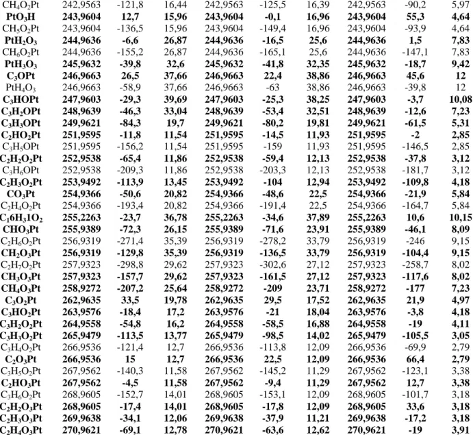
flight between the sample and the detector, the elemental composition and the chemical structure of the material upper layers can be determined. The depth resolution is 1-3 monolayers, the atomic resolution is lower than 5 x 10¹¹ at cm-2. Three different zones of the samples were measured in order to check the homogeneity of the material. The analysis chamber pressure is set at 5 10-9 Torr. The primary ions source of 69Ga+ is powered at potential of 15 kV leading to 0.67 pA pulsed ionic current (100 ns). The Molecular ions with mass from 1 to 400 containing C, O, H and Pt were searched in the spectra corresponding to positive and negative polarity of ions (Table 1). Several molecular ions could correspond to the same m/z value; however, the DtMass value may help to discriminate the molecular ions: the lower is its absolute value, the closer is the measured mass to the calculated one (the more probable molecular ions are in bold characters). Moreover, due to dependence of the ionic yield of secondary ions on the matrix, the ion intensity is not directly proportional to their concentration; however, while the same matrix is involved for all secondary ions, semi-quantitative analysis could be performed, and the main molecular fragments, in terms of amount, could be pointed out.
Molecular peak from ToF SIMS
Positive
molecular
ions
Sample 1
Sample 2
Sample 3
Ct Mass
Dt
Mass
CI
Ct Mass
Dt
Mass
CI
Ct Mass
Dt
Mass
CI
PtO
210,9819
105,5
63,38
210,9819
100,8
70,16
210,9819
98,1
64,96
CH
4Pt
210,9819
-67,1
63,38
210,9819
-71,8
70,16
210,9819
-74,4
64,96
PtOH
211,9839
77,2
70,64
211,9839
75,2
75,37
211,9839
77,7
75,71
CH
5Pt
211,9839
-94,6
70,64
211,9839
-96,5
75,37
211,9839
-94
75,71
PtH
2O
212,9861
50,7
48,44
212,9861
43,3
56,55
212,9861
44,6
60,65
CH
6Pt
212,9861
-120,2
48,44
212,9861
-127,6
56,55
212,9861
-126,3
60,65
PtH
4O
214,9866
-20,4
14,26
214,9866
-14,8
18,02
214,9866
-31,4
15,55
PtO
2227,0004
201,5
13,33
227,0004
203,4
14,82
227,0004
198,8
13,68
CH
4OPt
227,0004
41,2
13,33
227,0004
43
14,82
227,0004
38,4
13,68
PtO
2H
228,0083
201,5
29,96
228,0083
198,9
37,81
228,0083
194,8
40,62
CH
5OPt
228,0083
41,9
29,96
228,0083
39,3
37,81
228,0083
35,1
40,62
PtH
2O
2229,0104
175,3
35,95
229,0104
176,7
39,97
229,0104
176
40,7
CH
6OPt
229,0104
16,8
35,95
229,0104
17,7
39,97
229,0104
17,1
40,7
PtH
3O
2230,0132
152,4
23,21
230,0132
148,9
28,67
230,0132
151
27,03
C
3H
2Pt 232,9772
-13,9
17,98
232,9772
-19
19,14
232,9772
-16,1
15,39
C
3H
3Pt 233,979
-39,8
18,57
233,979
-37,8
21,15
233,979
-29,5
23,2
C
2OPt
234,9865
114,2
33,51
234,9865
115,2
33,88
234,9865
118,5
30,77
C
3H
4Pt 234,9865
-40,7
33,51
234,9865
-39,8
33,88
234,9865
-36,4
30,77
C
2HOPt
235,9938
111,5
23,8
235,9938
99,7
28,35
235,9938
104,7
25,97
C3H
5Pt 235,9938
-42,8
23,8
235,9938
-54,5
28,35
235,9938
-49,5
25,97
C
2H
2OPt 236,9905
64,3
23,88
236,9905
68,4
24,19
236,9905
68,2
24,83
C
3H
6Pt 236,9905
-89,3
23,88
236,9905
-85,2
24,19
236,9905
-85,4
24,83
CHO
2Pt
239,9919
122,9
15,44
239,9919
105,3
17,62
239,9919
103,5
14,82
C
2H
5OPt 239,9919
-28,8
15,44
239,9919
-46,3
17,62
239,9919
-48,1
14,82
CH
2O
2Pt 240,9862
66,1
12,66
240,9862
69,8
11,21
240,9862
74,1
10,75
C
2H
6OPt 240,9862
-84,6
12,66
240,9862
-81,3
11,21
240,9862
-76,9
10,75
C
3H
3OPt 250,0039
82,9
18,82
250,0039
76,4
20,1
250,0039
77
15,96
C
2O
2Pt 251,0009
184,4
14,35
251,0009
187,8
15,62
251,0009
178,7
15,47
C
3H
4OPt 251,0009
39,4
14,35
251,0009
42,7
15,62
251,0009
33,7
15,47
CH
5O
3Pt 259,9946
22,7
23,13
259,9946
17,3
22,75
259,9946
17
21,9
CH
6O
3Pt 260,9981
6,2
27,77
260,9981
1,6
28,03
260,9981
3,1
28,33
C
3O
2Pt 263,0022
181,1
17,89
263,0022
172,6
21,47
263,0022
171
21,41
C
3HO
2Pt 264,006
165,3
12,41
264,006
165
12,9
264,006
154,4
12,37
C
2H
4O
3Pt 270,9894
31,4
13,33
270,9894
38,6
15,86
270,9894
38
13,76
C
2H
5O
3Pt 271,9958
26,2
23,21
271,9958
17,7
23,47
271,9958
23,2
23,04
C
2H
6O
3Pt 273,0012
17,2
23,46
273,0012
13,2
26,19
273,0012
9,1
24,67
C
2H
7O
3Pt 274,0088
16,3
16,12
274,0088
0,1
19,94
274,0088
6,1
18,89
C
3H
5O
3Pt 283,9921
12
15,44
283,9921
15,7
14,34
283,9921
12
14,82
C
3H
6O
3Pt 285,0017
18,2
16,04
285,0017
23,1
15,38
285,0017
16,7
16,28
C
3H
7O
3Pt 286,006
5,9
13,17
286,006
17,3
15,62
286,006
10,9
13,76
Negative
molecular
ions
Sample 1
Sample 2
Sample 3
Ct Mass
Dt
Mass
CI
Ct Mass
Dt
Mass
CI
Ct Mass
Dt
Mass
CI
194Pt 193,9519
-55,6
23,17
193,9519
-59,3
20,25
193,9519
-31,2
20,36
Pt
194,9584
-32,6
40,24
194,9584
-37
41,63
194,9584
-11,8
35,48
196Pt
195,9613
-57,5
44,03
195,9613
-58,5
44,08
195,9613
-43,6
33,95
PtH
2196,9708
-48,8
27,63
196,9708
-49,6
27,56
196,9708
-48,5
15,45
197Pt
197,974
-72,3
15,64
197,974
-72,3
15,75
197,974
-87,8
8,16
CH
3Pt 209,963
-120,2
13,73
209,963
-121,3
15,75
209,963
-122,7
10,28
CH
4Pt
210,9575
-183
17,59
210,9575
-179,4
16,88
210,9575
-159,2
12
CH
5Pt
211,9627
-194,4
20,1
211,9627
-196,9
21,82
211,9627
-194
12,93
C
2Pt 218,9599
-22,3
19,66
218,9599
-17,8
19,77
218,9599
-1,7
10,88
C
2HPt
219,9616
-50,3
64,64
219,9616
-57,8
64,21
219,9616
-34,2
28,18
C
2H
2Pt 220,9654
-68
87,33
220,9654
-71,7
83,38
220,9654
-46,5
34,35
C
2H
3Pt 221,9666
-97,5
73
221,9666
-103,6
71,68
221,9666
-79,4
28,78
C
2H
4Pt 222,9678
-127
60,11
222,9678
-131,6
61,6
222,9678
-127,9
19,1
COPt
222,9678
36,2
60,11
222,9678
31,7
61,6
222,9678
35,3
19,1
C
2H
5Pt 223,9632
-181,8
44,18
223,9632
-181,2
47,17
223,9632
-151,3
15,32
CHOPt
223,9632
-19,3
44,18
223,9632
-18,6
47,17
223,9632
11,2
15,32
C
2H
6Pt 224,9671
-198,5
31,29
224,9671
-204,9
30,74
224,9671
-172,3
8,69
CH
2OPt
224,9675
-34,8
30,65
224,9675
-41,1
29,98
224,9675
-10,5
8,69
CH
3OPt
225,959
-107,2
16,52
225,959
-106,4
17,32
225,959
-78,6
6,57
CH
4OPt
226,9535
-165,4
16,64
226,9535
-168,2
19,41
226,9535
-155,3
6,83
PtO
2226,9535
-5
16,64
226,9535
-7,8
19,41
226,9535
5,1
6,83
PtH
3O
2229,9371
-178,2
20,34
229,9371
-178,8
18,24
229,9371
-180,3
11,34
C
3Pt 230,9408
-104,2
23,88
230,9408
-112,4
24,91
230,9408
-101,5
11,67
PtH
4O
2230,9408
-195,6
23,88
230,9408
-203,8
24,91
230,9408
-192,8
11,67
C
3HPt
231,9498
-98,7
24,36
231,9498
-110,8
24,91
231,9498
-86,3
10,48
C
3H
2Pt 232,9636
-72,6
21,61
232,9636
-82,9
22,62
232,9636
-76,3
8,75
C
3H
3Pt 233,9668
-92
22,37
233,9668
-97,7
21,74
233,9668
-77,8
7,76
C
2HOPt
235,9669
-2,6
24,76
235,9669
-6,4
25,03
235,9669
29,6
9,28
C
3H
5Pt 235,9669
-156,8
24,76
235,9669
-160,6
25,03
235,9669
-124,6
9,28
C
2H
2OPt 236,9668
-36
28,82
236,9668
-35,4
33,15
236,9668
-7
9,75
C
3H
6Pt 236,9668
-189,6
28,82
236,9668
-189
33,15
236,9668
-160,7
9,75
C
2H
3OPt 237,9685
-61,8
27,67
237,9685
-67,5
30,22
237,9685
-42,9
7,69
C
3H
7Pt 237,9685
-214,7
27,67
237,9685
-220,4
30,22
237,9685
-195,9
7,69
CO
2Pt
238,9625
33,1
30,41
238,9625
25,4
31,5
238,9625
55,8
7,89
C
2H
4OPt 238,9625
-119,2
30,41
238,9625
-126,9
31,5
238,9625
-96,6
7,89
CHO
2Pt
239,9595
-12,1
20,94
239,9595
-20,1
22,14
239,9595
20,4
6,37
C
2H
5OPt 239,9595
-163,8
20,94
239,9595
-171,8
22,14
239,9595
-131,3
6,37
CH
2O
2Pt 240,9574
-53,5
16,76
240,9574
-58,5
15,79
240,9574
-16,7
5,04
C
2H
6OPt 240,9574
-204,5
16,76
240,9574
-209,5
15,79
240,9574
-167,7
5,04
PtO
3242,9563
28
16,44
242,9563
24,3
16,39
242,9563
59,6
5,97
CH
4O
2Pt 242,9563
-121,8
16,44
242,9563
-125,5
16,39
242,9563
-90,2
5,97
PtO
3H
243,9604
12,7
15,96
243,9604
-0,1
16,96
243,9604
55,3
4,64
CH
5O
2Pt 243,9604
-136,5
15,96
243,9604
-149,4
16,96
243,9604
-93,9
4,64
PtH
2O
3244,9636
-6,6
26,87
244,9636
-16,5
25,6
244,9636
1,5
7,83
CH
6O
2Pt 244,9636
-155,2
26,87
244,9636
-165,1
25,6
244,9636
-147,1
7,83
PtH
3O
3245,9632
-39,8
32,6
245,9632
-41,8
32,35
245,9632
-18,7
9,42
C
3OPt
246,9663
26,5
37,66
246,9663
22,4
38,86
246,9663
45,6
12
PtH
4O
3246,9663
-58,9
37,66
246,9663
-63
38,86
246,9663
-39,8
12
C
3HOPt
247,9603
-29,3
39,69
247,9603
-25,3
38,25
247,9603
-3,7
10,08
C
3H
2OPt 248,9639
-46,3
33,04
248,9639
-53,4
32,51
248,9639
-12,6
7,23
C
3H
3OPt 249,9621
-84,3
19,7
249,9621
-80,2
19,81
249,9621
-61,5
5,31
C
2HO
2Pt 251,9595
-11,8
11,54
251,9595
-14,5
11,93
251,9595
-2
2,85
C
3H
5OPt 251,9595
-156,2
11,54
251,9595
-159
11,93
251,9595
-146,5
2,85
C
2H
2O
2Pt 252,9538
-65,4
11,86
252,9538
-59,4
12,13
252,9538
-37,8
3,12
C
3H
6OPt 252,9538
-209,3
11,86
252,9538
-203,3
12,13
252,9538
-181,7
3,12
C
2H
3O
2Pt 253,9492
-113,9
13,45
253,9492
-104
12,94
253,9492
-109,8
4,18
CO
3Pt
254,9366
-50,6
20,82
254,9366
-48,6
22,5
254,9366
-21,9
5,84
C
2H
4O
2Pt 254,9366
-193,4
20,82
254,9366
-191,4
22,5
254,9366
-164,7
5,84
C
16H
31O
2255,2263
-23,7
36,78
255,2263
-34,6
37,89
255,2263
10,6
10,15
CHO
3Pt
255,9389
-72,3
26,15
255,9389
-71,6
23,91
255,9389
-46,1
8,09
C
2H
6O
2Pt 256,9319
-271,4
35,39
256,9319
-278,2
33,79
256,9319
-246
9,15
CH
2O
3Pt 256,9319
-129,8
35,39
256,9319
-136,5
33,79
256,9319
-104,4
9,15
C
2H
7O
2Pt 257,9323
-298,8
29,62
257,9323
-302,6
27,12
257,9323
-258,7
8,02
CH
3O
3Pt 257,9323
-157,7
29,62
257,9323
-161,5
27,12
257,9323
-117,6
8,02
CH
4O
3Pt 258,9272
-207,2
25,64
258,9272
-209
23,71
258,9272
-177
7,23
C
3O
2Pt 262,9635
33,5
19,78
262,9635
29,5
17,52
262,9635
21,9
4,97
C
3HO
2Pt 263,9576
-18,4
17,2
263,9576
-21
18,04
263,9576
-3,8
4,18
C
3H
2O
2Pt 264,9558
-54,8
16,2
264,9558
-58,5
16,88
264,9558
-19
4,11
C
3H
3O
2Pt 265,9479
-113,5
13,77
265,9479
-98,5
14,02
265,9479
-105,5
3,05
C
3H
4O
2Pt 266,9536
-121,4
12,7
266,9536
-113,8
12,09
266,9536
-69,9
2,79
C
2O
3Pt 266,9536
15
12,7
266,9536
22,5
12,09
266,9536
66,4
2,79
C
3H
5O
2Pt 267,9562
-140,3
11,58
267,9562
-145,2
11,29
267,9562
-123,1
3,38
C
2HO
3Pt 267,9562
-4,5
11,58
267,9562
-9,4
11,29
267,9562
12,7
3,38
C
3H
6O
2Pt 268,9605
-152,7
14,01
268,9605
-153,1
12,09
268,9605
-101,7
3,18
C
2H
2O
3Pt 268,9605
-17,4
14,01
268,9605
-17,8
12,09
268,9605
33,6
3,18
C
2H
3O
3Pt 269,9638
-34,1
12,06
269,9638
-37,9
11,21
269,9638
-17,2
3,18
C
2H
4O
3Pt 270,9621
-69,1
12,78
270,9621
-63,6
12,62
270,9621
-19
3,91
Table 1 : Molecular ions with mass from 1 to 400 containing C, O, H and Pt obtained in the spectra corresponding to positive and negative polarity of ions
(CtMass = centre of mass; DtMass = mass deviation; CI = signal intensity). The more probable molecular ions are given in bold characters.
XPS measurements
Oxidation states of Pt were evaluated by Xray photoelectron spectroscopy (XPS). The deconvolutions of the XPS spectra are carried out using a Shirley function for the background. The separation between peaks corresponding to Pt4f7/2 and Pt4f5/2 is fixed to 3.35 eV, and the ratio was fixed at 3/2. 1 x 1 cm silicon 100 is used as second substrate for the XPS measurement on Pt/(C nanowires)/Si material. l The peaks corresponding to Pt 4f7/2 are located at binding energies of 72.2 eV (Si wafer) / 72.4 eV (CPL), and 73.5 eV (Si wafer) / 73.2 eV (CPL), corresponding to metallic Pt(OH)2 and PtO, the Pt 4f7/2 peak related to metallic Pt0 species being located at
binding energy lower than 72 eV.
Electrochemical measurements
The procedure described by Bönnemann and co-workers[3] was slightly modified and adapted for the preparation of the reference
Pt/C catalyst material.[4] Syntheses were carried out under atmosphere free of oxygen and water, using non-hydrated PtCl
2 (99.9%
from Alfa Aesar). The first step consisted in the preparation of a tetraalkyltriethylborohydride reducing agent (NAlk4)+(BEt3H)-, which
also acts as surfactant after Pt2+ reduction, preventing any aggregation of the metallic particles: PtCl2 + 2 (NAlk+)+(BEt3H)- Pt[(NAlk4)+Cl-]2 + 2 BEt3 + H2
The colloidal precursor was then dispersed on a carbon support (Vulcan XC72) and treated at 573 K for 90 min under air to entirely remove the organic surfactant, as shown by thermo-gravimetric analyses (TGA) [24]. Platinum loadings of 40 wt.% was expected by adjusting the amount of Vulcan XC72 added to the platinum colloid before heat treatment (Pt(40 wt.%)/C.
The working electrode from the reference Pt/C material was prepared by deposition of a catalytic ink on a 0.071 cm2 gold disc. The catalytic powder was added to a mixture of 25 wt.% (based on the powder content) Nafion solution (5 wt.% in aliphatic alcohols from Aldrich) and ultra-pure water (MilliQ, Millipore, 18.2 MX cm). After ultrasonic homogenization of the Pt/Vulcan XC72-Nafion ink, a given volume was deposited from a syringe onto a fresh polished gold substrate yielding a catalytic powder loading of 293 µg cm-2,
i.e. 117 lg cm-2 of platinum for powders with metal loading of 40 wt.%. The solvent was then evaporated under pure nitrogen flow at
room temperature.
The electrochemical active surface area (ASA) of the catalysts is evaluated from the cyclic voltammograms recorded at 20 mV s-1 in support electrolyte (H2SO4 0.5 M), by integration of the charge involved in the adsorption–desorption region of hydrogen between
0.05 and 0.4 V after correction of the capacitive contribution of the carbon support[5] and assuming a charge of 210 µC cm-2 for the adsorption of a monolayer of atomic hydrogen on a smooth polycrystalline platinum surface, according to the following equation:[6]
Pt 4 m 10 210 IdV 1 EASA × × ∫ = v
where EASA is the electrochemical active surface area (m2 g-1), v the linear potential scan rate (V s-1), i the current (µCs-1), V the electrode potential (V) and mPt the mass of platinum deposited on the electrode (g).
Fuel Cell measurements
For Membrane electrode assembly (MEA) fabrication, a membrane (a Nafion 212 membrane, purchased from Quintech, Germany,
noted further in the text N212) was sandwiched without pre-humidification between two electrodes (an anode and a cathode of 5 cm2
geometric surface each) used as prepared by plasma sputtering (without Nafion solution addition). The MEA is prepared by simply tightening the membrane and symmetric electrodes between two graphite bipolar plates at a 2 Nm torque. No preliminary hot pressing process of electrodes against the Nafion 212 membrane (used as received from Electrochem. Inc.) was performed. No Nafion solution was added in the electrode catalytic layers before use. Under our testing conditions, the pressure is manually regulated with the output valves and hydrogen and oxygen are humidified by bubbling in water at 80°C and 40°C, respectively.
Measurements in 5 cm2 PEMFC using pure H2 and O2 gases are performed using a ECL150/MTS 150/HSA unit (Electrochem. Inc.).
References
[1] M. Mayer, A simulation program for the analysis of NRA, RBS and ERDA, in 045207 Technical reports IPP9/113, Max Planck
Institut für PlasmaPhysik, Garching, 1997.
[2] P. Brault, A. Caillard, A. L. Thomann, J. Mathias, C. Charles, R. W. Boswell, S. Escribano, J. Durand, T. Sauvage, J. Phys. D
2004, 37, 3419-3423.
[3] H, Bönnemann, W. Brijoux, R. Brinkmann, E, Dinjus, T. Joussen, B, Korall, Angew Chem Int. Ed. 1991, 30, 1312–1314.
[4] L. Dubau, F. Hahn, C, Coutanceau, J.-M., Léger, C. Lamy C, J. Electroanal. Chem. 2003, 554–555, 407–415.
[5] T. Biegler, D. A. J. Rand, R. Woods, J. Electroanal. Chem. 1971, 29, 269-277.
[6] C. Coutanceau, S. Baranton, T. W. Napporn, in The Delivery of Nanoparticles, A. (Ed.: Hashim), InTech Publisher, Ch. 19,
Rijeka, 2011, pp. 403-430.