DOI 10.1007/s12008-010-0107-3 T E C H N I C A L PA P E R
Multiple viewpoint modelling framework enabling integrated
product–process design
Frédéric Demoly · Davy Monticolo · Benoît Eynard · Louis Rivest · Samuel Gomes
Received: 16 November 2009 / Accepted: 24 September 2010 / Published online: 12 October 2010 © Springer-Verlag 2010
Abstract Nowadays, companies have to cope with
numer-ous constraints at organisational and technical levels in order to improve their competitiveness edges such as productivity, efficiency, and flexibility. Integrated product–process design becomes more and more complex to manage because of increasingly customized products related to various stake-holders and concerns geographically distributed. It is still represents a huge challenge, especially in the early phases of product development process. In such a context, the man-agement of information within integrated product–process design highlights needs in a consistent engineering model
F. Demoly (
B
)Laboratory of Computer-Aided Design and Production (STI-IGM-LICP), Swiss Federal Institute of Technology in Lausanne (EPFL), 1015 Lausanne, Switzerland e-mail: [email protected]; [email protected] D. Monticolo
ERPI Laboratory, National Polytechnic Institute of Lorraine, 8, rue Bastien Lepage, 54010 Nancy, France
e-mail: [email protected] B. Eynard
Department of Mechanical Systems Engineering, Université de Technologie de Compiègne-UTC, Centre Pierre Guillaumat, 60203 Compiègne, France
e-mail: [email protected] L. Rivest
Laboratoire d’Ingénierie des Produits Procédés
et Systèmes-LIPPS, Ecole de Technologie Supérieure-ETS, 1100 rue Notre-Dame Ouest, Montréal, Canada
e-mail: [email protected] S. Gomes
Mechatronics, Methods, Models and Skills Laboratory-M3M, Université de Technologie de Belfort-Montbéliard-UTBM, 90010 Belfort Cedex, France
e-mail: [email protected]
that enables product lifecycle management (PLM) integra-tion. The paper presents a novel multiple viewpoint framework called multiple viewpoint assembly oriented, con-sidering product design and assembly process domains in the broader context of concurrent engineering and PLM. The proposed framework describes the consistency, the prop-agation of information change, and mechanisms of views generation among the product lifecycle stages in order to support assembly oriented design philosophy. A new mod-elling language called System Modeling Language is used to describe the proposed model from a systems engineering point of view. The implementation of the model in a Web-service called PEGASUS as an application for PLM systems is described.
Keywords Multiple viewpoint· Integrated design · Assembly oriented design· Assembly sequence planning · Product lifecycle management· SysML
1 Introduction
The current economic context requires industry to deal with quality–cost–time constraints in an effective manner. In order to be competitive, companies have indeed to cope with organ-isational and technical constraints, so as to develop more customized products in an extended enterprise context. In the last two decades, significant results have been performed in terms of productivity and flexibility/changeability gains in production with automatic and later with agile manu-facturing systems [1]. This automation degree evolution in flexibility and efficiency should be echoed in the product development process. Thus, the current interest is to provide an integrated product–process design approach in the early phases of product development process in order to improve
company’s business drivers. This need for improving the efficiency and productivity is highlighted in [2] where 75 per cent of the designer’s activity consists in managing infor-mation in his own domain. Therefore, problems related to information definition, accessibility, propagation, and trace-ability though the product lifecycle raise a need of a data con-trol framework [3]. The objective of the proposed research is to consider product design and assembly sequence planning (ASP) phases in an integrated way. The integration of ASP into the product development process has been performed by various research works with Design For Assembly (DFA) approaches since the last two decades [4–6]. Considering Design For X (DFX) stakes in the context of Product Life-cycle Management (PLM) and concurrent engineering, an assembly oriented design (AOD) approach has been devel-oped [7]. This approach consists in integrating assembly pro-cess constraints as early as possible in the product development process, so as to define an assembly sequence and related product structure starting from information embedded in graphs and matrices. To enable an effective PLM integration, a consistent engineering model supporting the product–process relationships is required and described. This model called Multiple Viewpoint Assembly Oriented (MUVOA) takes into account the various stakeholders’ needs and concerns which are identified through DFA rules, and their role into the product development process. Therefore the paper lays out the MUVOA model enabling integrated product–process design. First, it presents a literature survey in which current challenges and status in terms of DFA, prod-uct–process data modelling, and System Modeling Language (SysML) related to PLM issues are depicted. Then, the AOD methodology is presented as a background. Next, the defini-tion of the proposed multiple viewpoint model is described through product and assembly process domains. An emerg-ing modellemerg-ing language called SysML is used to describe the proposed modelling framework from a systems engineering point of view [8]. Last, the implementation of the proposed model in a Web-service called PEGASUS as an application for PLM system is described.
2 Literature survey
This section gives an overview on the relevant research work on DFA, product–process data modelling, and SysML related to PLM, so as to pave the way on current status and chal-lenges.
2.1 Design for assembly
Design For X is one of the most effective approach to imple-ment concurrent engineering and to achieve simultaneous improvements in products and manufacturing processes [9].
Among the DFX approaches where X is related to prod-uct life cycle consideration and purpose oriented, the DFA approach related to design for manufacturing concept has received the most important attention over the past decades. Initially developed in the 1970s, the DFA approach tends to analyse the assembly feasibility of the product in order to reduce part number and therefore to simplify assembly oper-ations. More closely related to assembly process planning issues, this approach can be considered as a formal analysis with two kinds of evaluations: a qualitative analysis accord-ing to functional criteria [5,10,11], and a quantitative evalu-ation according to assembly operevalu-ation time databases [4,12]. Starting from the detailed design stage, this approach enables to verify the feasibility of the product from an assembly pro-cess engineering point of view. Traditional well-known DFA approaches can be considered as reactive, since they work on a detailed product geometry (3D or prototype) leading to a redesign, and thus turning out to be inefficient in the product development process. According to the four degrees of auto-mation highlighted by Wiendahl et al. [1], DFA approaches can be summed up as follows:
• Retrieval/variant approaches based on the reuse of cap-tured information from past projects in the context of routine / variational design [4,13].
• Semi-generative knowledge-based engineering and case-based reasoning approaches case-based on the reuse of stan-dard elements coupled with algorithm procedures, and assisted by CAD systems, databases, decision supports, heuristics, and knowledge rules [4,12,14–18].
• Generative development approaches from scratch using relevant information related to a product–process model describing constraints, interactions, and behaviour [7]. • Distributed, web-based, networked approaches related to
the globally distributed manufacturing context using net-work models and agent-based techniques supported by ontology [19,20].
It turns out to be a huge challenge to develop a generative and PLM-based approach relating product design and assembly sequence planning, and using Web-based technologies. 2.2 Product–process data modelling
In the context of extended enterprise with distributed and multidisciplinary teams, the product development process environment requires a computational and product informa-tion-modelling framework [21]. Hence, product–process integration highlights needs in consistent engineering models for the management of information and knowledge related to both domains. Literature provides numerous engineer-ing models and ontologies dedicated to various purposes.
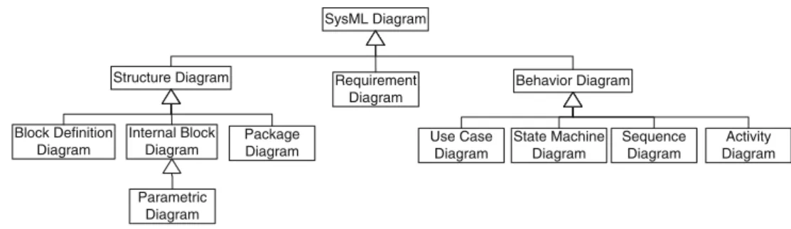
SysML Diagram
Structure Diagram Requirement Diagram Behavior Diagram Package Diagram Block Definition Diagram Internal Block Diagram Parametric Diagram Use Case Diagram State Machine Diagram Sequence Diagram Activity Diagram
Fig. 1 OMG SysML diagrams
The Function–Behavior–Structure (FBS) model proposed by Gero [22] and its recent extensions as well in multiple view modelling as in ontological application are considered as a generic model [23–26]. The described views are similar to those presented in Le Moigne’s theory [27], and in which the relationships between views lead to resolving problem phases such as formulation, synthesis, analysis, evaluation, and reformulation. Eversheim et al. [28] mentioned a model to support the integration of design and process planning in a simultaneous way. Initially, Tichkiewitch [29,30] developed a multiple view model enabling the management of prod-uct technical data for integrated design, and then improved for specific application such as the interface between prod-uct design and forging process, or in the broader context of project–product–process-usage domains [31]. From an assembly process point of view, Lohse et al. [32] defined ontology for product and assembly process domain. The NIST proposed the DPPI project in which an information model improving the communication between design and process planning during the whole product development pro-cess is described [33]. Zha and Du [34] defined a generic product assembly model using STEP and agent-based tech-niques for concurrent integrated design and assembly plan-ning. Others models such as Core Product Model (CPM) and Open Assembly Model (OAM) from NIST were developed in order to manage product lifecycle information [35,36]. The CPM model provides a generic and expandable model cap-turing the engineering context through the product lifecycle. The OAM model proposes a system and conceptual model to represent function, form, and behaviour of the product from an assembly point of view. The IPPOP project highlighted the Product–Process-Organization (PPO) model as a generic and semantic model enabling instantiation for stakeholders concerns among the product lifecycle stages [37]. Huang and Gu [38] presented a method for coupling product and process models based on an algorithm for models synchronisation. Bronvoort and Noort [39] developed a multiple view feature model supporting conceptual design, assembly design and part detail design, and part manufacturing planning phases. More recently, Bouikni et al. [40] presented a multiple views
mechanisms generation with a Product Feature Evolution Model (PFEV) model in order to control information flow in the product development process.
2.3 SysML modelling for PLM
The Systems Engineering (SE) philosophy gives an over-view of every process within the product lifecycle [41]. SE ensures a well-balanced product in consistency with disci-plines and departments requirements. Various complemen-tary standards are attached to SE in order to describe generic frames improving efficiency and flexibility in the product development process. According to EIA 632 Standard, a system is composed of one or more components related to enabling systems such as assembly systems. The relationship between various entities used in the product lifecycle such as component–component relations or function–component and component–assembly operation allocations is essential in the context of integrated product–process design. Both SE and PLM approaches are hence adapted to manage relation-ships between system elements (i.e. requirements, function, component, etc.) [42]. Therefore, the current need is based on a standard modelling language enabling a dynamical interop-erability between disciplines and domains through the prod-uct lifecycle. In such a context, Thimm et al. [43] highlighted the need in a formal modelling technique for capturing all the aspects of PLM by using the United Modeling Language (UML). The SysML paradigm developed by Object Man-agement Group (OMG) tends to unify the numerous mod-elling languages used by systems engineers, and extends the application of UML 2.0 functionalities to engineering of systems which are not purely software based [8]. SysML proposes nine diagrams (Fig.1) contained into three views (requirement, structure, and behaviour) covering information modelling at various abstraction levels through the product lifecycle.
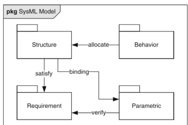
As shown in Fig.2, the SysML generic model can be repre-sented according to three packages and a parametric diagram enabling the constraint relationships between system views.
Requirement Behavior Parametric Structure allocate binding satisfy verify pkg SysML Model
Fig. 2 SysML generic model
SysML is quite appropriate in the AOD framework since it defines strategic context model associated to integrated product–process design, especially meant for information modelling in the early phases of the product development process.
The interest of the SysML results in a more flexible and expressive semantic than the UML language. In this context, the system engineer can use the SysML to express with details the requirements engineering, the performance and the quan-titative analysis. Moreover, SysML is a smaller language which makes it easy to learn and apply. From a modelling point of view, SysML provides allocation tables which sup-port common kinds of allocations. Whereas UML provides only limited support for tabular notations, SysML furnishes flexible allocation tables that will support requirements allo-cation, functional alloallo-cation, and structural allocation as well. In addition, SysML model management constructs support models, views, and viewpoints. Build on this, in the following section, a multiple viewpoint modelling framework MUVOA is proposed and described.
3 Proposed MUVOA model
Among the proposed models depicted from literature, the authors have identified a need to break down the product according to viewpoints related to stakeholders involved within the product lifecycle, and thus to separate the various concerns. Based on recent research work about inte-grated product–process design called AOD [7], the proposed model MUVOA tends to eliminate current difficulties related to competitiveness factors in engineering projects such as information exchange through concurrent activities between departments. It should be adapted to information sharing and flexibility in information propagation during the early phases of product development process, especially between the preliminary product design and assembly sequence plan-ning phases.
3.1 Assumptions
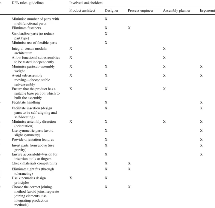
Based on current identified challenges in literature and the related AOD approach, the authors have focused on heuristic rules used in DFA approaches improving the product from an assembly point of view [4,5,10]. Twenty rules have been listed and involved five stakeholders (Table1):
• The Product architect who manages product structure and modelling context for designers,
• The designer who specifies and defines product geometry according to product lifecycle requirements and engineer-ing constraints,
• The assembly planner who specifies assembly sequences, assembly operations, and so on,
• The process engineer who guarantees and brings out all relevant information for a specific assembly process • The ergonomist who defines and analyses the assembly
operator activity during the assembly process.
Therefore, it is possible to identify each stakeholder’s viewpoint, their role and concerns in order to associate the various entities with their own view.
The consideration of DFA rules into the product develop-ment process may impact stakeholder’s concerns, such as product structure and product modelling issues related to assembly sequence definition in assembly sequence plan-ning phase. Here several assumptions are emphasised for the MUVOA model definition enabling therefore an effective integration in PLM systems. For the proposed model, the authors have considered:
• The product as the result of a top-down design process integrating activities lead by involved stakeholders in AOD approach (product architect, designer, assembly planner, process engineer, and ergonomist),
• The product as the result of assembly process operations between various parts and sub-assemblies,
• The assembly sequence definition in the early product development process in order to provide a contextual sup-port and a constraint environment for product structure and product modelling phases.
3.2 Viewpoints/views definition
Based on these assumptions, the proposed MUVOA model related to product assembly issues enables a dynamical man-agement of information to control during the early product design stages. The MUVOA model is based on the Gomes’ model called Multiple Domains and Multiple View-points (MD-MV) which is broken down in domains (pro-ject, product, process, and usage) and viewpoints (functional,
Table 1 DFA rules and related involved stakeholders
No. DFA rules-guidelines Involved stakeholders
Product architect Designer Process engineer Assembly planner Ergonomist 1 Minimise number of parts with
multifunctional parts
X
2 Eliminate fasteners X X
3 Standardize parts (to reduce part type)
X
4 Minimise use of flexible parts X
5 Integral versus modular architecture
X X
6 Allow functional subassemblies to be tested independently X X 7 Minimise part/sub-assembly weight X X X X 8 Avoid sub-assembly moving—choose stable sub-assembly X X X X
9 Ensure that the product has a suitable base part on which to built the assembly
X X X
10 Facilitate handling X X
11 Facilitate insertion (design parts to be self-aligning and self-locating)
X X
12 Minimise assembly direction (orientation)
X X X X
13 Use symmetric parts (avoid slight symmetry)
X X
14 Provide orientation features X X
15 Insert parts from above (use gravity)
X X
16 Ensure accessibility/vision for insertion tools or fingers
X X
17 Check materials compatibility X X
18 Eliminate tight fits (through tolerancing)
X X
19 Use kinematics design principles
X X
20 Choose the correct joining method (avoid joins, separate joining elements, use integrating production methods)
X X
structural, behavioural, geometric, and physical) is processed [31]. In order to structure the information exchanges dur-ing the product development process, the MUVOA model considers activities within the product lifecycle as network of business domains. In such a context, each domain cor-responds to a product lifecycle stage and is defined as a system integrating views and viewpoints. Each view repre-sents system with the perspective of a viewpoint. A view-point describes conventions and rules to build and define the related view in order to fulfil stakeholders’ concerns. A meta-model adapted from IEEE 1471 Standard [44] is
pro-posed, thus enabling the logical definition and identification of viewpoints/views and domains for the system (Fig.3).
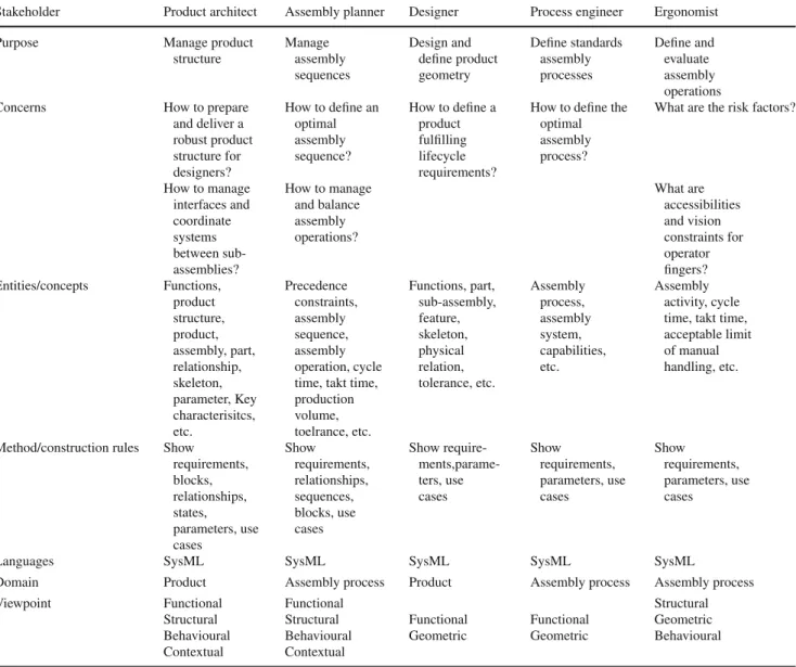
Here two domains are considered, namely the product and assembly process domains, and integrate specific views related to roles and concerns of each involved stakeholder in AOD issue (Table2). Identified views are used as the pro-jection of viewpoints highlighting purposes, concerns, and specific concepts. Construction rules are used to define view meant to realise the viewpoint.
Hence, each domain (i.e. product domain and assembly process domain) can be considered as a system with multiple
Fig. 3 Meta-model adapted
from IEEE 1471 definitions pkg Views / Viewpoints Meta-Model
System View Viewpoint Concern Model Modeling Language Stakeholder Life Cycle used to define conforms 1..* 1 1 1..* 1 1..* 1 1..* Purpose 1 1..* is a projection of abstracts 1..* 1 1 1..* 1..* 1..*
Table 2 Involved stakeholders’ profiles
Stakeholder Product architect Assembly planner Designer Process engineer Ergonomist
Purpose Manage product
structure Manage assembly sequences Design and define product geometry Define standards assembly processes Define and evaluate assembly operations
Concerns How to prepare
and deliver a robust product structure for designers? How to define an optimal assembly sequence? How to define a product fulfilling lifecycle requirements?
How to define the optimal assembly process?
What are the risk factors?
How to manage interfaces and coordinate systems between sub-assemblies? How to manage and balance assembly operations? What are accessibilities and vision constraints for operator fingers? Entities/concepts Functions, product structure, product, assembly, part, relationship, skeleton, parameter, Key characterisitcs, etc. Precedence constraints, assembly sequence, assembly operation, cycle time, takt time, production volume, toelrance, etc. Functions, part, sub-assembly, feature, skeleton, physical relation, tolerance, etc. Assembly process, assembly system, capabilities, etc. Assembly activity, cycle time, takt time, acceptable limit of manual handling, etc.
Method/construction rules Show requirements, blocks, relationships, states, parameters, use cases Show requirements, relationships, sequences, blocks, use cases Show require- ments,parame-ters, use cases Show requirements, parameters, use cases Show requirements, parameters, use cases
Languages SysML SysML SysML SysML SysML
Domain Product Assembly process Product Assembly process Assembly process
Viewpoint Functional Functional Structural
Structural Structural Functional Functional Geometric Behavioural Behavioural Geometric Geometric Behavioural Contextual Contextual
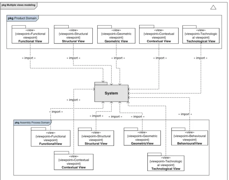
pkg Multiple views modeling System «view» {viewpoint=Functional viewpoint} Functional View «view» {viewpoint=Functional viewpoint} FunctionalView
pkg Assembly Process Domain
«view» {viewpoint=Contextual viewpoint} Contextual View «view» {viewpoint=Structural viewpoint} Structural View «view» {viewpoint=Geometric viewpoint} Geometric View «view» {viewpoint=Behavioural viewpoint} BehaviouralView «view» {viewpoint=Structural viewpoint} Structural View pkg Product Domain «view» {viewpoint=Geometric viewpoint} GeometricView
« import » « import » « import »
« import » « import » « import » « import » « import » «view» {viewpoint=Technologic al viewpoint} Technological View «view» {viewpoint=Contextual viewpoint} Contextual View «view» {viewpoint=Technologic al viewpoint} Technological View « import » « import » « import »
Fig. 4 Multiple view meta-model adapted to an integrated product–process design approach
perspectives. Six generic views have been proposed and defined in consistency with the assembly oriented design context as listed below:
• The structural view highlights the ontological consider-ation of the system,
• The functional view considers the system with its func-tions,
• The behavioural view considers the system in its temporal behaviour,
• The geometric view considers the system in its form, size, and spatial positioning,
• The contextual view considers the system in its lifecycle oriented context,
• The technological view considers the system in its achievement and execution and highlights the know-how to do this.
A SysML Package diagram is used to organise identified domains and related views for the proposed MUVOA model. This diagram presents relationships between each view in consistency with the AOD approach (Fig.4).
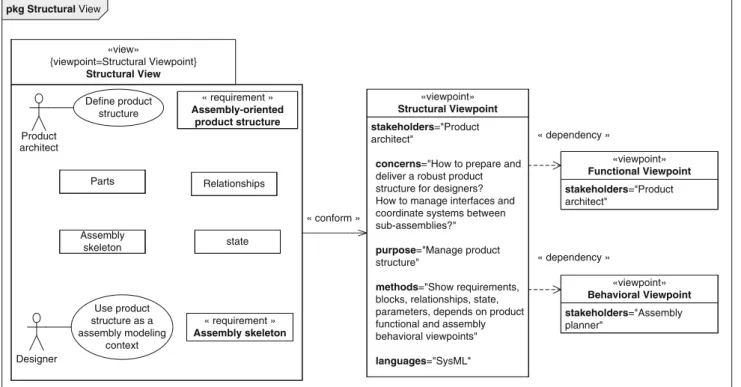
Build on this, Table2shows relevant elements that enable the definition of views. In such a context, a view is considered as a representation of a whole system or sub-system from the perspective of a single viewpoint. From the product domain, the definition of the structural view is illustrated in Fig.5in which the product architect viewpoint is described, so as to generate the related view. Besides, this view is constructed in compliance with methods and languages that are speci-fied as part of the structural viewpoint. The proposed view is allowed to import other elements including other views which are conformed to the viewpoint.
As a result, the proposed MUVOA model has been com-puted by processing and defining all views in product and
pkg Structural View «view» {viewpoint=Structural Viewpoint} Structural View Product architect stakeholders="Product architect"
concerns="How to prepare and
deliver a robust product structure for designers? How to manage interfaces and coordinate systems between sub-assemblies?"
purpose="Manage product
structure"
methods="Show requirements,
blocks, relationships, state, parameters, depends on product functional and assembly behavioral viewpoints" languages="SysML" «viewpoint» Structural Viewpoint « conform » Define product structure stakeholders="Product architect" «viewpoint» Functional Viewpoint « requirement » Assembly-oriented product structure stakeholders="Assembly planner" «viewpoint» Behavioral Viewpoint Designer Use product structure as a assembly modeling context Relationships Assembly skeleton « requirement » Assembly skeleton Parts state « dependency » « dependency »
Fig. 5 Example of structural viewpoint definition from product domain
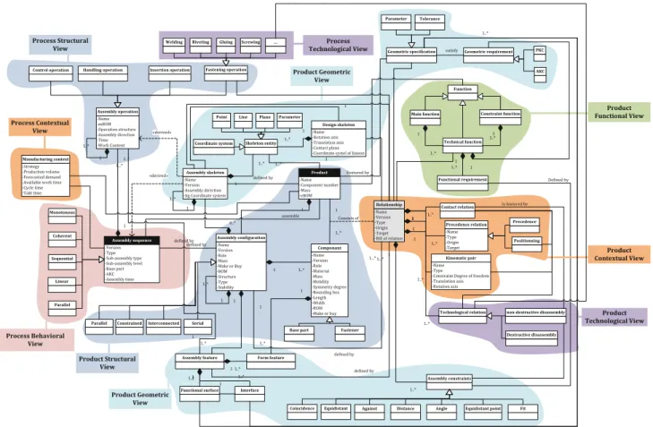
assembly process domains. The MUVOA model describes entities and their associations which are handled in the AOD approach [7]. The main objective of the model is here to map concepts and related data structures in order to be used in an integrated manner. Figure6presents the MUVOA model and the various views from product and assembly process domains. Six kinds of views have been shown to describe the various abstraction levels of information, especially at the beginning of the product lifecycle. Thus, this model highlights the complexity of relationships among different stakeholders and multiple viewpoints. Such a comprehen-sive representation will facilitate and propagate information flow towards other related views as well.
3.3 Information flow between viewpoints
In order to support the AOD approach in the context of inte-grated product–process design [7], a SysML sequence dia-gram is presented to define chronological actions between each stakeholder with a high abstraction level (Fig.7). Thus, interactions between system components in the MUVOA model are highlighted, so as to control information flow. Five stakeholders are involved in the proposed model in order to work in a concurrent and integrated way. Starting from a product breakdown structure [Engineering Bill of Materials (EBOM)] fulfilling technical functions, the product archi-tect defines relationships between product parts. Afterwards,
the assembly planner works on the defined relationships network with a mathematical algorithm to define the assem-bly sequence, assemassem-bly operations, and activities [Manufac-turing Bill of Materials (MBOM)] [7]. Based on the generated assembly sequence, an assembly context is established for the product architect with an assembly oriented product structure and later for designer with assembly skeletons. Therefore, product architect and assembly planner can work together in their specific views with specific information (EBOM and MBOM). The designer will use in its own view, generated information from all stakeholder views.
4 Implementation in a new tool
The multiple viewpoint modelling framework proposed in this paper is being fully implemented in a Web-service called PEGASUS that is considered as an application for PLM sys-tems. The programming language used for implementation is an object oriented language called C# in compliance with. Net architecture used for the legacy Web-based PLM sys-tem called ACSP (in French: Atelier Coopératif de Suivi de Projet). Indeed, product–process data and information are dispersed along a variety of information systems, therefore some expectations are related to interoperability issues. The Web-service technology enables interoperability between systems and platforms used in the AOD approach such as
Fig. 6 UML class diagram of the proposed MUVOA model
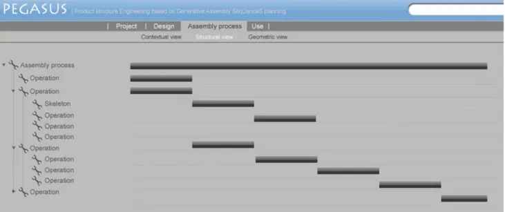
PLM and computer aided design (CAD) systems. Besides, it integrates a computational framework in order to generate automatically views starting from relevant information. The authors highlight two specific views in Figs.8and9that are the structural view from product domain and the related struc-tural and behavioural views from assembly process domain. A mathematical algorithm enables to keep closely a relation between both views.
5 Conclusion and future work
Based on current issues and challenges depicted in the litera-ture survey about DFA, product–process data modelling, and SysML, a multiple viewpoint modelling framework in com-pliance with recent work about integrated product–process design has been proposed and described. Starting from the assembly oriented design methodology proposed in [7] and DFA rules, the proposed model was built with SysML mod-elling language in order to be in coherence with Systems Engineering philosophy. The model processing is based on the use of three types of SysML diagrams (activity, sequence and use cases) to model the behavioural specifications of such an integrated approach.
Five stakeholders were identified who are product architect, designer, assembly planner, process engineer, and ergonomist. For each stakeholder, a viewpoint is defined and in compliance with product lifecycle views. The proposed model enables the consistency, the propagation of informa-tion change, and mechanisms of views generainforma-tion among the product lifecycle stages in order to support AOD approach. The implementation of the proposed model into a ser-vice called PEGASUS as an application for a legacy Web-based PLM system is described, thus ensuring assistance for each identified stakeholder and providing a wider and more effective use of product lifecycle information in the context of integrated product–process design. The product develop-ment process becomes more complex and more knowledge-intensive, thus requiring a computational framework that enables the capture and reuse of product–process knowledge. Currently the knowledge elicitation process is ensured by database inside the Web-service. As a product–process inte-gration factor, the semantic value of the MUVOA model will raise into ontology in the context of variational approach for further research work. In addition the PEGASUS Web-ser-vice will be improved by integrating new business ontologies related to the product lifecycle, so as to become a semantic Web-service [45]. Thus, such an application will enable to
Product architect Product structure Assembly sequence Assembly planner Designer Process engineer Ergonomist Create () Relationships Add () Assign () Notify () Create ()
Notify values (levels, sub-assemblies, assembly order, ...) Update () Assembly process Assembly activity Assembly skeleton Create () Use () Define () Define () Notify () Notify () Create () Create () Define () Define ()
Notify values (line, plane, swept volume, ...)
Update ()
Fig. 7 Example of SysML sequence diagram representing information flow between each stakeholder with a high abstraction level and in com-pliance with AOD approach [7]
Fig. 9 Structural and behavioural views from assembly process domains according to the assembly planner point of view implemented in PEGA-SUS web-service prototype
improve communication and information exchange through PLM Systems and to ensure interoperability between several business applications.
Acknowledgments The research activity is a part of the CoDeKF Research Project (Collaborative Design and Knowledge Factory) which has been funded by the French Automotive Cluster ‘Pôle de Compétiti-vité Véhicul du Futur’. The authors will thank all the financial supports of this research and technology program: DRIRE de Fran-che-Comté, Communauté d’Agglomération du Pays de Montbéliard, Conseil Général du Doubs and Conseil Régional de Franche-Comté.
References
1. Wiendahl, H.-P., ElMaraghy, H.A., Nyhuis, P., Zäh, M.F., Windahl, H.-H., Duffie, N., Brieke, M.: Changeable manufacturing—classi-fication, design and operation. Ann. CIRP 56(2), 783–809 (2007) 2. Subrahmania, E.: The NDIM approach to creating design sup-port systems. DETC’97/DTM-3873 ASME Technical Conference, Sacramento, California, September (1997)
3. Srinivasan, V.: An integration framework for product lifecycle management. Comput. Aided Des. (in press) (2009)
4. Boothroyd, G., Dewhurst, P., Knight, W.: Product Design for Manufacture and Assembly. pp. 698 s, 2nd edn. Marcel Dekker, New York (2002)
5. Andreasen, M.M., Kähler, S., Lund, T.: Design for Assem-bly. pp. 211 s 2nd edn. IFS Publications, London (1983) 6. Huang, G.Q., Lee, S.W., Mak, K.L.: Web-based product and
pro-cess data modeling in concurrent “design for X”. Robot. Comput. Integr. Manuf. 15, 53–63 (1999)
7. Demoly, F., Yan, X.-T., Eynard, B., Rivest, L., Gomes, S.: An assembly-oriented design framework for product structure engi-neering and assembly sequence planning. Robot. Comput. Integr. Manuf. (corrected proof). doi:10.1016/j/rcim.2010.05.010(2010) 8. SysML Partners: Systems Modeling Language: SysML. http://
www.omg.org/cgi-bin/doc?ad/04-08-03(2004)
9. Huang, G.Q. (eds.): Design for X-Concurrent Engineering impera-tives. Chapman & Hall, London, pp. 153–172. ISBN 0-402-78750-4 (1996)
10. Redford, A., Chal, J.: Design for Assembly, Principle and Prac-tice. McGraw-Hill Book Company, Europe (1994)
11. Miyakawa, S., Shigemura, T.: The Hitachi assemblability eval-uation method (AREM). In: Proceedings of the Japan Society of Mechanical Engineering Conference on Manufacturing Sys-tems and Environment Looking Toward 21st Century, pp. 277–282 (1990)
12. Lucas Engineering Systems Ltd: Design for manufacture and assembly practitioners manual. Version 10 (1993)
13. Stone, R.B., McAdams, D.A., Kayyalethekkel, V.J.: A product architecture-based conceptual DFA technique. Des. Stud. 25, 301– 325 (2004)
14. Barnes, C.J., Jared, G.E.M., Swift, K.G.: Decision support for sequence generation in an assembly oriented design environ-ment. Robot. Comput. Integr. Manuf. 20(4), 289–300 (2004) 15. Whitney, D.E., Nevins, J.L., De Fazio, T.L.: The strategic approach
to product design. In: Design and Analysis of Integrated Manufac-turing Systems, pp. 200–223 (1988)
16. Lee, S., Shin, Y.G.: Assembly co-planner: cooperative assembly planner based on subassembly extraction. J. Int. Manuf. 4(3), 183– 198 (1993)
17. Pu, P.: An assembly sequence generation algorithm using case-based search techniques. In: IEEE International Conference on Robotics Automation, Nice, France, pp. 2425–2429 (1992) 18. Daabub, A.M, Abdalla, H.S.: A computer-based intelligent system
for design for assembly. Comput. Ind. Eng. 37, 111–115 (1999) 19. Mascle, C.: Feature-based assembly model for integration in
com-puter-aided assembly. Robot. Comput. Integr. Manuf. 18, 373– 378 (2002)
20. Zha, X.F., Lim, S.Y.E., Fok, S.C.: Integrated intelligent design and assembly planning a survey. Int. J. Adv. Manuf. Technol. 14, 664– 685 (1998)
21. Yan, X-T., Eynard, B., Ion, W.J. (eds.): Global Design To Gain A Competitive Edge: An Holistic And Collaborative Design Approach Based On Computational Tools. Springer, Berlin (2008)
22. Gero, J.S.: Design prototypes: a knowledge representation scheme for design. AI Mag. 11, 26–36 (1990)
23. Rosenman, M.A., Gero, J.S.: Modelling multiple views of design objects in a collaborative CAD environement. Comput. Aid. Des. 28(3), 193–205 (1996)
24. Gero, J.S., Kannengiesser, U.: A Function-Behavior-Structure ontology of processes. Artif. Intell. Eng. Des. Anal. Manuf. 21(2), 379–391 (2007)
25. Labrousse, M., Bernard, A. : FBS-PPRE, an enterprise knowledge lifecycle model. In: Bernard, A., Tichkiewitch, S. (eds.) Meth-ods and Tools for Effective Knowledge Life-Cycle-Manage-ment, pp. 285–305. Springer, Berlin (2008)
26. Umeda, Y., Ishii, M., Yoshioka, M., Shimomura, Y., Tomiyama, T.: Supporting conceptual design based on the function-behavior-state modeler. Artif. Intell. Eng. Des. Anal. Manuf. 10(4), 275– 288 (1996)
27. Le Moigne, J-L.: La théorie du Système Général, théorie de la modélisation. P.U.F., Paris, 1977, 3ième édition mise à jour (1990) 28. Eversheim, W., Rozenfeld, H., Bochtler, W., Graessler, R.: A meth-odology for an integrated design and process planning based in concurrent engineering reference model. Ann. CIRP 44(1), 403– 406 (1995)
29. Tichkiewitch, S.: Specifications on integrated design methodology using a multi-view product model. In: System Design and Analysis Conference, Montpellier, pp. 101–108 (1996)
30. Tichkiewitch, S., Véron, M.: Integration of manufacturing pro-cesses in design. Ann. CIRP 47(1), 99–102 (1998)
31. Gomes, S., Sagot, J-C.: A concurrent engineering experience based on a cooperative and object oriented design methodology. In: Best papers Book from 3rd International Conference on Integrated Design and Manufacturing in Mechanical Engineering. Kluwer, Dordrecht (2002)
32. Lohse, L., Hirani, H., Ratchev, S., Turitto, M.: An ontology for the definition and validation of assembly processes for evolvable assembly systems. In: The 6th IEEE International Symposium on Assembly and Task Planning: From Nano to Micro Assembly and Manufacturing, pp. 242–247 (2005)
33. Nederbragt, W., Allen, R., Feng, S., Kaing, S., Sriram, R., Zhang, Y.: The NIST design/process planning integration project. In: Pro-ceedings of the Artifical Intelligence and Manufacturing Work-shop, pp. 135–139 (1998)
34. Zha, X.F., Du, H.: A PDES/STEP-based model and system for concurrent integrated design and assembly planning. Comput. Aid. Des. 34, 1087–1110 (2002)
35. Fenves, J.: A core product model for representing design informa-tion, USA. National Institute of Standards and Technology, NISTIR 6736, Gaithersburg, MD 20899, USA (2001)
36. Sudarsan, R., Fenves, S.J., Sriram, R.D., Wang, F.: A product information modeling framework for product lifecycle manage-ment. Comput. Aid. Des. 37, 1399–1411 (2005)
37. Noël, F., Roucoules, L.: The PPO design model with respect to digi-tal enterprise technologies among product life cycle. Int. J. Comput. Integr. Manuf. 21(2), 139–145 (2008)
38. Huang, H.Z., Gu, Y-K.: Development mode based on integra-tion of product models and process models. Concurr. Eng. Res. Appl. 14(1), 27–34 (2005)
39. Bronsvoort, W.F., Noort, A.: Multiple-view feature modeling for integral product development. Comput. Aid. Des. 36, 929– 946 (2004)
40. Bouikni, N., Rivest, L., Desrochers, A.: A multiple views manage-ment system for concurrent engineering and PLM. Concurr. Eng. Res. Appl. 16(1), 61–72 (2008)
41. INCOSE-TP-2003-016-02: Systems engineering handbook. INCOSE Technical Product (2004)
42. Bock, C.: Systems engineering in the product lifecycle. Int. J. Prod. Dev. 2(1), 123–137 (2005)
43. Thimm, G., Lee, S.G., Ma, Y.-S.: Towards unified modeling of product life-cycles. Comput. Ind. 57, pp. 331–341 (2006) 44. Koning, H., Vliet, H.van : A method for defining IEEE Sdt 1471
viewpoints. J. Syst. Softw. 79, 120–131 (2006)
45. Agarwal, S., Handschuh,S., Staab, S.: Annotation, composition and invocation of semantic web services. J. Web Semant. 2, 31–48 (2004)