Degree Programme
Systems Engineering
Major Infotronics
Bachelor’s Thesis
Diploma 2017
Chalokh Sara
XF operating system
Professor M e d a r d R i e d e r Expert P a t r ic k Am b o r b Submission date of the report 2 5 . 0 8 . 2 0 1 7P a g e
2|
76Project summary
The Embedded Communication System group (ECS Group) dispose on its own developed Execution Framework (XF). This actual version is not adapted for a real-time operating system (OS) such as Free RTOS, Zephir-OS or similar.
This Bachelor thesis has for purpose to develop, test and document an XF than can be put on the top of an OS or RTOS. The interface of the XF should not depend on the used OS it must therefore implement an operating system abstraction layer (OSAL)
This document presents the specifications of the project, a brief description of the actual execution framework, an analysis of the Free RTOS primitives and a first solution to mix them. Then will come the development of the project and the tests realized.
P a g e
3|
76Table des matières
I. Project summary ... 1
II. List of acronyms ... 5
III. Introduction ... 6
IV. The actual execution framework ... 7
1. What is an execution framework? ... 7
2. How work the ECSG XF ... 8
The processing of an event... 8
The timeout manager ... 9
V. Free RTOS primitives ... 11
taskHandle_t ... 11
queueHandle_t ... 11
TimerHandler_t ... 12
SemaphoreHandle_t ... 13
VI. Solutions ... 14
1. Differences with the ECSG XF ... 15
Timeout and Events ... 16
2. Error Handling ... 17
Functions that already return a value ... 18
The problem of constructors ... 18
Errors and ErrorHandler... 18
3. Inter-task communication ... 18
4. The XFOS_config.h ... 19
Specific variables type ... 19
Defined values ... 20 VII. Architecture ... 21 1. OSAL Package ... 22 Queue ... 22 Semaphore ... 24 Binary Semaphore ... 25 Mutex ... 25 BaseThread ... 26 ITimer ... 30 5. XF package ... 33 Thread ... 33 TimerManager ... 34 Event ... 38 EventDelay ... 40 IStateMachine ... 41
P a g e
4|
76StateMachine ... 41
ErrorHandler ... 42
Error ... 42
VIII. Tests ... 43
1. Normal event processing test ... 43
6. Delay event processing test ... 44
7. Cancel event test ... 46
8. Multi state machines Mono thread test ... 48
9. Multi state machine Multi thread test ... 50
10. Inter-state machine communication ... 52
In the same thread ... 53
In different threads ... 54
11. Priority Thread ... 55
12. Error handler test ... 57
13. Mutex, semaphore test ... 57
14. Timing precision ... 59
IX. Google test code analyse ... 65
1. Utility of google test ... 65
2. Problems encountered ... 65
Solving problems ... 66
3. Conclusion about gtest ... 68
Solution proposed ... 68
X. Future adaptations ... 69
1. Adaptation for others operating systems ... 69
Others OSAL ... 69 IDF ... 69 2. Priority thread ... 72 Solution ... 73 XI. Conclusion ... 74 XII. Bibliography ... 75 XIII. Annexes... 76
P a g e
5|
76II. List of acronyms
Acronym Real word
API Application Programming Interface
ECSG Embedded Communication Systems Group
gtest Google test
OS Operating System
OSAL Operating System Abstraction Layer
RTOS Real Time Operating System
UART Universal Asynchronous Receiver Transmitter
XF eXecution Freamwork
P a g e
6|
76III. Introduction
This project takes place in the embedded system programming, an increasingly domain in the world of today. The embedded system programming is purely informatics, but it needs strong skills in electronic to understand exactly the work of the system. Low resources offered by embedded system impose strong constraints on the processing time, memory usage, power consumption and security. In parallel embedded systems must carry out more and more complex tasks.
To carry out their work, many embedded systems realize a series of actions depending on a sequence of events with which they are presented. This series of actions is named a state machine. Most of embedded systems uses this concept because it separates the work into a set of simple tasks. Nowadays, the operating systems used in the embedded systems are not adapted to execute state machines. The programming concept used to execute state machines is the execution framework.
The goal of this project is to developpe or adapt an operating system to make it can execute state machines.
The Embedded Communication System Group (ECS Group) working in the HES-SO Valais/Wallis has developed its own execution framework. But this one works without any operating system. It means that it could not work with an OS or RTOS and, thereby, cannot enjoy the benefits offered by a real OS. Such as, multi-threading, memory management or mutual exclusion.
This project aims to develop an execution framework to put on the top of the real-time operating system Free RTOS. The programming language used is the C++, a language very used in the embedded system world and that is object oriented. The project must be developed in order to be adapted for other operating systems. Therefore, it must propose an operating system abstraction layer.
In the beginning, the new XFOS should have been implemented on the base of an ARMEBS4 (cortex M4F), but during the project, it has been changed to the STM32F412 Discovery kit from ST Microelectronics.
All new elements and programmer interfaces should be presented in the form of a set of UML diagrams.
Every solution must be tested and documented.
Finally, a complete documentation must be established, this include: • A WIKI documentation for the new XFOS
• A complete unity test for every solution using Google test • A final report
P a g e
7|
76IV. The actual execution framework
1. What is an execution framework?
An XF provides a collection of services that allow asynchronous communication and execution of objects and of reactive entities containing state machines [1]. When XF is used with an OS, it is an abstraction layer between the OS and the user’s applications. When it is used without OS, it is an interface and provides some important functions of an OS such as synchronization, pseudo parallel execution and a high abstraction degree.
The XF offers a simple interface that do not depend of a specific OS, it allows methods to implement state machines, that is very adapted to embedded requirements. The code size of an XF is small and it can be developed in any programming language.
The Figure 1 presents the class diagram of all the XF.
P a g e
8|
762. How work the ECSG XF
The ECSG XF works with the combination of State machines (XFReactive) these will execute some code and move forward the program, and Events that will change the actual state of the state machine.
State machines contain the core of the application developed by the user.
Events are sent to the thread (XFThread) by state machines when they have finished executing the code of their actual state. One time sent by state machines, events are stored in a queue and wait to be processed.
When an event is processed, it is sent to the state machine and this one (in function of the information of the event and the actual state) will change its actual state and execute the code of the new state.
Some events could need a delay before being processed. To do this, the XF uses a timeout manager and timeouts. In the ECSG XF, when state machines would send an event with a delay they must call the timeout manager and schedule a timeout. When the time specified ends, the timeout manager will notify the state machine that a timeout occurs.
The processing of an event
The ECSG XF is made of one thread where are living all state machines, and an event queue that contains events of state machines. To execute state machines, the XF reads the first event of its event queue and dispatch it to the good state machine. When a state machine receives an event, it goes in a new state and executes its code, finally the state machine sends a new event to the event queue to start the next state.
At the begin all state machines are in an initial pseudo state and they send an initial event to start.
The sequence diagram of the Figure 2 presents this process.
P a g e
9|
76The timeout manager
The ECSG XF offers the possibility to use timeouts. Timeouts are special events that have a delay before being sent to the state machine. Timeouts are managed by a timeout manager. This one contains a timeout queue where are stored all active timers. When a timer ends, the timeout manager notifies the state machine that push the event to the event queue.
Figure 3 : the ECSG XF processing of a timeout
The management of timeouts
The creation of an independent timer in an embedded system is not possible because the number of hardware timers is limited. Another solution is to use only one hardware timer with a short period (tick) and update all software timers of the timeout list. This solution is right but it poses a problem because the time to update all timers depend on the number of timers in the queue, this is not acceptable for a real-time system.
The method proposed in the ECSG XF is to use timeouts with 2 values:
• timeoutTicks: the time to wait in tick (ticks are the hardware timer’s period) • remainingTicks: the number of tick to wait before the timer timeout
The difference with the second solution takes place when a timer is added in the queue, instead of adding the timer at the end of the queue, the timer manager will browse the queue and search the first timer that the number of remainingTicks is lower than the timeoutTicks of the timer to add. Once found the timeout manager adds the new timer just before it and update the remainingTicks of the new timer.
Figure 4 : How and where add a new timer in the ECSG XF Source: XF optimized timer management, ©HES-SO Valais/Wallis [2]
P a g e
10|
76 The timeout list is updated every tick, but in the 3rd solution, only the first timer of the queueis decremented. If the remainingTick of the first timer is 0, also the timeout manager notifies the state machine.
P a g e
11|
76V. Free RTOS primitives
To develop the execution XFOS, the Free RTOS primitives needed are: • taskHandle_t: the thread of Free RTOS
• queueHandle_t: queues that can be used for an inter-task communication • timerHandle_t: a software timer from Free RTOS
• semaphoreHandle_t: a semaphore (or mutex) from free RTOS
taskHandle_t
An application that uses an OS is structured as a set of tasks that are independent. All these tasks have their own context, their own stack and their own main function. Only one of them can be executed in the processor at any point of time. The scheduler is responsible for deciding which task is executed at a given time.
The taskHandle_t is an independent task that is scheduled by the Free RTOS scheduler. A taskHandle_t has its own stack and when a task is swapped, the processor’s context (register values, stack contents, etc) is saved on the top of this stack, so it can be exactly restored when the task is later swapped back.
A taskHandle_t could be stopped after a certain amount of time of the processor usage or if it tries to access a used resource.
queueHandle_t
Queues are, in Free RTOS, the primary form of inter-task communication. It can be used to send messages between tasks or between tasks and interrupts. In Free RTOS, queue messages are sent by copies, it means that the data is itself copied into the queue rather than the queue always storing just a reference to the data.
P a g e
12|
76 Free RTOS queues offer also the possibility to suspend or wake up a task. For example, if a task tries to read a queue and this one is empty, the task will automatically wait until a message arrives in the queue.Figure 7 : Task waiting for a queue
In Free RTOS, it is possible to define a maximal amount of time that a task that need to use a queue must wait in the waiting state. If this time expired, the function will just return a value that indicates that the operation fails.
TimerHandler_t
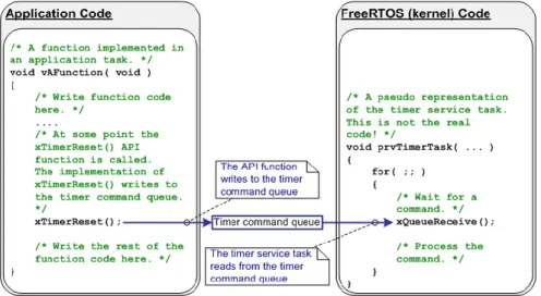
TimerHandle_t is a software timer, it allows a function to be executed at a set time in the future. This function is called a callback function. In the Free RTOS implementation timers do not use any processing time unless a timer has expired, it does not execute callback function in an interrupt context and does not add any processing time to the tick interruption [3]. All timers use the timer service task. This task is private to the Free RTOS implementation and cannot be accessed directly. It manages all timers and tries to use minimal resources. The Free RTOS API provide a set of functions to manage timers. Many of these functions use a simple Free RTOS queue to send timers to the timer service task.
Figure 8 : The call of a Free RTOS timer function
P a g e
13|
76SemaphoreHandle_t
The SemaphoreHandle_t is the base used by Free RTOS to implement counting semaphore, mutex and binary semaphore. They are used to protect critical sections and implement a synchronization.
In Free RTOS, it is possible to define a maximal amount of time that a task that need to take a semaphore must wait in the waiting state. If this time expires, the function will just return a value that indicates that the operation fails.
Counting semaphore
A counting semaphore is created by calling xSemaphoreCreateCounting(). A counting semaphore is the classic semaphore used to allow a resource to a defined number of users.
Binary semaphore and mutex
Binary semaphore and mutex are semaphores initialized to 1. Binary semaphores and mutexes are very similar but they present some subtle differences. Mutexes include a priority inheritance mechanism, binary semaphores do not. It means that the priority of a task that 'takes' a mutex can potentially be raised if another task of higher priority attempts to obtain the same mutex. The task that owns the mutex 'inherits' the priority of the task attempting to 'take' the same mutex. This means the mutex must always be 'given' back - otherwise the higher priority task will never be able to obtain the mutex, and the lower priority task will never 'disinherit' the priority. This makes binary semaphores the better choice for implementing synchronization (between tasks or between tasks and an interrupt), and mutexes the better choice for implementing simple mutual exclusion [5]
P a g e
14|
76VI. Solutions
The primary difficulty of this project is to use Free RTOS primitives in a C++ project, because Free RTOS is coded in C. To simplify, all Free RTOS primitives are encapsulated in C++ objects. These objects provide an interface to manage primitives. This approach greatly simplifies the development for some others OS because only classes that uses OS primitives must be changed. For the user, the interface does not change from an OS to another.
The Figure 9 present the solution for the implementation of the XFOS.
Figure 9 : XFOS implementation
The package XF OSAL is the part implemented to abstract the OS primitives. This part is independent from the XF work.
The package XFOS implements classes used to make the XF works. It is very different from the ECSG XF, but some classes just change name, their work is the same as the XF.
P a g e
15|
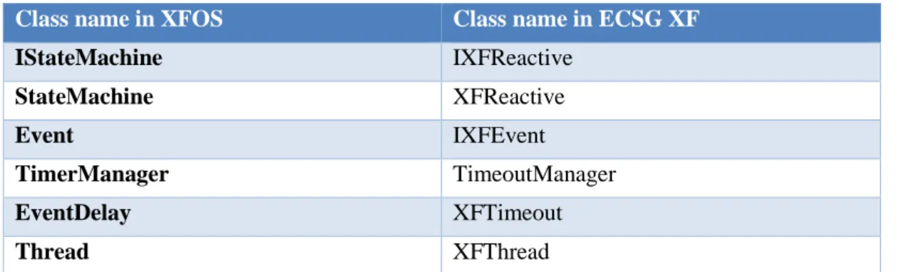
76 The Table 1 presents classes that have changed their name.Class name in XFOS Class name in ECSG XF
IStateMachine IXFReactive StateMachine XFReactive Event IXFEvent TimerManager TimeoutManager EventDelay XFTimeout Thread XFThread
Table 1 : Name changement between XFOS and ECSG XF
Some classes do not exist in the ECSG XF that are: ErrorHandler, Error and StateMachineDirectory. These classes are presented in section 2 and 3 of this chapter.
1. Differences with the ECSG XF
The principal difference between ECSG XF and XFOS is the multitasking. In the XF all state machines (behaviors) leave in the same thread. With the XFOS, state machines can be in different threads (but several state machines can still live in the same thread). A thread has its own event queue shared by all state machines that live on it.
P a g e
16|
76Timeout and Events
In the ECSG XF, Timeouts are different from simple events. State machines have to use a special function in order to use a timeout.
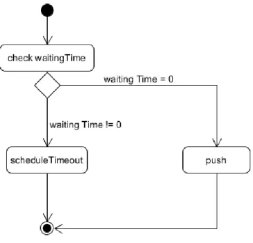
In the XFOS timeout has been removed and events could now have a delay time. It’s the work off the thread, to determine if the event must be sent to the timer manager or directly push in the event queue, when a state machine asks to add an event. This method is simpler for the user because he just need to set delay time to 0 if he does not want a delay.
The operating is presented in Figure 11.
Figure 11 : XFOS thread, add an event to the event queue
When an event with a delay is asked by a state machine, the thread must call the private method schedule timeout. This method calls the timer manager to schedule a timeout. The thread sends to the timer manage a pointer to the event that needs a delay.
The Figure 12 shows the pushing of an event with delay
Figure 12 : XFOS, addition of an event with delay
When the delay time has expired, the timer manager notifies the destination thread. This one will set the delay of the event to 0 and push it to the event queue.
P a g e
17|
762. Error Handling
During the calling of some functions, it may be something unexpected. For example, if a thread is created but there is no memory space for it.
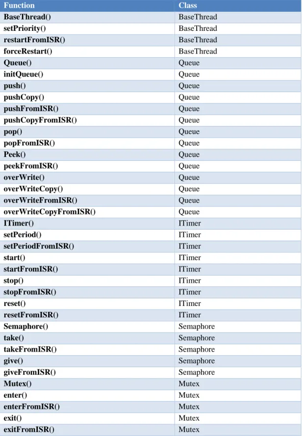
The Table 2 presents the list of functions those could not execute themselves correctly.
Function Class BaseThread() BaseThread setPriority() BaseThread restartFromISR() BaseThread forceRestart() BaseThread Queue() Queue initQueue() Queue push() Queue pushCopy() Queue pushFromISR() Queue pushCopyFromISR() Queue pop() Queue popFromISR() Queue Peek() Queue peekFromISR() Queue overWrite() Queue overWriteCopy() Queue overWriteFromISR() Queue overWriteCopyFromISR() Queue ITimer() ITimer setPeriod() ITimer setPeriodFromISR() ITimer start() ITimer startFromISR() ITimer stop() ITimer stopFromISR() ITimer reset() ITimer resetFromISR() ITimer Semaphore() Semaphore take() Semaphore takeFromISR() Semaphore give() Semaphore giveFromISR() Semaphore Mutex() Mutex enter() Mutex enterFromISR() Mutex exit() Mutex exitFromISR() Mutex
P a g e
18|
76 If one of those functions does not work as expected, it is important to inform the user. Therefore, they return a Boolean value that indicates if the function is correctly executed or not.Return a Boolean value is not a bad idea but some functions on the Table 2 could not do it because they are constructors or they already return a value.
Functions that already return a value
These functions are not numerous they are only pop(), peek() and their derivatives. Those functions will simply return NULL if they cannot execute themselves correctly.
It is the work of the user to check if a function execute itself as expected.
The problem of constructors
Constructors do not return anything, so it is not possible to inform the user that something goes wrong. To solve this problem, all classes of with a constructor can work badly have a function isCreated() that will return a Boolean value to inform if the object has been created successfully.
Errors and ErrorHandler
The solutions presented before can indicate that something does not work as expected but they cannot tell precisely the source of the problem, so it is difficult to the user to solve the problem. The best way to solve this problem would have been to use exceptions. But exceptions are not optimized for embedded systems.
So, the XFOS, in addition to implementing solutions presented before, also propose its own exceptions.
Errors are sent to the ErrorHandler by classes when something goes wrong. They contain some information about the problem that occurs to describe it more precisely.
The ErrorHandler is a thread with a higher priority than user thread. It can receive errors and execute some actions in consequence. Actions executed by the ErrorHandler are defined by the user. So, if he wants to use the ErrorHandler, he must create a subclass that inherits from it.
The user can define if he wants to use Errors and ErrorHandle in the XFOS_config.h. He just must comment or uncomment the line #define useErrorHandler.
3. Inter-task communication
The ECSG XF do not permit the inter-state machine communication. A state machine could only send an event to itself (except if it specifically knows the other state machine).
The XFOS propose a dynamic solution to send events between state machines. Whether they are in a same thread or in 2 different threads. This solution is the StateMachineDirectory. This class contains a list of pointers on all state machines. When a state machine is created, it is automatically added in the list and when it is deleted it is automatically removed from the list. Every state machine could access to this directory and thus communicate with any other state machine.
The user has the possibility to disable the StateMachineDirectory. To do this, just comment the line #define useStateMachineDirectory in the file XFOS_config.h.
P a g e
19|
764. The XFOS_config.h
The XFOS uses some variable type specific to itself and some defined values. All these values are defined in the XFOS_config.h file.
Specific variables type
The specific variable types are mainly used to minimize the use of the memory. Those types are not different from the other basic types, they just replace an existing type by using a define. The Table 3 presents all special types used in the XFOS and a definition of them.
Special XFOS type Real type Definition
timeSize TickType_t The integer value used to define a time
baseInt int32_t The basic integer value
baseUInt uint32_t The basic unsigned integer value
QUEUE_LENGHT_SIZE uint8_t The value defined to fit the maximal queue
length
ID_SIZE uint16_t The value defined to fit the maximal ID
length
PRIORITY_SIZE uint8_t The value defined to fit the maximal priority
level
STACKSIZE_SIZE uint16_t The value defined to fit the maximal stack
size
Table 3 : XFOS special types
The uppercase types are linked to the other defined values. For example, QUEUE_LENGHT_SIZE is linked to the defined value MAX_QUEUE_LENGHT. If MAX_QUEUE_LENGHT is set as 100 also an uint8_t suffice to fit it. If it is set as 500 an uint16_t is needed.
There is no maximal value defined for the ID so it is the maximal value of ID_SIZE that defines it. For example, if ID_SIZE is set as uint8_t, the maximal ID is 255.
P a g e
20|
76Defined values
Defined values are used to make the XFOS independent from a specific OS. They can be defined by the user in the file XFOS_config.h.
The Table 4 shows all defined values used, their real value in the project and a definition of them.
Define Value of the define Definition
MAX_QUEUE_LENGTH 100 The maximal number of objects
that a queue can contain simultaneously
THREAD_STACK_SIZE 128 The minimal size of the thread’s
stack (in words !!!)
LOW_PRIORITY 0 The minimal priority
MAX_USER_PRIORITY 5 The maximal priority that a user
application can have
MAX_SYSTEM_PRIORITY 10 The maximal priority that a
system application can have
INFINIT_TIME portMAX_DELAY Used to define a time that is
infinite
TIMER_QUEUE_LENGTH 10 The maximal number of timer that the timer queue can contain simultaneously
P a g e
21|
76VII. Architecture
This section describes all classes of the project, it will explain their implementation and every choice that has been made.
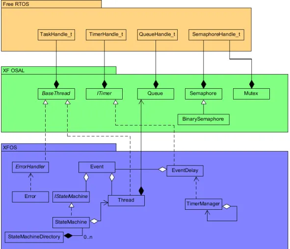
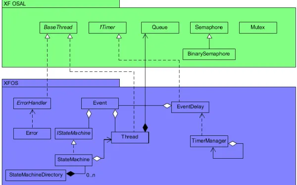
The block diagram of the Figure 13 shows all basic classes and their connections.
Figure 13 : Class Diagramm of the XFOS
Classes in the XFOSAL package directly depends of the Free RTOS primitives and must be reimplemented if another OS is used.
Finally, classes in XF package are OS independents and does not need to be reimplemented. All classes of XFOSAL and XF will be described more precisely in the remainder of this document.
P a g e
22|
761. OSAL Package
Classes of the OSAL package are interfaces to manage Free RTOS objects. These classes need to be reimplemented if another OS than free RTOS is used or if the XF must be used as an IDF.
Queue
Queue is a central element of the XFOS. It is used by Threads to store events that are waiting for a processing. It is also used by ErrorHandler to handle errors that can occur during the execution.
At the beginning Queues was designed only for the use of the XFOS and they could contain only Events, but this approach was too much restrictive for the user.
For example, if the user does not want to use Event provided by XFOS but its own type of Events, he cannot.
This is why, it has been decided that queue could contain everything.
The implementation of this class is very simple, it just contains a private attribute QueueHandle_t (the Free RTOS queue) and all its method just call Free RTOS function for it. The class diagram of the Figure 14 shows the class Queue and all its methods.
P a g e
23|
76Pointer queue and copy queue
Queue can contain copies of elements or pointers to elements.
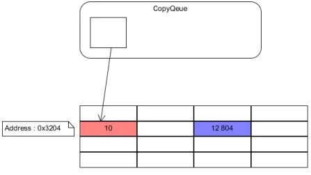
The Figure 15 shows the difference between pointer queue and copy queue. The element to push is in the red square and the blue square is where the element is popped.
Figure 15 : Pointer Queue and Copy Queue
With the pointer queue, only a pointer to the element is pushed in the queue. Depend on the size of the element this method needs less memory than using copy, but if the elements is deleted the memory pointed by the pointer in the queue is wrong. It can result in a bad memory access and a hard fault in the worst case.
With the copy queue the element is pushed by copy this means that if the element is deleted it does not affect the copy in the queue. But if the element is changed after he has been pushed the copy is not affected.
Using a pointer queue or a copy queue implies that the push action is different, to push an element in a pointer queue the user must use the method push else he must call pushCopy. What happen if user tries to use push on a copy queue?
It’s a pointer to the element that is pushed in the queue and when he tries to pop it the value is totally wrong because it’s a pointer.
The Figure 16 describes what happen if the element to push is an int. Red square (its address is 0x3204) is the element to push and blue square is where the element is received.
Figure 16 : Method push in a copy queue
P a g e
24|
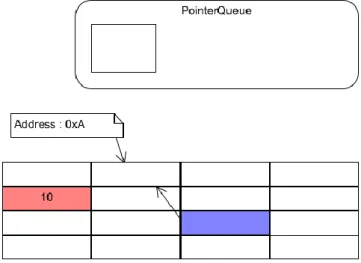
76 What happen if user tries to use pushCopy on a pointer queue?In this case the element popped is considered as a pointer but the queue contains an element so the popped value will point in a random place in the memory as shown in the Figure 17
Figure 17 : Method pushCopy in a pointer queue
Semaphore
Semaphores are essential elements for a multi-task application. Also, if they are not used for the implementation of the XFOS, the class Semaphore has been implemented for the user application. As for the Queue, Semaphore just use Free RTOS function and adapt them for a C++ object.
Figure 18 is the class Diagram of the semaphore.
P a g e
25|
76Binary Semaphore
Binary Semaphore is semaphore that can be taken only once. This is very like Mutex but Mutex include a priority inheritance mechanic. Binary semaphore not.
Binary semaphores are principally used to implement synchronization (between tasks or between tasks and an interrupt).
Binary semaphores are not used in XFOS implementation but they have been developed for user applications.
Figure 19 : Class diagram of Binary Semaphore
Mutex
Mutexes are like BinarySemaphores but they include an inheritance mechanism. This means that if a high priority task blocks while attempting to obtain a mutex (entered) that is currently held by a lower priority task, the priority of the task holding the token is temporarily raised to that of the blocking task. This mechanism is designed to ensure the higher priority task is kept in the blocked state for the shortest time possible, and in so doing minimize the 'priority inversion' that has already occurred [5].
This mechanism make that Mutexes are the best choice for implement mutual exclusion and protect critical sections.
Methods used to take and give the mutex have been named respectively enter and exit (because we enter in a critical section and we exit from it)
Mutexes are not used in the XFOS implementation but they have been implemented for the user application.
P a g e
26|
76BaseThread
This class is a C++ version of Free RTOS tasks, it is an interface that implements all Free RTOS functions to manage a Free RTOS task.
BaseThread implements also the main function of the thread, but in this class, it is just a pure virtual function that needs to be implemented on a sub class.
The Figure 21 shows all methods and attributes of the class BaseThread.
In a normal usage of the XFOS, this class should not be used directly by the user, because it is just an interface with Free RTOS.
If the user wants to create its own XFOS thread use the class Thread. This one provides specific methods for manage events and state machines. Else if the user does not want the XFOS but just want to use Free RTOS with C++ objects, this class is very useful.
P a g e
27|
76ThreadMainWrapper
The Free RTOS tasks always need a function that will be the main function of it. But this function is just a simple C function that can be called from everywhere.
In C++, it is possible to define methods for a class. So, it is better if the main function of a thread is a method of this thread.
The problem is that the thread main function need to be with a "C" linkage [6].
Therefore, it could not be a simple member function. It can only be, in the better way, a static member function.
Using a static member function is not a good way because it means that every thread has the same main function (same sub classes) and it is not the goal.
To solve this problem, it exists 2 solutions: • Using the callback method pattern
• Using a void pointer that points to the object thread
P a g e
28|
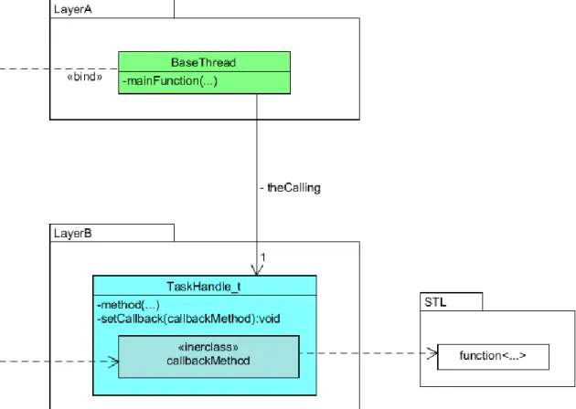
76Callback method pattern
The callback method pattern provides a lightweight callback mechanism between different layers. It offers a maximum decoupling between layers and is very safe for the application [7]. This pattern is very similar to the observer pattern.
In the context of the thread this pattern could be represented in the Figure 23.
Figure 23 : Implementation of callback method pattern in BaseThread
This implementation present real problems:
• It needs to use C++ classes, but TaskHandle_t is not a class. It is just a pointer to something that Free RTOS names a task.
• It needs to implement functions on both classes. But TaskHandle_t is an internal "pseudo-class" of Free RTOS and same if it is possible to change the Free RTOS code it is not the goal of this work.
P a g e
29|
76Using a void pointer to the BaseThread
The Free RTOS main function of the thread offers the possibility to use a void* parameter (pvParameter). The particularity of a void* pointer is that it can point on everything (same a C++ object). This parameter is set in the creation of the Free RTOS task.
It is also possible to have a static member function (the Wrapper) that get a pointer to a thread and call the main function of this thread (The function threadMain() in the present case). The Figure 24 explains that in a set of diagrams.
Figure 24 : The thread main wrapping
To resume, when the BaseThread subclass is created, it calls the Free RTOS function xCreateTask() and set, for pvParameter, a pointer to itself (this). And then, when the scheduler executes a task it is the good mainThread() method that is called.
This method is the one recommended by the FreeRTOS developers. It has been chosen for the implementation of the XFOS.
P a g e
30|
76ITimer
ITimer is a class that manages Free RTOS software timers. It offers the possibility to implement timers that call a function (the timer callback function) when they expire.
The timer callback function is pure virtual, the user must implement it in a child class. Normally, if the XFOS is used correctly, the user does not need to use this abstract class, if he wants a timer he only needs to use Events with a delay.
The Figure 25 present the class diagram of ITimer.
P a g e
31|
76TimerCallbackWrapper
The Free RTOS timers already offer the possibility of call a callback function when they expire. But the callback function of Free RTOS timers is just a simple C function that can be called from everywhere.
In C++, the callback function should be an internal method of the class and should be able to be different in every subclass.
The problem here is the same as for BaseThread. It is that Free RTOS timer callback function needs to be a function with "C" linkage, this can be a static member function, or a global function.
It could not be a simple member function.
The solution used is the same as the one used in BaseThread (c.f BaseThread for more information) but with a subtle difference.
With the BaseThread, the parameter of the main function was a void* pointer. It could also get everything as parameters. But for timers the callback function has as parameter a pointer to the timerHandle_t that expire so it is not possible to access to the ITimer with it (Figure 27).
Figure 27 : Work of Free RTOS callback function
The better way for work is presented in Figure 28.
Figure 28 : Better work for callback Figure 26 : Possible callback functions
P a g e
32|
76 This option is not possible because it implicates to modify the Free RTOS source code. This solution is located in the analysis of the functionxTimerCreate (Figure 29).Figure 29 : Definition of xTimerCreate
Software timers could have an ID that is a void*, and luckily the software timer API has also a function to get the id of a timer (Figure 30) this get as parameter a TimerHandle_t exactly what we receive as parameter for callback function.
Figure 30 : Definition of pvTimerGetTimerID
P a g e
33|
765. XF package
The XF package contains all classes that don’t need to be reimplemented if another OS is used. Those classes are the interface with the user application, therefore they must never change their interface.
Thread
This class is the specific class that make the XF works. It contains the event queue and the event dispatcher. So, it is this class that processes state machines.
It also determines if an event needs a delay and calls the timer manage if yes. Thread inherits all Free RTOS function from BaseThread.
The Figure 32 presents the class diagram of Thread.
P a g e
34|
76TimerManager
The timer manager is used to manage events that need a delay. It offers to thread the possibility to start a timer and to be informed when this one expires.
It exists 2 solutions for the timer management: • Use the same method as the ECSG XF • Use Free RTOS timers
ECSG XF method
This method is described in detail in chapter IV, it consists of use a list of special timers that will be managed by one Free RTOS timer. The Free RTOS timer will update the list every time he expires.
This method works perfectly, but it presents some inconvenient:
• It needs the implementation of others software timers, which is unnecessary because Free RTOS already offers these.
• It implements a list of timers in the timer manager. Which takes place uselessly because Free RTOS can already manage its timers in a list.
Conclusion, this method is very interesting when the XF is used as an IDF (without operating system) but it is not the most effective when an OS is used.
In a first version of the XFOS, this solution has been used. The source code could be found in the package depreciated.
Use Free RTOS timers
This solution proposes to use the timers of Free RTOS (ITimer) as delay for the events. With this method, the timer manager just becomes an interface that creates timers when a thread needs it and notifies this thread when the timer expires.
This Figure 33 shows how it works.
Figure 33 : Working of timer manager with Free RTOS timers
This Principe of operating is simple to understand and easy to implement. Moreover, it uses only some OS resources.
P a g e
35|
76 This solution is the final solution chosen for the XFOS. The Figure 34 presents the class diagram of this solution for the timer manager.P a g e
36|
76Put the timer manager in an independent thread?
At the beginning of the project the possibility to put the timer manager on its own thread was proposed. This section presents why this proposition was not retained.
A thread needs resources
Create a thread needs some resources from the OS:
• It needs space for the stack that could be used for a user thread.
• Since it needs to communicate with other threads, it needs a queue to put requests or commands from threads.
• The usage of a queue implicates to implement a class “Request” that will ask the timer manager to make a specific action (add a timer, notify a thread when a timer expire). Wasting time
The timing management in the XFOS is already not optimal. In fact, the real time used to process an event with delay is bigger than the delay specified in the event. The Figure 35 shows where this time is lost.
Figure 35 : Time wast during the processing of an event with delay
Red parts show the time lost during the processing of an event with delay. The yellow part is the effective delay time.
P a g e
37|
76 Using the timer manager in an independent thread will further extend this wasted time as shown in the Figure 36.Figure 36 : Time waste when timer manager is in a separate thread
Final solution
The final solution of the timer manager is a modified version of the solution 2 (use Free RTOS timer) it is a set of functions called by threads, so it does not run in a separate thread.
The difference with the second solution is that the timer manager implements finally the singleton pattern. This choice was made because the it is not necessary to have 2 instances of the timer manager in the XFOS.
The Figure 37 present the final class diagram in the TimerManager.
P a g e
38|
76Event
Event is the one of principal class of the XFOS. Events are used by state machines to execute themselves. This class do not manage the part of the delay it just has the information but it is TimerManager, EventDelay and Thread that handle this part.
The class event just contains information about its processing such as, the destination state machine and the destination Thread, the delay before processing and the type of the event. Event has also an ID that identifies it.
Events are created directly by the state machines, but they are deleted by the event dispatcher in the thread.
The Figure 38 presents the final class diagram of the Event.
Figure 38 : Class diagram of Event
The ID of events
The ID of events is automatically generated during its creation. The strategy used to implement this part is the simplest. A static variable nextFreeID is used. When an event is created, the nextFreeID is set as the id of the new event, and its value is incremented.
This method is not the most secure because it does not ensures that 2 events will never have the same ID. Two events could have the same value when the variable overflows. Here if the event with the ID 0 already exists and a new event is created also 2 events with the same ID could live in the same time.
Despite this, the probability that the first event created already exists when the variable overflows is very low and using another solution, such as an ID manager that indicates which ID is free makes no sense because it need more processing time for something that does not pose a serious problem.
P a g e
39|
76Static Events
A method to create static event is proposed. A static event is an event that is not destroyed after is has been processed.
If the user wants to use a static event he needs to define a specific value for de ID.
Event creation and destruction
As shown in the class diagram of the Figure 38, the constructor and the destructor of events are private and static functions createEvent() and deleteEvent() are used to create and delete Events. This was done because the operation of the XFOS needs dynamically created events. When the user calls createEvent(), a new event is dynamically created. Then function deleteEvent() will not directly delete the event. It just will put the attribute isActive to false (this is the same work as cancel). When an event that is not active is dispatched by a thread it is not sent to its state machine, it is directly deleted by the thread (the class Thread is friend with the class Event so it can access private members).
The Figure 39 presents the live cycle of an event and the Figure 40 present the live cycle of a canceled event, finally the Figure 41 shows the life cycle of a deleted event.
Figure 39 : Life cycle of an event
Here the event is processed by the state machine before being deleted.
P a g e
40|
76 Here the event is directly deleted.Figure 41 : Life cycle of a deleted event
EventDelay
EventDelay is a sub class of ITimer it is a timer created by the timer manager. As its name says, this class implements the delay of an event.
When an EventDelay ends, it contacts the timer manager. The Figure 42 presents the class diagram of the EventDelay.
P a g e
41|
76IStateMachine
This class is the interface of state machines for all other classes of the package. It is used in Thread and events. It contains all the primary function used by the XFOS to interact with state machines.
This class is only an interface, it means that it is a pure virtual and its methods must be reimplemented in sub-classes.
The Figure 43 shows the class diagram of IStateMachine.
Figure 43 : Class diagram of IStateMachine
All methods of this class are pure virtual except setName() and getName().
StateMachine
This class inherits form the interface IStateMachine. It is the skeleton of state machines, it implements all functions needed by state machine for work correctly, but it is also a pure virtual class because the function that will process the events is not implemented.
The class diagram of Figure 44 shows all methods and attributes of StateMachine
P a g e
42|
76ErrorHandler
The class ErrorHandler implements the class BaseThread. It is a thread with a higher priority than user threads. Its work is to process an error if one occurs.
The ErrorHandler is an abstract class. It is the work of the user to implement what to do if an error occurs.
ErrorHandler implements the pattern singleton because only on instance of it must exist in the XFOS.
The Figure 45 present the class diagram of the class.
Figure 45 : Class Diagram of ErrorHandler
Error
An error is sent when something does not work as expected. An error indicates the nature of itself and its severity.
It exists 4 levels of priority.
Priority level Meaning
LOW The error is not critical for the work of the system
MEDIUM The error could generate a bad work
HIGH The system will not work correctly and could fail
VERY HIGH The system fails
Table 5 : Error severity
The class diagram of the Figure 46 presents the class error.
P a g e
43|
76VIII. Tests
The specification of the project says that the test should be made with Google test. But this API was not adapted to a bare metal system (A system without OS), it is only usable with an operating system such as Windows or Unix. The study of the Google test’s code is presented in the chapter IX : Google test code analyse.
To ensure the proper work of the system a set of tests has been developed. The package “tests” contains files for all tests executed for the XFOS.
1. Normal event processing test
This test proves the proper processing of a normal event (an event without delay) it also demonstrates the proper functioning of thread, Queue and state machine.
In this test, a Thread “nepThread” will dispatch and process simple events to a StateMachine’s subclass “NEPStateMachine” this state machine will just toggle a pin on the board.
The NEPStateMachine sends it state in the UART via the serial RS-232 communication protocol. Thread will also indicate its principal actions.
The Figure 47 shows how the event is processed in this test.
P a g e
44|
76Result
The Figure 48 presents the result received via the serial port.
As shown in the Figure 48, at the beginning of the test, the state machine sends the event Initial by calling “startProcessing()”. The Thread pushs it in the event queue and after dispatches it. In the initial state, the state machine sends the custom event to begin its next state. The custom event is pushed in the queue by the Thread. After that, the Initial event is deleted and the custom event is dispatched.
6. Delay event processing test
This test check if an event with delay is processed correctly in the XFOS. It also demonstrates that the timer manager and EventDelay work correctly.
This test is very similar to the normal event processing test, but it presents a little difference. The StateMachine sub class sends events with a delay of 250 ms and toggle the blue LED of the board. With this delay the LED blinks enough slowly so that the human eye can see him. In this test, the state machine indicates its actual state via the UART. Thread and TimerManager send their principal actions.
The Figure 49 shows state chart of the state machine DEPStateMachine.
Figure 49 : State chart of DEPStateMachine Figure 48 : Result of Normal Event Processing Test
P a g e
45|
76 The sequence diagram of the Figure 50 shows steps of the processing of the event.Figure 50 : Delay event processing test
Result
The Figure 51 presents the result of the test.
Figure 51 : Result of the Delay event processing test
This image shows that the events are not directly pushed in the queue, the thread schedules a timeout and the timer manager creates a timer, after the specified time, the timer manager indicates that a timer ends and the thread push an event in the event queue.
If the time between the creation of a timer and the timer’s end is checked it is possible to see that the time is not of 250 ms, it varies between 238 ms and 252 ms.
P a g e
46|
767. Cancel event test
This test will check if the “cancel” of an event works correctly. In this test, a state machine will light up the blue LED, after 250 ms it will light up the red LED, after 250ms it will light up the orange LED. In this state, the state machine will send two events, the first one is used to light up the green LED and will terminate the state machine, it is send with 250ms of delay. The second one is a timeout that will put the state machine to the BLUELEDOFF state. Normally, the event that lights up the green LED is canceled so the green LED must never light up.
To know if this test works just see if the green LED lights up, if yes, cancel event does not work correctly.
The Figure 52 shows the state machine of this test.
P a g e
47|
76Result
The state machine sends its state on the serial port every time it changes its state. The Figure 53 shows the result of the test.
Figure 53 : Result of cancel event test
The state GREENLEDON never appears and the BLUELEDOFF state follows the Cancel green led event, it means that cancel event works.
P a g e
48|
768. Multi state machines Mono thread test
In this test, four state machines will be created in one thread. All of them will just toggle one of the four LEDs of the board. The delay of the blink is 250ms. The processing of an event is very fast, so, for a human eye, this four LED will normally blink at the same time.
The Figure 54 presents the state diagram of all state machines.
P a g e
49|
76Result
All state machine sends their actual state in the UART. The Figure 55 presents the result received in the serial port.
Figure 55 : Result of multi state machine in mono thread test
The state machine blue is the first one that starts processing, also it is always the first one that changes its state.
P a g e
50|
769. Multi state machine Multi thread test
This test is like the multi state machine mono thread. But this time all state machines are in different threads. If everything goes right, the four LED will blink at the same time.
P a g e
51|
76Result
The Figure 57 presents the result of the test received in the serial port.
Figure 57 : Result of multi state machine in multi thread test
This result presents some differences with the last one, particularly at the beginning. In the last test, all state machines become in their initial state before the state machine blue starts the LEDON State. In this test, the state machine blue starts the LEDON state before the state machine red entres in its Initial state. This difference is due to the fact that there is no delay time between Initial state and LEDON state. The thread of the state machine blue goes in the waiting state only after the state LEDON because the event sent in this state has a delay of 250 ms. Also, when the thread tries to pop an event from its event queue, this one is empty.
P a g e
52|
7610. Inter-state machine communication
This test is separate in 2 parts. In a first step two state machines will communicate in a same thread. In the second step, the same two state machines will be put in different threads. In this test, two state machines will communicate. The first one manages the blue LED. It will light up the blue LED, after that it will send an event to the second state machine this will light up the red LED and shut it down after 250 ms. Finally, the second state machine will send an event to the first one that will shut down the blue LED and restart a sequence.
The Figure 58 presents the state diagram of the test.
P a g e
53|
76Result
In the same thread
The Figure 59 shows the result received in the serial port when the two state machines are in the same thread.
Figure 59 : Result of the inter-state machine communication in a mono thread test
Here the two state machines start their Initial state before the state machine blue enters in the BLUELEDON state. After that it sends an event to the state machine red that blink the red LED and sends an event to the state machine blue.
This test demonstrates the two state machines could communicate when they are in the same thread.
P a g e
54|
76In different threads
Now the state machines are in different threads. The Figure 60 shows the result.
Figure 60 : Result of the inter-state machine communication in different threads test
Here it is the same scenario as the Multi state machine Multi thread test. The state machine blue starts the Initial and the BLUELEDON state before the state machine red starts the Initial state. The thread of the state machine blue falls asleep only when its queue is empty.
P a g e
55|
7611. Priority Thread
This test has been developed to ensure that a priority thread could work correctly. In this test, a thread with two levels of priority is created. It processes two state machines, the state machine blue led and the state machine red led. Both will blink a led but the state machine blue led sends events with higher priority than red led. It means that the events of the state machine blue must normally be processed before the events from the state machine red, as shown in the Figure 61.
P a g e
56|
76Result
The Figure 62 presents the result of this test.
Figure 62 : Result of the priority thread test
At the beginning, it is the state machine red led that starts to process but the first Initial event processed is the one of the state machine blue led because it has a higher priority than the Initial event of the red state machine.
P a g e
57|
7612. Error handler test
This test checks if the error handler works correctly. In this test, the error handler is set and a thread is created with a bad value of priority. If the test works, the ErrorHandler must normally send on the serial port, a message that indicates that a priority error occurs during the creation of the thread.
Result
The Figure 63 shows the result of the Test.
Figure 63 : Result of the error handler test
As expected, the error OS_BAD_PRIORITY occurs and the error handler displays that in the serial port.
13. Mutex, semaphore test
This test just checks if a mutex works correctly (as mutex and semaphore are same Free RTOS primitives, it is considerate that if mutexes work semaphores also work).
In this test, the UART is not protected from the concurrent access. Normally, if two threads try to write something in the same time, some messages will not appear.
P a g e
58|
76Result
The Figure 64 presents the output of the serial port if the UART is not protected with a mutex.
Figure 64 : Output of serial port without mutex
The initial state of blue led is displayed but the others Initial state not. The red led state machine directly goes in the LEDOFF but this is not a bad work of the system, just a concurrent access of several threads.
In the Figure 65, the mutex protect the UART.
Figure 65 : Result of test with mutex
P a g e
59|
7614. Timing precision
During the test of the delay event it was possible to see that the timing is not always respected. This error is due to the Free RTOS configuration, the define configTICK_RATE_HZ. This value is used as a source time by Free RTOS to generate a tick interrupt. The tick interrupt is used to unblock tasks and manage timers.
To know the real impact of configTICK_RATE_HZ on the precision of timers a set of measures has been made with different values of configTICK_RATE_HZ and different values of period times.
These tests are composed of 20 measures for configTICK_RATE_HZ of 50, 100, 250, 500 and 1000 and values of period of 50ms, 100ms, 250ms, 500ms and 1000ms.
configTICK_RATE_HZ 50
The Figure 66 presents the result of the measures for a configTICK_RATE_HZ of 50.
Figure 66 : Measure for a configTICK_RATE_HZ of 50
In blue are measures for a delay time of 100 ms. In green, a delay time of 250 ms. In red, a delay time of 500 ms and in purple, the delay time is 1000ms.
The measure points are the little dots and the line is the expected value.
This Figure shows that a great number of points are not accurate, especially for the delay time of 250 ms. It means that use a configTICK_RATE_HZ is very bad for timing precision. It is interesting to note that most of errors are negative.
0 200 400 600 800 1000 1200 1 2 3 4 5 6 7 8 9 10 11 12 13 14 15 16 17 18 19 20
configTICK_RATE_HZ 50
P a g e
60|
76configTICK_RATE_HZ 100
The Figure 67 presents measures for a configTICK_RATE_HZ of 100.
Figure 67 : Measure for a configTICK_RATE_HZ of 100
In pink are measures for a delay time of 50 ms. In blue are measures for a delay time of 100 ms. In green, a delay time of 250 ms. In red, a delay time of 500 ms and in purple, the delay time is 1000ms.
The measure points are the little dots (and dash for the 50 ms delay time) and the line is the expected value.
This graph shows that the delay time is better respected with a configTICK_RATE_HZ of 100, but measures for a delay time of 1000 ms are still approximate.
For a delay time of 50 ms, 100 ms and 250 ms, measures are relatively correct except one or two values which differ.
0 200 400 600 800 1000 1 2 3 4 5 6 7 8 9 10 11 12 13 14 15 16 17 18 19 20
configTICK_RATE_HZ 100
P a g e
61|
76configTICK_RATE_HZ 250
The Figure 68 presents measures for a configTICK_RATE_HZ of 250.
Figure 68 : Measure for a configTICK_RATE_HZ of 250
In pink are measures for a delay time of 50 ms. In blue are measures for a delay time of 100 ms. In green, a delay time of 250 ms. In red, a delay time of 500 ms and in purple, the delay time is 1000ms.
The measure points are the little dots (and dash for the 50 ms delay time) and the line is the expected value.
Here the observation is the same as for a config TICK_RATE_HZ of 100. For a low value of delay time, the timing is relatively respected. But for the delay time of 1000 ms measures are still approximate. 0 200 400 600 800 1000 1 2 3 4 5 6 7 8 9 10 11 12 13 14 15 16 17 18 19 20
configTICK_RATE_HZ 250
P a g e
62|
76configTICK_RATE_HZ 500
The Figure 69 presents measures for a configTICK_RATE_HZ of 500.
Figure 69 : Measure for a configTICK_RATE_HZ of 500
In pink are measures for a delay time of 50 ms. In blue are measures for a delay time of 100 ms. In green, a delay time of 250 ms. In red, a delay time of 500 ms and in purple, the delay time is 1000ms.
The measure points are the little dots (and dash for the 50 ms delay time) and the line is the expected value.
This Figure shows that low values of delay time are relatively correct but the values for 1000 ms of delay time are just catastrophic, the largest error is 70 ms.
0 200 400 600 800 1000 1 2 3 4 5 6 7 8 9 10 11 12 13 14 15 16 17 18 19 20
configTICK_RATE_HZ 500
P a g e
63|
76configTICK_RATE_HZ 1000
The Figure 70 presents measures for a configTICK_RATE_HZ of 1000.
Figure 70 : Measure for a configTICK_RATE_HZ of 1000
In pink are measure for a delay time of 50 ms. In blue are measure for a delay time of 100 ms. In green, a delay time of 250 ms. In red, a delay time of 500 ms and in purple, the delay time is 1000ms.
The measure points are the little dots (and dash for the 50 ms delay time) and the line is the expected value.
Here it is the worst. So much measures are wrong and the absolute error is really large regardless of the delay time.
0 200 400 600 800 1000 1 2 3 4 5 6 7 8 9 10 11 12 13 14 15 16 17 18 19 20
configTICK_RATE_HZ 1000
P a g e
64|
76Conclusion
The first observation is that the highest mistakes are negative, it means that timers end generally before their period ends.
The highest mistakes happen when configTICK_RATE_HZ has the value of 50 and 1000. For a medium value of configTICK_RATE_HZ (100, 250, 500) timing is mostly respected. But some big mistakes may appear.
In view of the random precision of the timers, it would be preferable not to use the XFOS in a system requiring high precision of timing.
P a g e
65|
76IX. Google test code analyse
Google test is a unit testing library for C++ applications, based on a xUnit architecture. The library is released under the BSD 3-clause license [8].
Google test is platform-neutral, it works on different operating systems and with different compilers such as gcc, MSVC, and others.
1. Utility of google test
The Google testing framework offers a large set of features to simplify tests and debug. 1. Independent and repeatable: Google test isolates all tests and runs them independently
and if a test fails, gtest allows the possibility to run it in isolation.
2. Well organized: In gtest, it is possible to group tests into test cases that can share data and subroutines.
3. Platform-neutral: Google C++ Testing Framework works on different OSes, with different compilers (gcc, MSVC, and others), with or without exceptions, so Google C++ Testing Framework tests can easily work with a variety of configurations. 4. Information about fails: when tests fail, they should provide as much informations
about the problem as possible. Google C++ Testing Framework does not stop at the first test failure. Instead, it only stops the current test and continues with the next. You can also set up tests that report non-fatal failures after which the current test continues. Thus, you can detect and fix multiple bugs in a single run-edit-compile cycle. [9]
2. Problems encountered
The principal problem with google test is that it does not work on a bare metal system (a system without OS), because it uses some OS primitives that uses the file system. But a bare metal system does not have any file system and do not implement these functions.
P a g e
66|
76Solving problems
mkdir
The first undefined function is “mkdir” in the line 8109 of the gtest-all.cc file. This function is a Unix command that is used to make a new directory [10]. The Figure 71 shows the part of code that calls this function. The part in yellow is the one that fails in build.
This function is used in gtest to create a new directory.
The build fails here because mkdir is not defined for the STM32 it only exists for an OS. The solution proposed is to replace the function mkdir by 0.
This solution is acceptable because, after a test on a Windows environment, it seems that this part of code is never used in a simple test.
Figure 71 : Google test code that call mkdir()
bool FilePath::CreateFolder() const {
#if GTEST_OS_WINDOWS_MOBILE
FilePath removed_sep(this->RemoveTrailingPathSeparator()); LPCWSTR unicode = String::AnsiToUtf16(removed_sep.c_str()); int result = CreateDirectory(unicode, NULL) ? 0 : -1;
delete [] unicode;
#elif GTEST_OS_WINDOWS
int result = _mkdir(pathname_.c_str());
#else
int result = mkdir(pathname_.c_str(), 0777);
#endif // GTEST_OS_WINDOWS_MOBILE
if (result == -1) {
return this->DirectoryExists(); // An error is OK if the directory
exists.
}
return true; // No error.
}
int result = 0;//mkdir(pathname_.c_str(), 0777);
P a g e
67|
76getcwd
Getcwd is the second undefined function is also a function that needs a file system. It gets the name of the current working directory, it is called at line 7891 of the gtest-all.cc file. The Figure 73 shows the part of code that call this function. The part in yellow is the failing part.
This part is more complicate to modify because return "" means that the command fails and it is not possible to return a fake value because the current working directory does not exist in the system.
The solution choses is to replace the getcwd function by "" and see what happens during the execution of the program.
Execution
After the two modifications presented above the gtest code built successfully but just after the function “getCurrentDir()” fails the program finish in a _exit and kills the process. It means that google test absolutely needs this current directory to work.
It is interesting to note that the function GetCurrentDir() is called before the begin of the main function. It means that it is called by a global object that is created before the main.
After some researchs, it is proven that the macro “TEST” used by google test to create test case, create a global object that needs this current directory to work correctly.
// Returns the current working directory, or "" if unsuccessful.
FilePath FilePath::GetCurrentDir() {
#if GTEST_OS_WINDOWS_MOBILE
// Windows CE doesn't have a current directory, so we just return
// something reasonable.
return FilePath(kCurrentDirectoryString);
#elif GTEST_OS_WINDOWS
char cwd[GTEST_PATH_MAX_ + 1] = { '\0' };
return FilePath(_getcwd(cwd, sizeof(cwd)) == NULL ? "" : cwd);
#else
char cwd[GTEST_PATH_MAX_ + 1] = { '\0' };
return FilePath(getcwd(cwd, sizeof(cwd)) == NULL ? "" : cwd);
#endif // GTEST_OS_WINDOWS_MOBILE
}
Figure 73 : Google test code that call getcwd()
return FilePath("");//getcwd(cwd, sizeof(cwd)) == NULL ? "" : cwd);
![Figure 4 : How and where add a new timer in the ECSG XF Source: XF optimized timer management, ©HES-SO Valais/Wallis [2]](https://thumb-eu.123doks.com/thumbv2/123doknet/14879294.643687/9.892.240.722.853.1103/figure-timer-ecsg-source-optimized-management-valais-wallis.webp)