https://doi.org/10.4224/21268868
Vous avez des questions? Nous pouvons vous aider. Pour communiquer directement avec un auteur, consultez la
première page de la revue dans laquelle son article a été publié afin de trouver ses coordonnées. Si vous n’arrivez pas à les repérer, communiquez avec nous à [email protected].
Questions? Contact the NRC Publications Archive team at
[email protected]. If you wish to email the authors directly, please see the first page of the publication for their contact information.
https://publications-cnrc.canada.ca/fra/droits
L’accès à ce site Web et l’utilisation de son contenu sont assujettis aux conditions présentées dans le site LISEZ CES CONDITIONS ATTENTIVEMENT AVANT D’UTILISER CE SITE WEB.
READ THESE TERMS AND CONDITIONS CAREFULLY BEFORE USING THIS WEBSITE. https://nrc-publications.canada.ca/eng/copyright
NRC Publications Archive Record / Notice des Archives des publications du CNRC :
https://nrc-publications.canada.ca/eng/view/object/?id=0fa746bc-edb1-46f9-aa83-af93ee3b2d49 https://publications-cnrc.canada.ca/fra/voir/objet/?id=0fa746bc-edb1-46f9-aa83-af93ee3b2d49
NRC Publications Archive
Archives des publications du CNRC
For the publisher’s version, please access the DOI link below./ Pour consulter la version de l’éditeur, utilisez le lien DOI ci-dessous.
Access and use of this website and the material on it are subject to the Terms and Conditions set forth at
Takeoff performance monitoring systems, technology, certificatability and operability status
TOPM, TECHNOLOGY, CERTIFICATABILITY & OPERABILITY
TAKEOFF PERFORMANCE MONITORING SYSTEMS,
TECHNOLOGY, CERTIFICATABILITY AND
OPERABILITY STATUS
Anthony P Brown and Humayoon Abbasi
Flight Research Laboratory, Institute for Aerospace Research National Research Council, Canada
TOPM, TECHNOLOGY, CERTIFICATABILITY & OPERABILITY TABLE OF CONTENTS 1. INTRODUCTION ...4 1.2 Purpose ...4 1.3 Scope ...4 2. TOPM BACKGROUND ...6
2.1 Air Florida Accident...6
2.2 Early Beginnings ...6
2.3 SAE Aerospace...7
2.4 TOPM Description ...7
2.5 SAE Aerospace Standard AS8044 ...8
3. LITERATURE SEARCH, REVIEW AND ANALYSIS ...9
3.1 General ...9
3.2 Chronology ...9
3.3 Categorisations ...10
3.3.2 Research Institution...10
3.4 Synopsis...16
3.5 Latest Papers – Current Research...16
4. TECHNOLOGY REVIEW ...16
4.1 General ...16
4.2 Summary of Latest TOPM Technology ...17
4.2.1 Cranfield TOPM...17
4.2.3 University of Saskatchewan...18
4.3 TOPM Technology Issues ...19
5. INDUSTRY POSITION ...20
5.1 General ...20
5.2 Airbus ...20
5.3 Boeing...21
5.4 Safety Bodies...23
5.4.1 Flight Safety Foundation...23
5.4.2 Commercial Aviation Safety Team...23
6. CERTIFICATION ISSUES ...24
6.1 General – TOPM types and functionality...24
6.1.2 Level I/II A or B...26
6.1.3 Adjunct TOPM...26
TOPM, TECHNOLOGY, CERTIFICATABILITY & OPERABILITY 6.1.5 Fully-integrated TOPM...27 6.2 Certification Standards ...28 6.3 Certification Philosophy...28 6.3.1 General Classification...28 6.3.2 Command System...28 6.3.3 Information System...29
6.3.4 Certification of TOPM primarily as an Information System...29
6.3.5 Example of Ancillary Flight Information Systems Certification...29
7. OPERABILITY...30
7.1 General ...30
7.2 Normal Operations ...30
7.3 Wind Gustiness...31
7.4 Different Runway Surfaces ...31
7.5 Contaminated Runway Operations...31
7.5.1 General...31
7.5.2 Runway contaminants – effect upon μR and μB...32
7.5.4 Technical Solution Possibilities...32
8. NRC PROPOSAL ON FLIGHT RESEARCH OF CURRENT TOPM ...33
8.1 General ...33
8.2 Experimental Apparatus ...33
8.2.1 Flight Research Aeroplane...33
8.2.2 Basic Flight Test Instrumentation...33
8.2.3 Flight Display Instrumentation...33
8.2.4 Flight Research Operational Utility...33
8.3 Flight Research Matrix ...34
8.4 TOPM Assessment ...35
8.4.1 Nuisance Alert/Warning Assessment...35
8.4.2 Alert/Warning Assessment...35
8.5 Flight Quantum...36
9. CONCLUSIONS ...36
REFERENCES ...37
TOPM, TECHNOLOGY, CERTIFICATABILITY & OPERABILITY
1. INTRODUCTION
1.1.1 The NRC has been tasked by Transport Canada, to research the present status of Takeoff Performance Monitoring Systems (TOPM) technology, with a particular view towards the degree of maturity and operability of TOPM technology, for certification an usage on Transport, Commuter and Normal Category aeroplanes.
1.2 Purpose
1.2.1 As a result of the Halifax B747-300 freighter takeoff accident, the Transportation Safety Board recommended1 that Transport Canada consider the regulatory position on TOPM systems, and their certificatability in particular. Transport Canada tasked the NRC with conducting a study into these topics2. This report documents the study conducted by the NRC, into the technology status of TOPM.
1.3 Scope
1.3.1 The report covers:-
a. Background to TOPM systems;
b. A literature search, review and analysis; c. Technological approach;
d. TOPM technology issues; e. TOPM certification issues; f. TOPM operational issues; and
g. Proposed path of TOPM flight research and evaluation. 1.3.2 Abbreviations
ASD Accelerate sop distance – distance required to accelerate-stop, with an engine failure occurrence at VEF=V1 ALT Altitude
AS SAE Aerospace Standard
ATCC Air traffic control centre
CAST Commercial aviation safety team
CG Centre of gravity
CFIT Controlled flight into terrain CRFI Canadian Runway Friction Index
CTOD Continued takeoff distance – distance required to takeoff, with an engine failure occurrence at VEF=V1
CYOW Ottawa Airport
DH Decision height on a precision instrument approach
DLE Drooped leading edges
DTG Distance-to-go ECAM Engine condition annunciation monitor
TOPM, TECHNOLOGY, CERTIFICATABILITY & OPERABILITY
EFIS Electronic flight information system
EGT Exhaust gas temperature
EICAS Engine indication and condition annunciating system
EPR Engine pressure ratio
FAA Federal Aviation Administration
FBW Fly-by-wire digital electro-signalled hydromechanical FCS
FCS Flight control system
FF Fuel-flow
FIS Flight information system (in the cockpit)
FMA Flight management system
FR&E Flight research and evaluation
FRL Flight Research Laboratory of the NRC Canada
FRP Flight research plan
FTI Flight test instrumentation
GPS Global Positioning System
HMI Human Machine Interface
HUD Head-up display
IAS Indicated airspeed
ILS Instrument landing system
INS Inertial Navigation System
IMN Indicated Mach Number
IMU Inertial measurement unit
IPSI Installed Propulsion System Identification
JAR-OPS Operational regulations of the Joint Aviation Authorities KIAS Knots indicated air speed
MLG Main landing gear
MOPS Minimum operating performance standards
NACA National Advisory Committee for Aeronautics (precursor to NASA)
NASA National Aeronautics and Space Administration
ND Navigation display
NDA Non-disclosure agreement
NHNI No hazard No interference compliance with 25.1309 NLR Netherlands Aerospace Research Establishment NRC National Research Council of Canada
NTOD Normal takeoff distance
NTSB National transportation Safety Board
N1 Gas generator speed
N2 Fan speed
OEM Original equipment manufacturer
pS Static pressure
PT Total pressure
PFD Primary flight display
R VOR radial
R&D Research and development
Re Reynolds Number, Vc/υ
SAE Society of Automotive Engineers SHSS Steady heading sideslip
SOP Standard operating procedures STC Supplemental Type Certificate
TOPM, TECHNOLOGY, CERTIFICATABILITY & OPERABILITY
TAS True airspeed
TAT Total air temperature
TC Transport Canada
TC Type Certificate
TOPM Takeoff performance monitoring
TOPMIS TOPM Information System
TSB Transportation Safety Board of Canada T/O Takeoff
TWS Takeoff Warning System
US (wing) upper surface
VEF Engine-failure IAS
VS Stalling airspeed
VS1g 1g stalling airspeed
V1 Takeoff decision IAS
WAAS Wide area augmentation system (of GPS)
WRD Wrong runway departures
σ Standard deviation
μ Moving surface friction
μR Rolling friction between aircraft tyres and the ground μB Braking friction between aircraft tyres and the ground
2. TOPM BACKGROUND
2.1 Air Florida Accident
2.1.1 The Air Florida accident at Washington National Airport on the 13th January 1982 was a particular stimulus for the consideration of TOPM technology3. In this accident, in snow precipitation conditions and an adverse runway condition, the engine EPR probes became iced upon the ground and over-indicated upon the application of ‘takeoff’ thrust. The aeroplane under-accelerated and did not have sufficient thrust to effect a proper lift-off and climb-out. The aeroplane crashed shortly after takeoff, with the loss of most life onboard.
2.2 Early Beginnings
2.2.1 However, the principle of monitoring performance during a takeoff roll has been long-established. Western military airfields have had, for many years, DTG boards every 1,000 feet, along primary and secondary runways. The impetus may have been the advent of swept-wing tactical aeroplanes, having high lift-off airspeeds, in the 1950’s, but the utility of the DTG boards has been well-appreciated by countless pilots since. Generally, DTG boards have not been and are not in use, on civil airport runways. Their installation at civil airports was under consideration for a period, in response to a DC-8 takeoff accident at Anchorage in 1970 and a B-747 accident at San Francisco in 1971. One factor in the demise of the Advanced Notice of Proposed Rulemaking on the matter, was the lack of concurrent proposed procedure for usage of the DTG marker boards.
2.2.2 However, instead, civil jet transport aircraft have sometimes been certificated with a takeoff performance check. For example, The Falcon 20 AFM4 takeoff performance includes scheduled time-checks, of the elapsed time between brakes release (or, setting takeoff EPR) and reaching 100 KIAS.
TOPM, TECHNOLOGY, CERTIFICATABILITY & OPERABILITY
2.2.3 Preceding the Air Florida accident, the NTSB and FAA considered TOPM systems, in response to previous accident, notably a DC-8 in 1970 and a B747 in 1971.
2.2.4 It can be said that the first jet transport accident, a takeoff over-run of a Comet, on takeoff at Rome Ciampino Airport, was to some extent, also the subject of takeoff performance considerations. However, the accidents in the early 1970’s gave rise to an FAA study to consider regulating for the installation of TOPM systems. Finally, the FAA did not regulate for TOPM systems.
2.3 SAE Aerospace
2.3.1 Through the consensual development of industrial standards, SAE Aerospace has made an enormous contribution to aviation technological development. SAE Aerospace
Standards (AS) have been used successfully and widely applied to the certification of systems on contemporary and earlier jet transport aircraft.
2.3.2 For example, the Type Certification of the first ‘glass cockpit’ jet transports, the Boeing 757 and 767 in 1981, was underpinned by the development of AS for the presentation of digitally-generated flight information on cathode-ray tube displays. These standards were developed by SAE Technical Committee S-7, Flight Deck and Handling Qualities Standards for Transport Aircraft.
2.3.3 Although glass cockpit technology has developed through light emitting diode, liquid crystal and active-matrix flat-panel displays, the standards contained within the early AS applied to the B757/B767 remain relevant, as they address the HMI requirements of such installations, rather than the technology.
2.3.4 Perhaps in response to the flight safety fall-out of the Air Florida accident, SAE Technical Committee S-7 developed AS8044, “Takeoff Performance Monitor (TOPM)
Systems.” AS8044 has remained in-force since publication in 1987. More recently S-7 initiated revision action – the revised standard AS8044A remains in-preparation; the progress on its re-development is uncertain (it is one of at least ten new standards currently under re-development by SAE S-7; furthermore S-7 is pursuing the concurrent initiation of new standards, e.g. including Wake Turbulence Encounter standards).
2.4 TOPM Description
2.4.1 In essence, a TOPM is a system which automates the pilot monitoring of DTG, for the same purpose – to sense, in a timely fashion the development of insufficient acceleration, which would extend the takeoff roll, perhaps precipitously.
2.4.2 As such, a TOPM has inertial sensing (or inertial sensor inputs) to sense acceleration, velocity and distance consumed/to go, as well as air data, in particular altitude, airspeed and air temperature. The sensed acceleration, velocity, distance and time are compared to an aircraft performance model. The reasons for a comparative under-acceleration could include:- a. Excessive rolling friction:- such as that caused by
(1) a deflated or burst tyre, (2) a dragging brake,
(3) some types of runway contamination; b. Insufficient thrust:- due to
TOPM, TECHNOLOGY, CERTIFICATABILITY & OPERABILITY
(1) Mis-set thrust (manually, or FADEC-failure), (2) Thrust sensor failure;
c. An incorrectly-low takeoff weight being used for the takeoff scheduling (the actual being higher); or
d. Incorrectly scheduled takeoff V1, VR and V2 airspeeds (whether automatically scheduled by the FMS, in accordance with entered TOW, or manually set). 2.4.3 Although it would be unwise to rule out the possibility, it is unlikely that TOPM sensitivity/timeliness would be sufficient to sense and annunciate under-acceleration due to excessive drag. This is because the excessive drag would be manifested as a profile drag increase (due to the near-fixed attitude of the aeroplane during takeoff roll acceleration, with all wheels on the ground), for which the drag rise would be proportional to V2, so that it would be unlikely to become apparent until high airspeed.
2.5 SAE Aerospace Standard AS8044
2.5.1 AS8044 was issued in August 1987, and re-affirmed in July 2007. However, it is also presently under re-draft by the SAE Committee S-7. AS8044 established Minimum
Operating Performance Standards (MOPS) across all areas of TOPM systems design, fabrication and operation, for the following Types:-
a. Type I:- no predictive capability, compares performance in real-time (equivalent to
an automated DTG board observation);
b. Type II:- able to predict the effect upon a continued takeoff (engine failure event),
but not stopping performance; or
c. Type III:- predictive, continued takeoff or abort.
2.5.2 As with all SAE Aerospace Standards, AS8044 is very comprehensive in its
coverage, including applicable SAE standards, industrial and government specifications (ARINC, RTCA, ATA, ICAO) and regulations.
2.5.3 For acceptable TOPM performance, AS8044 includes Accuracy Requirements for the following takeoff performance parameters:
a. Takeoff distance:- the greater of +2% takeoff distance or +100 feet;
b. Airspeed:- the greater of +2% or +4 knots; and
c. Longitudinal acceleration:- the greater of +2% or +0.2 ft/sec2.
2.5.4 Whilst for acceptable reliability (which includes nuisance warnings), AS8044 requires a failure probability of no greater than
a. Transport aeroplanes, Part 25, operating under FAR 121 or 135: 10-5; and
b. Normal Category, Part 23, and Part 25, operating under FAR 91: 10-4.
2.5.5 Note that the age of AS8044 is apparent, as it precedes the institution of Commuter Category.
TOPM, TECHNOLOGY, CERTIFICATABILITY & OPERABILITY
3. LITERATURE SEARCH, REVIEW AND ANALYSIS
3.1 General
3.1.1 A literature search of research conducted into TOPM systems has been conducted by the NRC, the Computor Information Systems Technology Institute (CISTI) in particular, and the results were reviewed by the FRL, for suitability. The resulting, narrowed-down, search results, consisting of 83 publications, were organized into a database from which statistical information has been extracted and is summarised in the following sections. See Appendix A for a compact version of the database. The database is available from the FRL, upon request by Transport Canada.
3.1.2 Figure 1 shows a histogram of the overall TOPM-related publication activity. These publications include journal articles, conference papers, patent applications, technical reports, and aviation industry news journals and magazine articles.
Total publication activity (3 year periods)
4 1 0 0 1 1 1 1 5 8 12 7 14 2 10 8 8 0 2 4 6 8 10 12 14 16 Upt o 19 60 1961 t o 1963 1964 t o 1966 1967 t o 19 69 1970 t o 19 72 1973 t o 19 75 1976 t o 19 78 1979 t o 19 81 1982 to 19 84 1985 t o 19 87 1988 t o 19 90 1991 t o 19 93 1994 t o 19 96 1997 t o 19 99 2000 to 20 02 2003 to 20 05 200 6 to pres ent N o . o f p u b lic a tio n s
Figure 1: Histogram of total TOPM publication activity divided into 3-year periods
As can be seen from Figure 1, TOPM publication activity peaked in the mid-1990s. The peak was followed by a big drop in activity over the period from 1997 to 1999. The drop
corresponded to the discontinuation of TOPM work by both NASA and NLR, as discussed further in the next section. Publication activity resurfaced in the beginning of the current decade, and has continued at a steady pace ever since.
3.2 Chronology
3.2.1 Work on takeoff performance monitoring started as early as the 1950s. In 1954 NACA’s Langley Aeronautical Laboratory released a technical report describing the development and preliminary flight testing of a prototype takeoff performance monitoring instrument. During the period from 1958 to 1976, a number of patents were issued in the United
TOPM, TECHNOLOGY, CERTIFICATABILITY & OPERABILITY
States and abroad for concepts and ideas related to takeoff performance monitoring. All the TOPM systems thus-far relied upon electromechanical technology and were limited to real-time monitoring, without any prediction capabilities.
3.2.2 Starting in the 1980s, NASA and NLR began their studies of TOPM technology. NASA developed a prototype TOPM system and conducted simulator trials and flight tests by the early 1990s. Similarly and independently, the NLR developed and tested a similar system. Simulator evaluation of the NLR TOPM system was performed in the mid-1990s. However, due to lack of industry interest, both of these technologies were shelved and no further work was conducted past 1995. Both NASA and NLR TOPM technologies relied on digital computer systems for predicting the aircraft takeoff performance, in addition to the monitoring
functionality of the earlier designs.
3.2.3 From 2000, David Zammit-Mangion and Martin Eshelby of Cranfield University have worked on the research and development of a TOPM system, against the goal of developing a simple and reliable TOPM instrument. By 2008, a prototype TOPM system developed at Cranfield University had undergone successful simulator trials with industry and airline pilots. 3.2.4 Shane Pinder of the University of Saskatchewan had also been working on a TOPM system, relying solely on a GPS receiver as acceleration sensor, since 2000. Flight testing has been conducted with the purpose of gathering GPS data for use in TOPM algorithm
development.
3.3 Categorisations
3.3.1.1 For analysis, the results of the literature survey were divided into the following categories:-
a. research or industrial institution; and b. primary authorship:
3.3.2 Research Institution
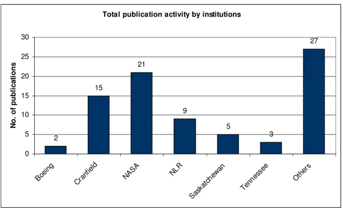
3.3.2.1 Figure 2, below, shows the total TOPM-related publication activity for each of the institutions involved in TOPM development. Histograms detailing the publication activity details over-time for the top four institutions, namely NASA, Cranfield University, the NLR and the University of Saskatchewan, follow the total publication activity histogram.
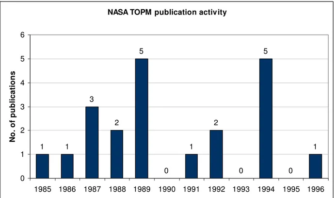
3.3.2.2 The histogram of calendar year publication activity for Cranfield University is shown in Figure 3. Figure 4 depicts a histogram of NASA’s TOPM publication activity, whereas NLR TOPM publication activity is shown in Figure 5.
TOPM, TECHNOLOGY, CERTIFICATABILITY & OPERABILITY
Total publication activity by institutions
2 15 21 9 5 3 27 0 5 10 15 20 25 30 Boei ng Cranf ield NAS A NLR Sask atch ewan Tenn ess ee Other s N o . of publ ic a ti ons
Figure 2: TOPM publication for each institution
Cranfield TOPM publication activity
1 2 3 2 1 2 1 1 2 0 1 2 3 2000 2001 2002 2003 2004 2005 2006 2007 2008 N o. of publ ic a ti ons
TOPM, TECHNOLOGY, CERTIFICATABILITY & OPERABILITY
NASA TOPM publication activity
1 1 3 2 5 0 1 2 0 5 0 1 0 1 2 3 4 5 6 1985 1986 1987 1988 1989 1990 1991 1992 1993 1994 1995 1996 N o . o f p u b lic a tio n s
Figure 4: Histogram of NASA TOPM publication activity
NLR TOPM publication activity
1 0 0 0 0 1 2 2 3 0 1 2 3 1980 1981-2 1983-4 1985-6 1987-8 1989-90 1991-2 1993-4 1995-6 N o . o f p u b lic a tio n s
Figure 5: NLR TOPM publication activity
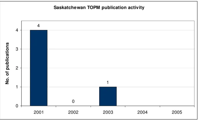
3.3.2.3 Finally, TOPM publication activity of the University of Saskatchewan is shown in the histogram of Figure 6.
TOPM, TECHNOLOGY, CERTIFICATABILITY & OPERABILITY
Saskatchewan TOPM publication activity
4 0 1 0 1 2 3 4 2001 2002 2003 2004 2005 N o . o f p u b lic a tio n s
Figure 6: The University of Saskatchewan's TOPM publication activity histogram
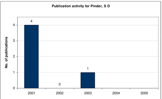
3.3.2.4 Figure 7 shows the total publication activity for the most active first-authors (against the ‘activity’ yardstick of three, or more, publications), as credited in the publications
themselves.
Total publication activity by first authors
3 4 14 3 5 3 15 35 0 5 10 15 20 25 30 35 40
Gold, T Khatwa, R Middleton, D B Milligan, M W Pinder, S D Srivatsan, R Zammit-Mangion, D Others N o. of publ ic a ti ons
TOPM, TECHNOLOGY, CERTIFICATABILITY & OPERABILITY
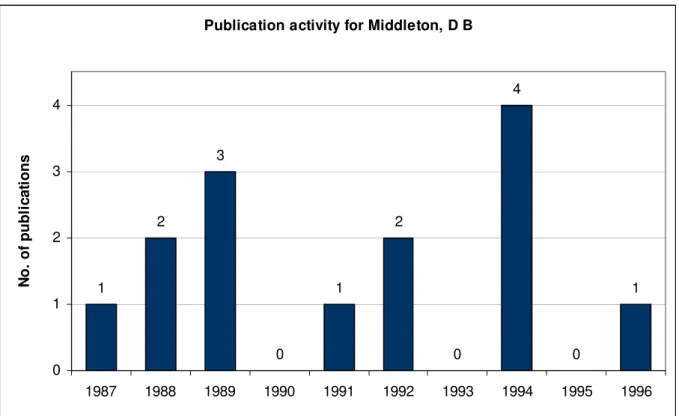
3.3.2.5 Figures 8 to 11 show TOPM-related publication activity details for the four most active first authors:
Publication activity for Zammit-Mangion, D
1 2 3 2 1 2 1 1 2 0 1 2 3 2000 2001 2002 2003 2004 2005 2006 2007 2008 N o . of publ ic a ti ons
Figure 8: Zammit-Mangion, D.'s TOPM publication activity, per calendar year. Zammit-Mangion is affiliated with Cranfield University and University of Malta and many of the above publications were co-authored with Martin Eshelby of Cranfield University.
Publication activity for Middleton, D B
1 2 3 0 1 2 0 4 0 1 0 1 2 3 4 1987 1988 1989 1990 1991 1992 1993 1994 1995 1996 N o. of publ ic a ti ons
Figure 9: Middleton, D. B.'s TOPM publication activity, per calendar year. Middleton is affiliated with NASA.
TOPM, TECHNOLOGY, CERTIFICATABILITY & OPERABILITY
Publication activity for Pinder, S D
4 0 1 0 1 2 3 4 2001 2002 2003 2004 2005 N o. of publ ic a ti ons
Figure 10: Pinder, S. D.'s TOPM publication activity, per calendar year. Pinder is affiliated with the University of Saskatchewan.
Publication activity for Khatwa, R
1 0 1 0 1 1 0 1 2 1990 1991 1992 1993 1994 1995 N o. of publ ic a ti ons
TOPM, TECHNOLOGY, CERTIFICATABILITY & OPERABILITY
3.4 Synopsis
3.4.1 A quick look at the TOPM literature survey results reveals TOPM publication activity has been going on for a little over a half-century, with the earliest publications, mostly patent applications, dating back to the mid-1950s. Since then there has been a steady level of activity until the mid-1990s when the NASA and NLR both discontinued work on their respective TOPM projects, a probable consequence of lack of industry interest.
3.4.2 With the commencement of the 21st century, TOPM publication activity has resumed, mainly regarding the work being done at Cranfield University and the University of
Saskatchewan. Majority of the work has been published by research institutions; with hardly any publications coming from airframe manufacturers, due to the proprietary nature of their work. 3.5 Latest Papers – Current Research
3.5.1 Out of the five most recent publications regarding TOPM, four are about the Cranfield TOPM technology. The latest paper, titled “Simplified Algorithm to Model Aircraft Acceleration During Takeoff”6, proposes a simplified acceleration model for real-time
performance monitoring and prediction. The proposed model is fit onto collected data to assess the goodness of fit and it is concluded that for typical aircraft, the proposed model is sufficiently accurate.
3.5.2 The second most recent publication is an overview of the design and preliminary evaluation of the Cranfield TOPM system7. The paper reviewed the requirements for a TOPM display and discussed how the Cranfield TOPM display meets the required criteria. Certification and flight deck integration issues are also detailed.
3.5.3 The third latest publication is also regarding the Cranfield TOPM. An improved takeoff acceleration performance prediction algorithm is presented which improves upon the earlier algorithm used by Cranfield TOPM8. The new algorithm results in an earlier and more accurate prediction, at the start of the takeoff run. It is concluded that with the improved accuracy and early indication capability provides high value safety information which is reliable enough to warrant integration into the flight deck.
3.5.4 At this stage of development Cranfield University sought industrial support from the Avionics OEM Sector, for the industrialisation of its TOPM. Under an NDA memorandum, Rockwell Collins at Cedar Rapids undertook an assessment of the TOPM. Whilst the outcome is unknown, Cranfield reports that no active industrialisation of the TOPM is being conducted – Cranfield also reports that it considers the research had achieved a level of maturity, such that further research was not warranted at this stage. It should be highlighted that the areas of research conducted by Cranfield addressed acceleration and integration veracity and timeliness, and TOPM display HMI integration.
4. TECHNOLOGY REVIEW
4.1 General
4.1.1 In general, a modern TOPM system consists of a means of determining operating conditions and instantaneous aircraft performance, an algorithm for predicting performance for the remainder of the takeoff run and the eventual outcome of the takeoff, and a means of
TOPM, TECHNOLOGY, CERTIFICATABILITY & OPERABILITY
displaying this information and any accompanying advisory/awareness flags to the pilot. The very first generation of TOPM development only addressed the first of these functions. However, with the advent of digital computers on-board modern aircraft, performing the remaining tasks has become possible and is the objective behind newer TOPM technology. 4.2 Summary of Latest TOPM Technology
4.2.1 Cranfield TOPM
4.2.1.1 Cranfield University’s TOPM technology is the most recent of the four major technologies developed. The Cranfield TOPM design has been driven by the need to make the TOPM system simple and reliable. The system designed at Cranfield monitors and predicts aircraft performance for only the acceleration phase of takeoff; the reason being that it is impossible to predict the post-acceleration phase performance in a reliable fashion, in the Cranfield researchers’ opinion.
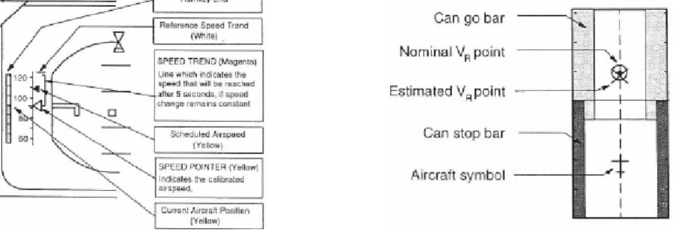
4.2.1.2 The Cranfield TOPM displays a single quantitative parameter that indicates the real-time acceleration performance relative to nominal scheduled performance. The simplistic display is used to ensure that the TOPM system is used only as a guidance aid, without increasing the pilot workload, and not as an executive device7. Reference 7 also provides a technically-useful historical summary of TOPM display technology over the decades. Figures 12 and 13,
reproduced from Ref.7, show the Canfield TOPM displays, whereas Figures 14 and 15 (from Ref.7) show the earlier NASA and NLR displays.
Figure 12: Cranfield TOPM Display, reproduced from Reference 7.
Figure 13: Cranfield TOPM Display: interpretation of the display gradations, reproduced from Reference 7.
4.2.2 A prototype of the Cranfield TOPM has been developed and evaluated in a simulator study involving airline pilots. The preliminary assessment concluded that the TOPM display has
TOPM, TECHNOLOGY, CERTIFICATABILITY & OPERABILITY
acceptable performance and flight testing should be conducted to further evaluate its acceptability in the flight deck. In relation to the present study, this would include a certificatability assessment.
Figure 14: NASA HDD TOPM display (left) and HUD TOPM display (right), reproduced from Reference 14.
Figure 15: NLR simple and more-complex TOPM displays, reproduced from Reference 13.
4.2.3 University of Saskatchewan
4.2.3.1 After Cranfield, the second most recent TOPM work has been undertaken by researchers at the University of Saskatchewan. Unlike the Cranfield TOPM, the Saskatchewan TOPM system aims to predict braking performance as well as acceleration prformance. The system uses GPS to determine the acceleration, ground speed and position of the aircraft during takeoff. This information will then be used to evaluate the aircraft’s actual takeoff performance relative to predicted nominal performance for the existing conditions. A TOPM algorithm will then compute a Situation Advisory Flag, which will be presented to the pilot to assist in the GO/NO-GO decision9. The system is designed with turbopropellor-powered transport aircraft in mind, and significantly as an after-market installation.
TOPM, TECHNOLOGY, CERTIFICATABILITY & OPERABILITY
4.2.3.2 Flight tests have been conducted to collect GPS data in order to develop the algorithm to predict the aircraft performance for the Saskatchewan TOPM system. A lumped parameter aircraft model has been developed which demonstrates the feasibility of using GPS as the sole sensor in a TOPM system. The flight test results are reproduced in Figure 16.
Figure 16: Statistical data on distance errors, using operational GPS data, compared with a DGPS system as refrence, reproduced from Pinder et al, Reference 9.
This reliability of the above-plotted data for TOPM application can be analysed in terms of AS8044. For Part 23 aeroplanes, AS8044 requires distance accuracy to be 2% (or 100 feet), and a concurrent probability of failure (which includes nuisance warnings) of 10-4 – or 3.71σ; whilst, for a Part 25 transport, 10-5 – or 4.26σ.
4.2.3.3 Consider liftoff speed for a typical Part 23 turboprop to be 50 ms-1, and ground roll distance to be 500 m. Then concurrent compliance with the AS8044 requirements for distance accuracy of +2% and nuisance warning probability of 10-4 dictates that σ = (2% x 500 m) ÷ 3.71 = 2.7 m, which from the Figure 16 plot is equivalent to approximately 90% takeoff airspeed, allowing little time for pilot recognition and response; for a Part 25 scheduled service transport, the figures is approximately 92% takeoff airspeed.
4.2.3.4 Although alerting/warning timeliness would thus appear to be possibly marginal, based upon work to date, with the widening installation of Wide Area Augmentation Systems (WAAS), the GPS distance measurement standard deviations might be reduced sufficiently, to enhance the system viability. The system concept, as an after-market installation of broad application to aircraft Types, is appealing. The system concept researchers have also addressed non-sealed (gravel) runway operations, in particular.
4.2.3.5 Future work involves design, development and testing of a prototype TOPM system and possible integration with aircraft’s onboard INS.
4.3 TOPM Technology Issues
4.3.1 The most basic issue concerning TOPM technology in general is that of reliability, not in terms of system hardware/software components and logic, but in terms of the accurate measurement of acceleration in a variety of environmental and aircraft state conditions.
TOPM, TECHNOLOGY, CERTIFICATABILITY & OPERABILITY
4.3.2 In order to improve safety of the most critical phase of flight, namely the takeoff, it is imperative that the TOPM system is able to predict aircraft performance reliably. This is because raising a false flag during takeoff ground roll would not only result in considerable economic costs, but might very well lead to an accident. Consequently, Cranfield’s TOPM system has been designed to display a quantitative measure of takeoff performance to the pilot instead of a binary flag, to limit the TOPM system to an advisory aid rather than an executive device.
4.3.3 The other major issue with TOPM technology is accuracy. Although, largely through signal processing research (notably, the digital filtering, including Kalman Filtering, of
acceleration signals, in the presence of ‘noise’ due to physical effects – such as runway surface state and atmospheric environmental state), accurate prediction of aircraft performance during acceleration phase of takeoff has been achieved with current TOPM technology, prediction of performance during braking lags in accuracy. The reason being, the inability to accurately model the runway braking friction coefficient, especially in non-dry conditions; as well as difficulties with predicting tyre and brake performance.7
4.3.4 Timeliness is another important issue of concern with TOPM systems. In order to appreciably improve takeoff safety, a reliable prediction of takeoff performance is necessary early-on in the takeoff run. Often this requirement is in conflict with the requirement to keep false alerts to a minimum (a system reliability requirement). As such, it becomes increasingly important that TOPM instrument reliability is kept in check to avoid certificatability issues. 4.3.5 Another consideration in the design of TOPM systems is its effect on pilot workload. The introduction of a TOPM should not increase the pilot workload as takeoff already has a higher crew workload compared to other phases of flight. The information displayed by a successful TOPM system should be clear and easy to interpret. Older TOPM technologies have failed to satisfy these requirements, adequately.7
5. INDUSTRY POSITION
5.1 General
5.1.1 The incorporation – installation design and certification – of TOPM systems could either be conducted at initial aeroplane build, or as an after-market modification. As such, the responsibility would be the airframe OEM or the STC holder (either as a second or third party), respectively.
5.1.2 In the past airframe OEMs have engaged upon research and development projects on TOPM systems. Reference to the literature search, Appendix A, discloses a limited number of publications from the airframe OEM Industry. Note that, in the case of Industry, only a relatively small percentage of R&D work is published; in particular, the R&D work that has been
conducted under contract, using public funds. The remainder generally remains the corporate knowledge of the Company. Thus, the relatively small amount of TOPM R&D published by Industry does not necessarily reflect the extent of TOPM research conducted by airframe OEMs.
5.2 Airbus
5.2.1 Throughout the history of Airbus, the Company has engaged in the innovative engineering design of jet transport aerodynamics and systems, including the early first civil transport with a digital electro-hydromechanical flight control system – a fly-by-wire (FBW)
TOPM, TECHNOLOGY, CERTIFICATABILITY & OPERABILITY
FCS – the A320. The fundamental design characteristics of the A320 FBW FCS have flowed throughout the subsequent Type Designs – the A330, A340 and A380.
5.2.2 Innovation has continued, not only in configuration design (the A380 being a very innovative configuration), but in systems, including those pertaining to aeroplane performance. 5.2.3 However, in the area of field performance, Airbus has invested in systems relating to landing ground roll performance, rather than takeoff roll performance. In order to put into perspective, it is worthwhile here, to record a note on landing ground roll performance. 5.2.4 Notwithstanding the number of takeoff performance accidents, landing over-runs have occurred far more frequently than takeoff over-runs, the occurrence correlating notably with contaminated runway surfaces and also adverse environmental conditions, such as windshear, wind gustiness, etc.
5.2.5 Perhaps to address landing over-run concerns, Airbus has certificated a Brake-to-Vacate system on the A380, a ‘smart’ braking system, which monitors ground roll position and distance, and essentially modulates brake calliper pressure in accordance with DTG to the pilot-selected turn-off taxiway, so as to make-good the planned exit point, without excessive,
unnecessary or over-braking (to the point of maximum braking – activating the anti-skid function – if required, on contaminated runway surfaces).
5.2.6 For the purposes of the present NRC study for Transport Canada, Airbus has been contacted. In response, Dr Andreas Reinke, Airbus Hamburg, has advised that Airbus presently has no plans to develop and certificate TOPM systems on existing or new aeroplane models or Types.
5.2.7 Although Airbus does not have any public information to release on TOPM systems development, informally the Company has indicated to the NRC that TOPM systems have been a matter of on-going consideration.
5.3 Boeing
5.3.1 Likewise, Boeing has been contacted by the NRC, in relation to discerning Boeing’s views and plans for TOPM systems. In response, Mr Robert Park of Boeing Seattle, has advised that Boeing also has no plans to develop and certificate TOPM systems on existing or new aeroplane models or Types, and would seek deep regulatory/industrial consultation and consensus, before being required to develop TOPM systems.
5.3.2 In the past, Boeing has participated in the separate NASA and NLR TOPM research projects. In addition, Boeing has conducted its own TOPM system research and development. 5.3.3 Boeing was granted US Patent 4,638,437, Aircraft performance Margin Indicator, in dated 20 January, 1987, sealed in September 1988. The patent comprehensively describes the technicalities of a TOPM indicator, which is designed for both CTOD and RTO, following engine failure at VEF, >V1 and <V1, respectively.
5.3.4 However, Boeing has not incorporated nor certificated a TOPM system in any of its certificated aeroplane Type Designs, and has no current plans to undertake any TOPM
TOPM, TECHNOLOGY, CERTIFICATABILITY & OPERABILITY
5.3.5 More recently, Boeing has a US Patent Application, US 2008/0154445 A1, dated 26 June 2008, titled Method, System and Computer Program Product for Performance Monitored Aircraft Rejected Takeoff Braking. Although this addresses elements of TOPM monitoring, namely the cases of an engine failure at VEF < V1, or of insufficient acceleration eroding the runway distance remaining to effect an RTO safely, it is more clearly aimed at preventing over-runs, in the event of a pilot decision to conduct an RTO. With reference to Figure 17, the patent application describes the runway depiction on the PFD changing, for example ‘greyed-out’, or ‘filled with a non-standard colour, such as red’, or ‘flash intermittently’. Although generic, the description of depiction-changing is possibly elucidating, insofar as it describes an information system, certainly not a commanding system.
Figure 17, Boeing generic primary flight display runway display presentations, reproduced from Boeing Patent
Application US 2008/0154445 A1, Method, System and Computer Program Product for Performance Monitored Aircraft Rejected Takeoff Braking (36, airplane symbol, 38 roll steering bar, 40 horizon line, 42 pitch bar, 44 runway symbol):- at left, normal presentation, the airplane can be stopped in the runway remaining, at right, the
depiction of the runway has changed, symbolising that the airplane can not be stopped in the runway remaining.
5.3.6 Boeing sees a multilateral approach to TOPM as being absolutely necessary, if TOPM were to be considered for regulation. In other words, Boeing requires consensus on the operational need for TOPM, and in particular clear safety benefits of TOPM installations. Boeing sees the Commercial Aviation Safety Team (CAST) forum as being a suitable for researching, discussing and reaching consensus on the technical competency and flight safety benefits of TOPM systems. Presently, the Boeing view is that neither TOPM technology is mature enough, nor, more importantly, the flight safety benefit is clear enough, for a CAST (see following section) agenda item discussion, relating to the desirability, or otherwise, of regulating for the installation of TOPM systems.
TOPM, TECHNOLOGY, CERTIFICATABILITY & OPERABILITY
5.4 Safety Bodies
5.4.1 Flight Safety Foundation
5.4.1.1 As discussed above, landing over-runs have occurred more frequently than takeoff over-runs, the occurrence correlating with contaminated runway surfaces and/or adverse
environmental conditions, such as windshear, wind gustiness, etc. For example, the Flight Safety Foundation has technical initiatives in the areas of Approach and Landing Accident reduction (of which landing over-runs are a part) and in Controlled Flight into Terrain. Figure 18 shows the substantial number of accidents, which have occurred in the Approach and Landing category.
Figure 18, approach and landing accident summary, as compiled by the Netherlands Civil Aviation Authority,
and published by the Flight Safety Foundation10, http://www.flightsafety.org/cfit4.html . 5.4.2 Commercial Aviation Safety Team
5.4.2.1 The Commercial Aviation Safety Team (CAST) is an aviation safety body, consisting of Industry, Operators and Regulators. The American Aerospace Industries Association (AIA) is a strong supporter of the CAST. CAST investigates areas of aviation safety of concern.
5.4.2.2 Since 2000, reports have been issued, chronologically in the areas of CFIT, Approach and Landing, Runway Incursions, Loss of Control, Turbulence, Wrong Runway Departures and Awareness and Energy Management in Cockpit Automation. CAST has promulgated 65 safety recommendations in these areas. However, in none of these areas is the inclusion of Takeoff Performance Monitoring, as a consideration or recommendation.
5.4.2.3 The lack of TOPM considerations is particularly interesting in the safety area of Wrong Runway Departures (WRD). The aviation safety hazard of WRD was highlighted following the takeoff over-run accident at Lexington, Kentucky of a CRJ-200, in 2006. The CAST Report11 noted the following occurrences:- 117 from FAR Part 129 operators (national, flag-carrier, scheduled), 53 from Part 135 carriers (commuter, on-demand), 7 from Part 129 carriers (international) and 440 events from Part 91 (general operating) operators.
TOPM, TECHNOLOGY, CERTIFICATABILITY & OPERABILITY
5.4.2.4 As on-board Technological Enhancements, the CAST Report11 noted seven
enhancements relating to cockpit-panel or EFB Moving Map Displays. Perhaps surprisingly, the report did not include TOPM as a possible technological enhancement. For TOPM systems which were to include full-positional awareness, a final warning of a takeoff commenced on the wrong runway could easily be detected, if such a design feature was to be included as a design feature of a TOPM system.
6. CERTIFICATION ISSUES
6.1 General – TOPM types and functionality
6.1.1.1 In the following description, Categories of TOPM system Types are described by references to the configuration of the hardware/software architecture of the system design. The possible functionality of TOPM designs is described in Levels of increasing functionality.
6.1.1.2 Certification of a TOPM system in a Transport Aeroplane could be conducted for any of the following three TOPM system design configuration-architecture Categories:-
a. a fully-integrated system (within the basic aeroplane avionics architecture), specified, installed and certificated by the airframe OEM – for this, the TOPM has become part of the Type Design, under the Type Certificate;
b. a near-fully-integrated system, specified, developed, installed and certificated by a non-airframe OEM, likely to be an avionics OEM – for this, the TOPM would be likely to be certificated as part of a Supplemental Type Certificate, for example as an element of an avionics display system, which could be retrofitted as an after-market installation;
c. an adjunct system, which has been specified, installed and certificated by a second or third-party – for this, the TOPM would often be an after-market installation, and covered by an STC; as such, it would be unlikely to be as integrated as a TOPM system in the first two categories.
6.1.1.3 Notwithstanding the TOPM Type classifications of AS80445, herein the NRC is suggesting a broadening of the TOPM classifications. In particular, the possible functionality of TOPM systems could be as deep as that depicted in the over-page diagram, and described in the suggested following table, wherefore the functionality is divided into four Levels, in pyramid fashion.
6.1.1.4 In this classification system, all Levels have performance prediction (i.e. essentially, what the distance consumed will be, when the takeoff is completed). Thus, there is no NRC Level equivalent to an AS8044 Type I (which would have no predictive capability). NRC Level IA would be less-than-equivalent to AS8044 Type II (which includes CTOD prediction), and Level IB would be equivalent to AS8044 Type III (which includes ASD and CTOD prediction).
TOPM, TECHNOLOGY, CERTIFICATABILITY & OPERABILITY
Monitors: LEVEL
& CAT
Inputs Processing, and comparison
with Aircraft Performance Model
Functionality For outcome ….
Grossly insufficient
acceleration, failure of NTOD protection IA-1: Over-run – catastrophic accident certain IA Cat c. or b.
Air data plus inertial data
Acceleration, velocity, distance and time for takeoff roll acceleration (rolling friction only)
Insufficient declared takeoff speed
IA-2: Major accident (tailstrike) likely; catastrophic accident possible As above plus:-IB Cat c. or b.
As above As above, plus deceleration extrapolation (braking friction, nominal or extrapolated) Insufficient acceleration, failure of ASD or CTOD protection
IB-1: Nil, unless engine
failure occurred near V1,
then catastrophic accident probable
Above, plus:-
Above plus:- Above plus:-
Insufficient thrust (subset of insufficient acceleration), failure of ASD or CTOD protection
IIA/B-1: Nil, unless engine failure occurred
near V1, then catastrophic
accident probable IIA /
IIB Cat b.
or a.
Engine data Thrust
Grossly insufficient thrust, failure of NTOD protection
IIA/B-2: Over-run – catastrophic accident certain
Above, plus:-
Above plus:- Above plus:-
III Cat b. or a. Position (LAT/LON) Location on airport
Wrong Runway Departure III-1: Over-run, catastrophic accident certain
Above plus:-
Above plus:- Above plus:-
IV
Cat a. Traffic
sensing
On-runway traffic
Runway Incursion IV-1: Collision, catastrophic accident certain
6.1.1.5 Initial predictive TOPM system research and development projects have been Category a. (adjunct systems), aimed at Level IB or IA, in criteria and functionality. The most recent TOPM systems research projects have been Category b. or a. systems, aimed at Level IA or IIA criteria and functionality. There are no known developments of Level III or Level IV
TOPM, TECHNOLOGY, CERTIFICATABILITY & OPERABILITY
TOPM systems, although Cranfield and Malta Universities’ TOPM researchers have undertaken Runway Incursion HMI (display and warning symbology and warnings)12.
6.1.1.6 The essential difference between Level I and Level II is the ability of a Level II TOPM to identify insufficient thrust as the reason for insufficient acceleration. The benefit of Level II would be an immediate identification of a thrust problem, such as insufficient thrust caused by a single thrust sensor failure (by cross-monitoring of all thrust-related engine parameters).
6.1.2 Level I/II A or B
6.1.2.1 The difference between the suggested ‘A’ or ‘B’ parts of Levels I or II is that Level I/II A addresses the acceleration phase of the takeoff roll, whereas Level I/II B addresses both the acceleration and deceleration (by extrapolation) phases of the takeoff, the latter in relation to protection of the ASD and CTOD. Takeoff roll acceleration addresses rolling friction, whereas protecting the ASD and CTOD addresses both rolling and braking friction, the latter by
extrapolation.
6.1.2.2 As discussed further, in contaminated runway operation, ‘solving’ the extrapolated braking friction component of ASD or CTOD protection-monitoring is technically challenging. 6.1.3 Adjunct TOPM
TOPM, TECHNOLOGY, CERTIFICATABILITY & OPERABILITY
6.1.3.1 An adjunct TOPM (category c.) would be likely to involve substantially greater certification effort than category a. or b., principally because it would need to be self-contained. Nevertheless, it would be desirable to integrate the TOPM display with a ‘glass’ PFD/ND combination. At the most basic level, an adjunct TOPM could contain its own annunciator display, but such a display would be likely to be the most compelling, and therefore difficult, to certificate.
6.1.3.2 An adjunct TOPM probably will not be conducted by the airframe OEM, but, more likely, an avionics OEM. The installation and certification processes would heavily involve display and function integration within the characteristics of an existing cockpit environment. An adjunct TOPM would be in the category of individual items of avionics equipment, such as original Ryan Stormscope, GPWS, TCAS, etc. – basically, being installed within any legacy jet transport aeroplane.
6.1.3.3 A full-function adjunct TOPM system would be complex, insofar as it would require its own inertial and air data processor, possibly its own IMU, and much hardwire interfacing with engine thrust indicating systems. An adjunct TOPM monitoring distance/acceleration alone would be less complex.
6.1.4 Near-fully-integrated TOPM
6.1.4.1 A near-fully-integrated system (category b.) would be likely to be more involved than certification of category a., because it would probably not be conducted by the airframe OEM, but, more likely, an avionics OEM, in the process involving display and function integration within the characteristics of an existing cockpit environment.
6.1.4.2 An example of a near-fully-integrated TOPM would be that incorporated within an FMS by an avionics manufacturer, and installed as part of a full, or part, ‘glass cockpit’ upgrade to legacy electromechanical, or ‘glass’, equipped transport aircraft – for example, as part of an upgrade to B747-200 or B747-300 aeroplanes.
6.1.4.3 As such, a near-fully-integrated TOPM would be likely to require, at the least, the installation of an FMS and a ‘glass’ PFD and ND, as part of the upgrade. For full TOPM
functioning, an EICAS or ECAM system would be required to be included as part of the upgrade, and the TOPM would need to interface with the EICAS/ECAM.
6.1.5 Fully-integrated TOPM
6.1.5.1 It is more likely that a fully-integrated (category a.) TOPM would ease the certification process. It would be a part of the original-build aeroplane.
6.1.5.2 An example of a fully-integrated TOPM would be a TOPM installation and
certification conducted by Airbus or Boeing, in one of their own Airplane Type Designs, at initial Type Certification.
6.1.5.3 It is likely that the TOPM would be embedded within the FMS, which by its nature, receives all air and inertial data inputs. However, in order that a TOPM fully perform all possible functions, in addition, the TOPM would need to receive a full suite of EICAS signals, which are generally not routed nor processed by the FMS. Thus, such as TOPM would involve hardware more comprehensive than contemporary flight deck standards of hardware.
TOPM, TECHNOLOGY, CERTIFICATABILITY & OPERABILITY
6.2 Certification Standards
6.2.1 For certification of a TOPM system installation, the following could form part of a possible Certification Basis:-
a. 14 CFR Part 25, 25.1309, 25.1321, 25.1353 and other clauses, applicable to the integration of the installation in the aircraft;
b. SAE AS 8044 (and referenced standards and specifications, therein) for the TOPM design;
c. RTCA DO-160D, for hardware equipment items peculiar to the TOPM; and d. RTCA DO-178C, for TOPM software.
6.3 Certification Philosophy 6.3.1 General Classification
6.3.1.1 For any of the above TOPM design configurations (i.e. categories a., b. or c.), the certification of a TOPM installation could be conducted as
a. either a command system;
b. or an information system. 6.3.2 Command System
6.3.2.1 As a command system, a TOPM would be equivalent to a Takeoff Warning System (TWS), insofar as it would be intended to annunciate a compelling command to the pilots to discontinue the takeoff.
6.3.2.2 Such as system usually annunciates a Warning in the event of a failure occurrence – as an example, the flightcrew leaving the Wing Highlift Devices inadvertently retracted. The basis of the Warning is that the aeroplane would be unable to fly at scheduled airspeeds without highlift devices appropriately deployed; in other words, an accident is certain to occur, if the takeoff was to be continued.
6.3.2.3 The types of failures that a TOPM system could possibly detect might or might not lead to the certainty of an accident, if pilot intervention action, in response to TOPM warning annunciations, was not undertaken. For example:-
a. If the TOPM included engine state inputs 9for example, from the EICAS), then it would be able to detect a failure to set sufficient thrust, and know that insufficient thrust is set, to the extent that if the insufficient thrust level was to be maintained and the takeoff continued, an over-run (catastrophic) accident is certain to occur – in this scenario (the Halifax B747 takeoff accident), a command Warning annunciation would be appropriate (the same as Highlift Device deployment failure);
b. If, using the same TOPM, an extended patch of significant runway contamination was encountered for a period on the takeoff roll (reducing acceleration), the detected failure would be: an extrapolated probability of failure to protect the acceleration-stop distance – in this scenario an accident is not certain nor probable, but possible, insofar as it requires triple concurrent failures – (i) takeoff roll runway contamination (has occurred), (ii) stop-end runway contamination (might be possible, or probable,
TOPM, TECHNOLOGY, CERTIFICATABILITY & OPERABILITY
depending upon runway topographical and environmental conditions), and (iii) engine failure at VEF close to, but less than, V1 (which is remote or possible, depending upon environmental conditions); thus, annunciation of a command Warning to discontinue the takeoff when a patch of runway contamination was encountered early in the takeoff roll might not be warranted.
6.3.2.4 With due regard to clause a., if the TOPM did not receive engine state information, it would not know of a thrust-setting failure, and could not provide the discontinue takeoff
command Warning.
6.3.3 Information System
6.3.3.1 As an information system, a TOPM would annunciate non-achievement of scheduled takeoff roll acceleration/DTG, by way of visual and/or aural information provided to the
flightcrew in the cockpit. Such information would be intended to alert or caution the flightcrew in a timely fashion, to the non-achievement of scheduled takeoff roll performance, for processing of the information and subsequent decision-making by the flightcrew, but not to command the flightcrew to a course of action. Given that the takeoff roll is an intensely time-critical phase of flight, flightcrew decision-making could only be expected to be conducted in accordance with SOPs adopted by the Operator.
6.3.4 Certification of TOPM primarily as an Information System
6.3.4.1 Notwithstanding that a fully-integrated TOPM would be capable, and therefore probably should, annunciate command Warnings in some circumstances (such as insufficient thrust, or wrong runway departure), the certification of a TOPM would probably be easier to conduct and complete if the TOPM is designed, installed and operated as an TOPM Information System (TOPMIS).
6.3.4.2 As a TOPMIS, certification of the system would critically depend upon compliance with 25.1309, in the usual manner, namely installed in the cockpit environment on the basis of ‘No Hazard No Interference (NHNI)’. Critical to such compliance would be that the TOPM does not display information which would present an unnecessary hazard to the flightcrew, in other words would not interfere with pilot decision-making during the takeoff phase of flight.
6.3.4.3 Critical to the NHNI assessment of a TOPM for certification is the timeliness and the nature of the visual and aural alerts and/or cautions provided to the pilots. Important
considerations are the integration of information (for example, onto an EFIS PFD), or the stand-alone presentation of information.
6.3.5 Example of Ancillary Flight Information Systems Certification
6.3.5.1 A TOPMIS would be an ancillary flight information system (FIS). Perhaps a useful example of the certification of ancillary FIS is the case of head-up displays (HUD). HUD FIS were used in military service for many years, before they saw civil transport aeroplane
application. When they did, possibly the earliest Type application became a quirk in the civil certification process, namely application upon the Lockheed Martin C-130J.
6.3.5.2 Prior to the C-130J, all C-130 models had been qualified for military service, using MIL STDs and SPECs. For the C-130J, Lockheed Martin pursued civil certification, against
TOPM, TECHNOLOGY, CERTIFICATABILITY & OPERABILITY
FAR 25, through the FAA. For FIS, the C-130J cockpit design included two HUD displays as the PFD.
6.3.5.3 This is a quirk, because, to the authors’ knowledge, this has been the only application of a HUD as a PFD in a civil transport aeroplane. Other than the C-130J installation design, HUD installations have been certificated as ancillary FIS. The initial installations were adjunct devices, installed under STC as after-market modifications, on the basis of enhancing flight safety. In time, HUD installations became inculcated into airframe OEM design departments – after a period of establishing and growing the market appeal of HUDs as ancillary FIS. The inculcation was spurred by the development of certification standards which enabled DH crediting to be applied to HUD installations (generally, lowering the 200 feet ILS DH by 100 feet) – in other words, the flight safety benefit had developed into an operational benefit.
7. OPERABILITY
7.1 General
7.1.1 A certificated TOPM system will provide significant safety in many areas, depending upon the design features of the TOPM – for example, covering the suggested Levels IA, IB, II, III and IV, discussed in the previous section.
7.1.2 With reference to that section, operations with a TOPM are discussed in the present section. For this, it is assumed that the TOPM has been certificated on the basis of the TOPM-determined Yellow ‘Outcomes’ of the previous section giving rise to an alert or caution
annunciation (such as a PFD-annunciated visual alert or caution) and the Red ‘Outcomes’ giving rise to a Warning annunciation (such as a PFD-annunciated visual warning and an aural
Warning).
7.2 Normal Operations
7.2.1 A Level IA or IB TOPM, used in all normal operations, would need to detect insufficient acceleration at a relatively early stage of the takeoff roll, in order to be usefully applied. It is perhaps clear-cut that a reasonable SOP-directed pilot response to a TOPM
Warning annunciation could be expected to be rejecting the takeoff. However, the SOP-directed pilot response to a TOPM alert or caution is less clear-cut. The surety of the pilot response (decision-making) would be the TOPM ‘ruggedness’ to a wide-range of takeoff parametric variations, which would probably be reflected in a wide certification flight test matrix for verification and validation.
7.2.2 Such parameters would include:-
a. Runway slope (in particular, localised runway up-slopes) – note that a Level III TOPM (which would include accurate LAT and LONG sensing, and surface height AMSL, from an embedded terrain database) would have the capability to account for localised runway upslopes);
b. Runway surface condition, including the acceleration-perturbing effects of runway texture pattern, in the case of concrete runway surfaces;
c. A range of tyre inflation pressures, covering despatch minimum and maximum; d. Dragging brake;
TOPM, TECHNOLOGY, CERTIFICATABILITY & OPERABILITY
e. Mis-set thrust, or thrust sensor failure.
7.2.3 Notwithstanding the above, it should be expected that a TOPM should annunciate alerts and warnings correctly (for example, for a mis-entered takeoff weight or takeoff speeds), in the conditions of a level asphalt runway surface in benign atmospheric conditions.
7.3 Wind Gustiness
7.3.1 The variability of a gusty wind, particularly a gusting crosswind, or a topographically or environmentally-induced windshear (for example, a localised tailwind over the initial
acceleration segment of the runway), would be likely to be a difficult operational environment for determination of a TOPM solution.
7.4 Different Runway Surfaces
7.4.1 Neither contemporary, nor earlier FAA or EASA airworthiness regulations or requirements require the scheduling of normal takeoff distances for a variety of
non-contaminated runway surfaces. However, a commuter aircraft approved for unsealed runway (grass or gravel) operations would encounter higher rolling friction, μR during the takeoff ground roll.
7.4.2 In the past, some national Authorities have required scheduling for such non-contaminated runway surface μR differences (not variability). For example, the Australian Department of Transport required all Normal Category aeroplanes to have scheduled in their Flight Manuals, normal takeoff distances for
a. Hard, dry runways, b. Short grass runways,
c. Long, dry grass runways, and d. Long, wet grass runways.
7.4.3 For such scheduling, various μR values, of increasing magnitude respectively, were applied throughout the takeoff acceleration ground roll. Without such a scheduled variation, a TOPM would not have an embedded performance model, for comparison of the sensed motion. Even with an embedded model, unsealed grass or gravel runways have greater local variability in surface condition (and hence, μR) than sealed runway surfaces.
7.5 Contaminated Runway Operations 7.5.1 General
7.5.1.1 Contaminated runway operations potentially pose substantial difficulties for the determination of a TOPM solution, due to runway rolling and braking friction considerations alone. The usage of the NRC Falcon on contaminated runway friction measurements was instrumental to Transport Canada, in the establishment of the CRFI. Nevertheless the work disclosed significant variations in derived rolling and braking friction. Operationally CRFI is used to address increased landing distance and lateral controllability (by limiting the maximum crosswind, in inverse proportion to the value of CRFI, determined by a mu-meter wheel), and to relate CRFI to contamination type.
TOPM, TECHNOLOGY, CERTIFICATABILITY & OPERABILITY
7.5.1.2 The scatter in rolling and braking friction data quite probably would occur in any flight test data-set. Large variations were apparent in the runway friction trials at Cranfield, UK. Indeed, JAR-OPS, under UK application (changeover effected 1998/99, completed by 2000), excluded contaminated runway operations, at least until 2002, defined as any ice, or standing water/precipitation of depth greater than 3 mm.
7.5.1.3 Whilst such an operational exclusion would not be economically tolerable in the North American environment, it remains for the foreseeable future, the case that ASD and CTOD on contaminated runway surfaces can not be scheduled in a regulatory manner. Rather, airframe OEMs schedule recommended takeoff and landing distances in contaminated runway conditions. 7.5.2 Runway contaminants – effect upon μR and μB
7.5.3 Likewise, the effective operation of TOPM on contaminated runway surfaces might possibly be very difficult to achieve, because of the wide variability in contaminated runway rolling and braking friction; consider a number of cases:-
a. Fresh snow – increases rolling friction, but reduces braking friction, so that TOPM
might be effective in extrapolating a sensed loss of acceleration on the takeoff roll, to a loss of braking – thus, a sensed failure of ASD protection might be effectively predicted by a TOPM, in this case; however, if the fresh snow was very thick (unploughed), a TOPM might correctly predict failure of NTOD availability;
b. Compact snow – well-compacted snow can be expected to have only a small,
possibly negligible, effect upon takeoff roll acceleration, but a substantial loss in braking friction – thus, a TOPM would be unlikely to sense a failure of ASD protection, in this case;
c. Ice, freezing rain etc – might very-well reduce rolling friction, but would be expected
to reduce braking friction to a very low value – thus, as above, TOPM would be unlikely to sense a failure in ASD protection.
7.5.4 Technical Solution Possibilities
7.5.4.1 To summarise, contaminated runway surface operations pose substantial difficulties for the conceived useful operation of a TOPM. At the least, for cases b. and c., above, an ancillary advice to the TOPM would be required, such as a manual entry of measured CRFI. To re-iterate, however, CRFI presently is used for landing distance effects and for lateral control, not for takeoff distance or CTOD performance aid – perhaps, it might require further development to be applied in the latter category. AS8044 allows for the insertion of μB-related parameters, for the prediction of CTOD and stop distances.
7.5.4.2 Another method of operations could be the usage of a measuring device on the aircraft. To the knowledge of the NRC, no such system is presently available. One possible measurement device could be a ‘dolly’ dragging wheel, articulated off a main landing gear leg (MLG) or bogie. It would probably be substantially smaller in diameter than a CRFI or James wheel, which would require development, to ascertain accurate μ measurements (the accuracy would be likely to decrease with a reduction in the ratio of wheel diameter to contaminant depth). Furthermore, the device would need to be a ‘smart’ system, with a means for holding constant downforce on the braked-wheel, in the presence of tyre deflection, in reaction to variable
suspension loads, from shock strut operation during the takeoff roll on uneven runways surfaces, or in the presence of other loading variability, such as wind gusts.