Artificial Gravity: Evaluation of adaptation to head movements during short-radius centrifugation using subjective measures.
By
Lisette Emma Lyne
MSci Physics with Astrophysics (1997) The University of Birmingham, United Kingdom
Submitted to the Department of Aeronautics and Astronautics in Partial Fulfillment of the Requirements for the Degree of
Master of Science in Aeronautics and Astronautics at the
Massachusetts Institute of Technology June '2000
@ 2000 Massachusetts Institute of Technology All rights reserved
Signature of Author.. ...
Depart ent Aeronautics and Astronautics May 12, 2000
C ertified by ... ... ...
Professor Laurence Young Apollo Professor of Astronautics, Department of Aeronautics and Astronautics
Accepted by...
MASSA CHUSETTS INSTITUTE OF TECHNOLOGY
.... ... ... ... ... , I...
Professor Nesbitt Hagood Chair, Graduate Office
Artificial Gravity: Evaluation of adaptation to head movements during short-radius centrifugation using subjective measures.
By
Lisette Emma Lyne
Submitted to the Department of Aeronautics and Astronautics on May 12, 2000 in partial fulfillment of the
requirements for the Degree of
Master of Science in Aeronautics and Astronautics
ABSTRACT
An experiment was performed to determine the ability of humans to adapt, and retain adaptation to out-of-plane head movements made during short-radius centrifugation. The hypothesis for the experiment was as follows: Repeated exposure to a series of yaw head movements made during short-radius centrifugation at 23rpm, (with the subject lying supine and the head on the axis of rotation) will result in a decrease in the magnitude of inappropriate perceived self-motion sensations and severity of motion sickness.
Verbal accounts of perceived pitch, motion-sickness scores and computer animations of subjective sensations were obtained from eight subjects, during three sessions performed at the following intervals: day one, day two and day eight. Verbal accounts of perceived pitch obtained during rotation and post-experiment motion-sickness scores provide clear evidence of adaptation to the stimulus between days one and two, and some retention of adaptation to day eight. Computer animations of subjective sensations obtained after the experiment and motion-sickness scores reported during the experiment do not provide conclusive evidence of adaptation, or retention of adaptation. The validity of these techniques were explored, along with a qualitative analysis of the results.
Thesis Supervisor: Laurence Young
Title: Apollo Professor of Astronautics, Dept. of Aeronautics and Astronautics
This work was supported by the National Space Biomedical Research Institute through a cooperative agreement with the National Aeronautics and Space Administration
ACKNOWLEDGEMENTS
I would like to thank the following individuals and groups for their assistance during the making of my thesis:
Professor Young for converting me from Astrophysics to Bioengineering, and supervising this research. Your help and support over the past 2 years has been greatly appreciated. Dr Heiko Hecht for all your help and support with the project over the past year. Thanks for answering all my questions and giving valuable advice.
Kathleen Sienko for putting up with me as your lab partner, roommate, office partner and fellow Star Market shopper. I shall always remember the fun we had wiring the centrifuge in the spring. Here's to another exciting summer on opposite sides of the globe, but with less Thai whisky and Russian vodka this time!!
Carol Cheung for being the world's only dancing PID feedback control system engineer. Thanks for all your hard work and contributions to the project.
Jessica Kavelaars for bringing medical expertise to the project.
Dr Alan Natapoff for all those words of wisdom and help with statistical analysis.
Marsha Warren for many enlightening conversations and for making the fleece eye cover. Dick Perdichizzi for assisting us with automating the centrifuge.
Jeffery Munson for being a human guinea pig. Thanks for letting us perform all those pilot experiments on you.
Don Parker for technical assistance with Worldup and allowing me to use your computer models.
The National Space Biomedical research Institute for funding the research.
The Rotary club of Rushden, who provided me with funding, and the opportunity to study in America as part of a cultural exchange program. Thank you for believing in me and giving me this amazing experience.
The Fulbright Commission, who provided me with funding during my first year in America.
TABLE OF CONTENTS
1. INTRODUCTION ...
9
2. BACKGROUND...
11
2.1 CURRENT COUNTERMEASURES... 11
2.2 PHYSICS OF ROTATING ENVIRONMENTS ... 13
2.2.1 Centrifugal force ... 14
2.2.2 C oriolis force ... 19
2.2.3 G ravity gradients ... 22
2.2.4 Effect of making head turns in a rotating environment on the sem icircular canals ... 22
2.3 M OTION SICKNESS... 38
3. METHODS... 38
3.1 D E SIG N ... 3 8 3.2 E Q UIPM ENT ... 40
3.2.1 MIT short-radius centrifuge ... 40
3.2.2 Subjective measurement tools ... 42
3.3 SUBJECTS ... 45
3.4 EXPERIMENTAL PROCEDURE ... 45
3.4.1 Training, instrumentation and pre-experiment data collection ... 46
3.4.2 D ata collection ... 47
3.4.3 Post-experiment data collection... 51
4. RESULTS... 51
4.1 PENSACOLA MOTION-SICKNESS SURVEY ... 51
4.2 POST-EXPERIMENT MOTION-SICKNESS SCORES ... 53
4.3 V ERBAL R EPORTS... 55
4.3.1 Magnitude and direction of pitch sensation... 57
5. COMPARISONS...58
5.1 COMPARISON OF THE PENSACOLA MOTION SICKNESS SCORES TO THE TIME TAKEN TO RETURN TO A POST MOTION SICKNESS SCORE OF ZERO... 58
5.2 COMPARISON OF THE PENSACOLA MOTION SICKNESS SCORE TO THE 0-20 SCA LE ... . ... 59
5.3 COMPARISON OF MOTION SICKNESS AND SUBJECTIVE SENSATION RETENTION 60
6. DISCUSSIONS AND RECOMMENDATIONS...61
6.1 RETENTION OF ADAPTATION ... 61
6.2 HABITUATION USING VISUAL TASKS... 63
6.3 TRANSFER OF ADAPTATION ... 63
7. ADDITIONAL RESULTS AND DISCUSSION PART ONE...66
7.1 W ORLDUP COMPUTER ANIMATION ... 66
7.2 VALIDITY OF W ORLDUP RESULTS... 69
7.3 EVALUATION OF WORLDUP AS A TOOL FOR CAPTURING SUBJECTIVE SENSATIONS... 70
7.4 RECOMMENDATIONS ... 71
8. ADDITIONAL RESULTS AND DISCUSSION PART TWO...72
8.1 MOTION SICKNESS SCORES REPORTED DURING THE EXPERIMENT... 72
8.2 QUALITATIVE EVALUATION OF PEAK MOTION-SICKNESS SCORES AND NUMBER OF HEAD TURNS ... 75
8.3 TIME TO REACH PEAK MOTION SICKNESS ... 77
9. CO N CLU SIO N ...
78
BIBLIOGRAPHY ... 80
APPENDIX A -PENSACOLA DIAGNOSTIC INDEX METHOD FOR SCORING MOTION-SICKNESS SYMPTOMS... 83
APPENDIX B -HUMAN INTERFACE TECHNOLOGY LABORATORY TECHNICAL REPORT ... ... 87
APPENDIX C - MEDICAL QUESTIONNAIRE ... 90
APPENDIX D -MEDICAL DISQUALIFYING CONDITIONS ... 91
APPENDIX E -DATA COLLECTION AND SUBJECT BRIEFING SHEETS.... 92
APPENDIX F - CONSENT FORM ... 100
APPENDIX G - PENSACOLA MOTION-SICKNESS SCORES ... 103
APPENDIX H - POST EXPERIMENT MOTION-SICKNESS SCORES ... 104
APPENDIX I - VERBAL REPORTS... 105
APPENDIX J - MATLAB CODE FOR WORLDUP ANALYSIS...108
APPENDIX K - WORLDUP PITCH AND YAW PLOTS ... 109
APPENDIX L - WORLDUP RESULTS ... 117 APPENDIX M - MOTION-SICKNESS SCORES REPORTED DURING THE
TABLE OF FIGURES
FIGURE 1-FORCES ACTING ON THE SUBJECT'S FEET ON THE ROTATING SHORT-RADIUS
CENTRIFUGE, AS VIEWED FROM THE STATIONARY FRAME OF REFERENCE... 14
FIGURE 2-FORCES ACTING ON THE SUBJECT'S FEET ON THE ROTATING SHORT-RADIUS
CENTRIFUGE, AS VIEWED FROM THE ROTATING FRAME OF REFERENCE... 15
FIGURE 3-A RECTANGULAR BLOCK DIVIDED INTO SECTIONS OF LENGTH 8R, WIDTH W AND D EPTH D ... 17 FIGURE 4-ANGULAR VELOCITY REQUIRED FOR A TOTAL CENTRIFUGAL FORCE EQUAL TO
EARTHS GRAVITY, FOR SUBJECTS OR VARYING HEIGHT WITH THE CENTER OF ROTATION AT THE HEAD. ... 19 FIGURE 5-DIRECTION OF THE CORIOLIS FORCE FOR VARIOUS HAND MOVEMENTS ON A
SHORT-RADIUS CENTRIFUGE, ROTATING CLOCKWISE. ... 21 FIGURE 6-THE VESTIBULAR SYSTEM ... 23 FIGURE 7 - PLANES OF THE SEMICIRCULAR CANALS WITH RESPECT TO THE HEAD. X,Y AND Z ARE THE PRINCIPLE AXES OF THE HEAD. L, AV AND PV REFER RESPECTIVELY TO THE LATERAL (HORIZONTAL), ANTERIOR VERTICAL AND POSTERIOR CANALS... 24 FIGURE 8 - A CUT-AWAY VIEW OF THE AMPULLA OF A SEMICIRCULAR CANAL TO SHOW THE SENSORY CELLS AND CUPULA. ... 25 FIGURE 9 - CUPULA DEFLECTION BY AN ANGULAR ACCELERATION IN THE PLANE OF THE
SEMICIRCULAR CANAL. THE RING OF ENDOLYMPH RESISTS ANGULAR ACCELERATION BECAUSE OF ITS INERTIA, AND A FORCE IS EXERTED ON THE CUPULA WHICH CAUSES IT TO BE DEFLECTED .... . -. 26
FIGURE 10 - ORTHOGONAL COORDINATE AXES IN THE ROTATING AND STATIONARY FRAMES OF REFERENCE ... ... . ... 29
FIGURE 11 - POSITION OF THE SEMICIRCULAR CANALS DURING A 90-DEGREE YAW HEAD
TURN FROM (A) RED TO (B) NU, ON A CLOCKWISE ROTATING PLATFORM. ... 32
FIGURE 12 - MODIFIED YOUNG-OMAN LAPLACE TRANSFER FUNCTION MODEL FOR THE CANAL RESPONSE TO ROTATION... ... 34
FIGURE 13 -RESPONSE OF THE CUPULA (BLACK) TO A VELOCITY CHANGE OF 23PRMS... 35
(2.4 RADIANS/SEC) IN ONE SECOND IN THE PITCH CANAL (DOTTED GREY), USING A
MODIFIED YOUNG-OMAN LAPLACE TRANSFER FUNCTION MODEL ... 35
FIGURE 14 - RESPONSE OF THE CUPULA (BLACK) TO A VELOCITY CHANGE OF 23PRMS... 36
(2.4 RADIANS/SEC) IN ONE SECOND IN THE ROLL CANAL (DOTTED GREY), USING A MODIFIED YOUNG-OMAN LAPLACE TRANSFER FUNCTION MODEL. ... 36
FIGURE 15 -RESPONSE OF THE CUPULA (BLACK) IN THE YAW CANAL TO A 90 DEGREE YAW
HEAD TURN (DOTTED GREY) ON A 23PRM ROTATING DEVICE, USING A MODIFIED YOUNG-OMAN LAPLACE TRANSFER FUNCTION MODEL. ... 37 FIGURE 16-THE MIT SHORT-RADIUS CENTRIFUGE ... 41
FIGURE 17-SCHEMATIC OF THE MIT SHORT-RADIUS CENTRIFUGE ... 42
FIGURE 18-ELEVEN PHASES OF THE MAIN EXPERIMENT, INCLUDING CENTRIFUGE ROTATION STATUS, LIGHTING CONDITIONS, HEAD POSITION, LOCATION OF MOTION-SICKNESS SCORES AND LOCATION OF VERBAL REPORTS... 48 FIGURE 19-PENSACOLA MOTION-SICKNESS SCORE BY DAY. ... 52
FIGURE 20-NUMBER OF SUBJECTS (N=8) WHO EXPERIENCED THE MOTION-SICKNESS
SYMPTOM LISTED, AT SOME POINT DURING THE THREE TEST DAYS... 53
FIGURE 21-TIME (MINUTES) TO RETURN TO A MOTION-SICKNESS SCORE OF ZERO BY DAY, FOR EIGHT SUBJECTS... 54
FIGURE 22-Box PLOT OF THE REPORTED PERCEIVED PITCH SENSATION EXPERIENCED DURING PRE- AND POST-ADAPTATION RED TO HU HEAD TURNS, FOR SIX SUBJECTS. ONE SUBJECT WHO EXPERIENCED A TUMBLING SENSATION HAS BEEN OMITTED FROM THE PLOT FOR SCALING PURPOSES. ... ... 56
FIGURE 23-Box PLOT OF THE REPORTED PERCEIVED PITCH SENSATION EXPERIENCED DURING PRE- AND POST-ADAPTATION HU TO RED HEAD TURNS, FOR SIX SUBJECTS. ONE SUBJECT WHO EXPERIENCED A TUMBLING SENSATION HAS BEEN OMITTED FROM THE PLOT FOR SCALING PURPOSES. ... 56
FIGURE 24-PERCEIVED PITCH DIRECTION WHEN TURNING FROM RED TO NU AND NU TO R E D .... ... 57
FIGURE 25-SCATTER PLOT OF PENSACOLA MOTION-SICKNESS SCORES AGAINST THE 0-20 SCALE MOTION SICKNESS SCORE REPORTED AFTER CENTRIFUGATION, FOR EIGHT SUBJECTS ON THREE TEST DAYS... ... 60
FIGURE 26-PEAK PITCH MAGNITUDES IN DEGREES BY DAY FOR EIGHT SUBJECTS. PITCH MAGNITUDES WERE COLLECTED USING WORLDUP, A COMPUTER ANIMATION SOFTWARE PACKAGE...---... .. .... 67
FIGURE 27-WoRLDUP ACCURACY SCORES BY DAY FOR EIGHT SUBJECTS ... 68
FIGURE 28-WORLDUP DIFFICULTY SCORES BY DAY FOR EIGHT SUBJECTS... 69
FIGURE 29-PEAK MOTION-SICKNESS SCORES (0-20) FOR EIGHT SUBJECTS, BY DAY. ... 72
FIGURE 30-TOTAL NUMBER OF HEAD MOVEMENTS MADE DURING LIGHT ADAPTATION FOR EIGHT SUBJECTS BY DAY, THE AVERAGE NUMBER OF HEAD MOVEMENTS FOR ALL SUBJECTS PER DAY AND THE STANDARD DEVIATION. ... 73
FIGURE 31-TIME TO REACH A PEAK MOTION SICKNESS SCORE (SECONDS) FOR SEVEN SUBJECTS, BY DAY... 74
FIGURE 32-DISTRIBUTION OF NUMBER OF CASES WITH PHASE OF EXPERIMENT, DURING WHICH PEAK MOTION-SICKNESS SYMPTOMS OCCURRED... 75
Humanity will not remain on the Earth forever, but in the pursuit of light and space will at first timidly penetrate beyond the limits of the atmosphere, and then will conquer all the space around the Sun.
1.
Introduction
Human exposure to long duration weightlessness results in a variety of debilitating effects including cardiovascular de-conditioning, bone loss, and muscle atrophy. Current countermeasures include the penguin suit, fluid loading, diet modification, lower body negative pressure, preflight adaptation training and in-flight exercise. Current countermeasures have proven somewhat successful in a number of areas, however, no countermeasure or combination of countermeasures have been able to preserve bone density. The limited success of current countermeasures has led scientists to consider artificial gravity as a possible solution. Short-term flights and space station missions are unlikely to warrant such an extreme countermeasure, as medical expertise is available on return to Earth. However, for long duration explorations such as a mission to Mars, medical support would not be available on arrival. Provision of artificial gravity during a trip to Mars may enable astronauts to maintain the ability to perform emergency extravehicular activities and avoid bone fractures when exposed to the gravity of Mars.
Provision of artificial gravity can take the form of a large rotating structure or a short-radius centrifuge. Large rotating structures like Von Braun's 125-foot torus spinning at 3rpm would provide continuous artificial gravity with minimal undesirable physiological effects (Young, 1999). Such structures are a complex engineering challenge, and extremely expensive. Short-radius centrifugation would provide intermittent gravity exposure, but would be significantly cheaper and less complex. However, short-radius centrifugation requires large angular velocities to obtain a force of IG, this results in postural and vestibular disturbances. This report considers short-radius centrifugation rather than large rotating structures as the mechanism to provide artificial gravity.
Vestibular disturbances occur when the head is rotated about an axis which is itself on a device that is rotating about another axis. Out-of-Plane head movements made during short-radius centrifugation, results in stimulation of semicircular canal in planes not
non-compensatory nystagmus, inappropriate perceived self-motion and in some cases motion sickness. In order for short-radius centrifugation to be considered as a viable alternative to current countermeasures, it is essential that astronauts are able to develop and retain adaptation to inappropriate eye reflexes and perceived sensations of self-motion, resulting from head turns during centrifugation. The ability to simultaneously retain two sensory programs, for rotating and non-rotating environments, would enable the astronaut to maintain appropriate spatial orientation and experience low motion sickness levels for active head movements in two different gravity environments. If this is proven not to be the case, a period of disorientation and motion sickness might occur each time the astronaut transitions to and from the short-radius centrifuge. Restricting head movements to avoid such conflicting stimuli is not desirable, as it would be extremely uncomfortable for long and repeated exposures and possibly inconsistent with the need for active exercise on the rotator.
Adaptation is defined as the development of an appropriate new response to a novel environment. This is different from habituation, which results in a reduced response to the conflicting sensory environment upon repeated exposure (Tang and Vidulich, forthcoming late 2000). Dual adaptation is the ability to adapt to a sensory rearrangement more rapidly and/or more completely after repeated experienced with it. Dual adaptation has been found to occur when subjects alternate repeatedly between adapting to the sensory rearrangement and readapting to the normal environment. This repeated alternating exposure fosters the development of a separate adaptation to each situation (Welch, Bridgeman and Williams, 1998). In Welch's experiment, subjects actively made head movements during alternating exposure to a visual-vestibular rearrangement (target/head gain = 0.5) and the normal situation (target/head gain = 0.0). These conditions produced adaptation and dual adaptation of the vestibulo-ocular reflex.
Another study by Welch, Anand and Browman (1993) involved subjects alternating between adapting their visuomotor coordination to a 30-diopter prismatic displacement and readapting to normal vision. In this experiment, dual adaptation was observed by the
end of ten alternating cycles. The same paper describes how dual adaptation can be found in everyday situations. For example, after repeatedly donning and removing spectacles, wearers often report disappearance of depth distortions, illusory visual motion and coordination difficulties they had experienced earlier.
In our study, it is hypothesized that with repeated exposure to yaw head movements during short-radius centrifugation at 23rpm (with the subject lying supine and the head on the axis of rotation), adaptation and development of dual adaptation to head movements in the rotating environment will occur. The measures of adaptation were non-compensatory vertical nystagmus, inappropriate perceived self-motion sensations and motion sickness. Evidence exists from current literature to support our hypothesis. Guedry, (1965) found evidence for habituation to vestibular stimulation and retention of adaptation from rotation. Nystagmus and subjective effects were found to decrease after twelve days of rotation, and responses were suppressed compared with initial levels two days and three weeks after rotation. Retention of adaptation to motion sickness has also been found by Senqi and Stem, (1999). That study found that adaptation to motion sickness eliciting stimulation of optokinetic rotation is almost completely retained for one month and partially retained for one year.
2.
Background
2.1 Current Countermeasures
The following section provides an outline of the effects of micro-gravity on skeletal muscles, bones and the cardiovascular system. Each section describes the current countermeasures used, and outlines the success or limitations of current techniques. Where applicable, a justification for artificial gravity is given, and the potential benefits described. Further information on this topic can be found from the NASA task force on countermeasures final report, May 1997.
The musculoskeletal system has evolved over millions of years and adapted to the gravity environment of Earth. In microgravity, muscles need no longer perform work against Earth's gravity. Exposure to this state of unloading results in atrophy of primarily slow-twitch muscles (fast-slow-twitch muscles also experience atrophy, but are affected less than slow-twitch muscles), and a reduction in muscle force and power generating properties. Astronauts exposed to prolonged space flight exhibit reduced strength, power and musculoskeletal endurance. Such deficits will undoubtedly impair the astronaut's ability to perform strenuous extravehicular activity and the ability to perform high intensity egress activities. Countermeasures currently used to maintain the skeletal muscle system involve exercise, using treadmills, rowing devices and cycle ergometers. Exercise programs using the devices mentioned above enhance endurance but fail to provide large resistance forces. Ground based experiments have shown that heavy resistance exercises are the most effective at preventing muscle atrophy and loss of muscle strength. Evidence from both the American and Russian space programs indicate that the exercise programs and other countermeasures have been marginally successful in slowing muscle structure and function deficits. Provision of artificial gravity combined with exercise (for example, a human powered short arm centrifuge), would enable astronauts to exercise in a gravity environment, providing both endurance and heavy resistance training.
In the absence of gravitational stresses, bones start releasing calcium salts, the mineral responsible for bone strength. The lost of calcium is measured by testing for increased calcium in urine and post-flight bone density tests. Calcium loss begins slowly in the first week and increases gradually over the next several months. The average whole body loss rate is 0.5% per month, with peak loss rates of 3-5% per month in weight-bearing bones (Churchill, 1997). Unlike other physiologic adaptations, calcium loss did not reach a plateau during the 84 day Skylab mission. Reduction in bone calcium results in
decreased bone and muscle strength. This reduction in strength is likely to increase the chance of bone fractures in the event of a fall. Another concern is the rapid increase in urinary calcium, which may increase the risk of kidney stone formation. The mechanism by which bone calcium is lost in microgravity is poorly understood. Current
countermeasures include primarily exercise and some dietary measures. Current Mir exercise programs have been unsuccessful in inhibiting flight related bone loss, and nutritional requirements have not been established. Provision of artificial gravity could potentially reduce or eliminate bone loss during spaceflight. However, little is known about the level or duration of artificial gravity required to prevent bone loss.
In spaceflight, blood which is normally pulled to the legs due to gravity moves to the area of least resistance, the venous vessels in the chest. The body interprets this to mean that the body is overfilled and adjusts the mechanical determinants of arterial pressure. The kidneys also excrete extra fluid in the form of urine. Problems occur when astronauts return to a gravity environment, the gravitational pull results in blood pooling from the chest to the legs. The effective circulating volume is considerably smaller, resulting in dizziness or even fainting. This phenomenon is called orthostatic intolerance and is due to the inability to maintain blood pressure. Orthostatic intolerance may seriously affect an astronaut's ability to egress the space vehicle following reentry in the case of an emergency landing. Current countermeasures used to protect orthostatic tolerance include, consuming salt tablets before reentry to restore plasma and blood volume, wearing anti-g suits during reentry to prevent blood from pooling to the legs and in-flight exposure to lower body negative pressure. Provision of artificial gravity in space would replace the physiological stimuli to the cardiovascular system and simultaneously protect
aerobic capacity if exercise was performed on the centrifuge. 2.2 Physics of rotating environments
The centrifugal force is an inertial force, which appears if the motion of a particle is analyzed from the standpoint of a rotating reference frame. Centrifugal force is the artificial equivalent (artificial gravity) to the gravitational force on Earth. There are four major features that cause artificial gravity to be different from real gravity. These features fall into two categories, static and dynamic features. Static features include the
between the two categories lies with the state of the person or object relative to the artificial gravity environment. Forces acting on a human in a large rotating structure have been well documented (Stone, 1970). The following discussion will focus on the forces generated in the particular case of a short-radius centrifuge. The following section discusses the centrifugal force, Coriolis force, gravity gradients and the effect of making head turns in a rotating environment on the semicircular canals (this discussion includes cross-coupled angular accelerations).
2.2.1 Centrifugal force
The centrifugal force is an inertial force that always appears if the motion of a particle is described and analyzed from the standpoint of a rotating reference frame. In order to fully understand the centrifugal force, analysis of the forces acting on a subject on the rotating centrifuge will take place both in the stationary and rotating frames of reference.
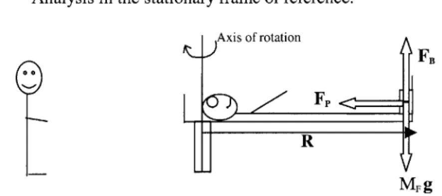
(a) Analysis in the stationary frame of reference. Axis of rotation
FB
R
MF g
FIGURE 1-FORCES ACTING ON THE SUBJECT'S FEET ON THE ROTATING SHORT-RADIUS CENTRIFUGE, AS VIEWED FROM THE STATIONARY FRAME OF REFERENCE.
Figure 1 shows a subject rotating at constant velocity, on a short-radius centrifuge. The axis of rotation is at the top of the subject's head. The key parameters are defined as follows; o = Angular velocity, R = Radius of Rotation (also equal to the height of the subject), F, = Reaction force of foot-plate on the subject's feet, MF g = Force due to gravity acting on the subject's feet, where MF represents the mass of the subject's feet, and FB = Reaction force of centrifuge on subject's feet. Forces (different magnitudes) act
at all points along the subject's body, however for simplicity the following discussion will focus only on the forces acting at the subject's feet. The force diagram in Figure 1 represents the ideal situation where the subject is levitated on the centrifuge, and hence the reaction force is provided solely by the footplate. In reality the person remains at rest due to both the reaction force of the footplate and the frictional force due to the subject lying on the centrifuge.
From the standpoint of the stationary (inertial) frame of reference, the feet have an acceleration ((&R), towards the axis of rotation. The force that causes this acceleration on the feet is MFWR. The feet are also being pushed radially by the inertial force from the rest of the body (neglecting the frictional force between the body and the centrifuge), given by (MB-MF)r'w2, where MB is the body mass and r' is the distance from the axis of rotation to the position of the center of mass of the body minus the mass of the feet. The net force FR causing the acceleration towards the axis of rotation is supplied by the
reaction force of the footplate on the feet. Therefore
FR= MF Rw + (MB-MF)r'(
(b) Analysis in the rotating frame of reference.
Axis of rotation
FB
FFp
. FCFR
Figure 2 shows the forces acting on the subject's feet from the standpoint of the frame of reference that rotates with the centrifuge, i.e. the subject's perspective. The acceleration of the subject's feet as viewed by the subject is zero. In order to maintain the validity of Newton's law in the rotating frame of reference, in addition to FR, the feet experience an inertial force FCF which is equal and opposite to FR, and hence directed radially outwards. In the rotating frame of reference, the net horizontal force is given by equation 2
FCF + FR 0 (2)
Hence,
FCF - MF &R+(MB-MF)r'&
(3)
where FCF is the centrifugal force. It is this force which acts radially outwards from the
feet that is referred to as artificial gravity. If all the body except the feet were restrained by friction and the feet had no frictional force, only the first term in equation 3 would
apply.
The centrifugal force does not act solely at the subject's feet, but along the entire body. However, because the centrifugal force is proportional to the radius of rotation, the centrifugal force decreases in value along the body, until the force is zero at the head. Due to the Earth's gravity vector, the net force experienced will be the resultant of the centrifugal force and weight. In space the gravity component of Earth will be absent and only the centrifugal force will be present.
The centrifugal force creates a gravity gradient along the subject's body. By approximating the human body to a rectangle of suitable dimensions, and approximating the body density to that of water (since humans consist of 90% water), the total net centrifugal force has been calculated by integrating along the body. The various steps in
the calculation are outlined below, in addition to a comparison with the net gravitation force exerted by the gravitational pull of Earth.
(a) Consider the body to be a rectangle with the following
or
R
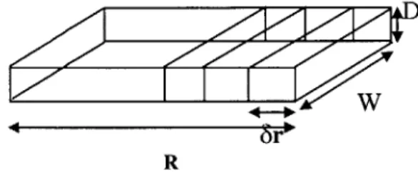
FIGURE 3-A RECTANGULAR BLOCK DIVIDED INTO SECTIONS OF LENGTH 8R, WIDTH W AND
DEPTH D.
(b) If the body is divided into sections of length 8r, the total centrifugal force acting on the body is obtained by integrating over the entire length of the body, from 0 to R, assuming p (density) is not a function of R.
R
FCF = pDW ojrdr
FCF = pDW &(R 2)/2
(4) (5)
More simply, equation 5 represents the centrifugal force of the center of mass acting half way down the body.
(c ) If one considers a typical person, with the following dimensions
Width (W) = 0.45m, Depth (D) = 0.2m and Density (p) = 1000kg/m3(water).
(6) FCF = 45&R 2
For a person of typical height 5ft5ins = 1.651m, exposed to ig at the feet (0 = 2.4rads/sec or 23 revs per min), the total centrifugal force is 706N. For the same person standing in the gravity field of Earth, the total force due to the gravitational pull of Earth = Mg, where M is the total mass of the person (M = pRDW), therefore Weight = 1457.66N. Therefore, when the above subject is exposed to the same gravity as on Earth at the foot of the centrifuge, the total centrifugal force acting on the body is 48.4% of that experienced on Earth.
In the general case
" The total integrated centrifugal force = pDW w&(R 2)/2
* The total force due to the gravitational pull of Earth = Mg, where M is the total mass of the person and g is the acceleration due to gravity = pDWRg
" The ratio of total centrifugal force to the gravitational pull of Earth
FCF/FFE = (pDW o&(R 2
)/2)/pDWRg (7)
Hence
= &R/2g (8)
It can be seen that the ratio is dependent on the variables 0 and R. In the case where the total centrifugal force is required to be equal to the gravitational force experienced on Earth, the ratio
FcF/FE =1 (9)
Therefore,
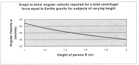
Figure 4 shows o against R for this case. Therefore for subjects of varying heights R, the corresponding o reflects the required angular velocity for the subject to experience an
overall centrifugal force equal to the gravitational force experienced on Earth.
FIGURE 4-ANGULAR VELOCITY REQUIRED FOR A TOTAL CENTRIFUGAL FORCE EQUAL TO EARTHS GRAVITY, FOR SUBJECTS OR VARYING HEIGHT WITH THE CENTER OF ROTATION AT THE HEAD.
2.2.2 Coriolis force
The Coriolis force is an inertial force, which appears in a rotating environment. The force is applied to an object moving linearly within the rotating environment, and deflects the object at right angles to the direction of motion. The magnitude of the Coriolis force depends on the velocity of the object and not its position. The Coriolis force as observed in the rotating frame of reference is given by
Fc= -2m(oxV), (11)
Where m = mass of moving object, o = angular velocity of rotating environment and V= linear velocity of particle. It can be seen from equation 11 that any object moving in a
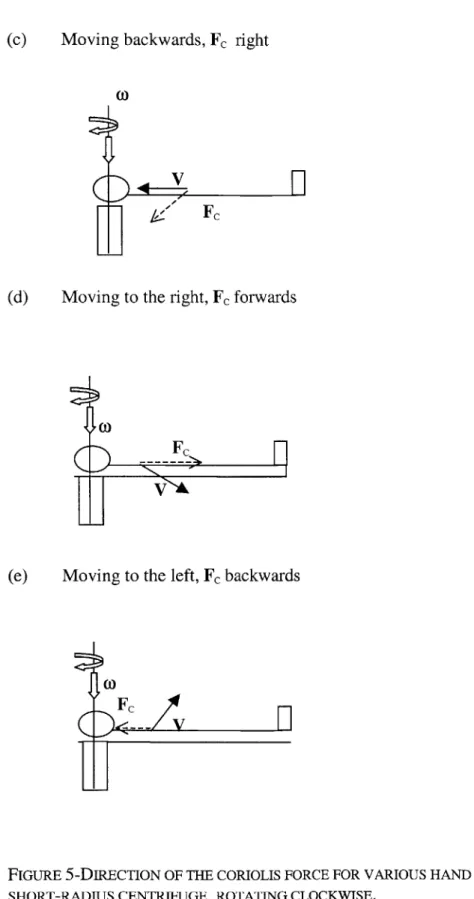
illustrates the direction of the Coriolis force for various hand movements on a short-radius centrifuge, rotating clockwise.
(a) Moving up and down parallel to the axis of rotation, Fc = 0
L
V
I V
(b) Moving forwards, Fc left
coFc
(
L
V
H
(c) Moving backwards, Fc right
(0)
(d) Moving to the right, Fc forwards
t,0
(e) Moving to the left, Fc backwards
Fc
-- V
n
I
FIGURE 5-DIRECTION OF THE CORIOLIS FORCE FOR VARIOUS HAND MOVEMENTS ON A
(t)
Coriolis forces are likely to cause postural problems when arms and legs move in a non-parallel direction to the axis of rotation.
2.2.3 Gravity gradients
Short-radius centrifugation exposes the body to a 100% gravity gradient, with 0 gravity at the head (providing the head is centered on the axis of rotation) and 100% gravity at the feet. The gravity gradient is due to the dependence of the centrifugal force on the radius of rotation. Large gravity gradients (>1g at the feet) affect the cardiovascular system and cardiovascular parameters. Further details can be obtained from Hastreiter (1997).
2.2.4 Effect of making head turns in a rotating environment on the semicircular canals
Rotation of the head (or whole body) about an axis which is itself on a rotating platform about a different axis, results in instantaneous accelerations about a third axis. Turning the head in such a rotating environment generates cross-coupled angular accelerations that induce motion of the fluid in the semicircular canals. This induced motion is not normally stimulated in the orthogonal direction when making head turns in a stationary environment. In addition to the cross-coupling stimulus, vertical semicircular canals are being brought in and out of the plane of rotation during yaw head movements when lying supine on a centrifuge. This results in a velocity change (either increase or decrease) equal to the angular velocity of the centrifuge, in the plane of the canals. This velocity change causes fluid motion in the vertical semicircular canals, resulting in illusory sensations of self or environmental motion. The vestibular stimulation conflicts with the visual stimulation. This conflict is thought to cause motion sickness (Oman, 1998). In order for the reader to fully understand the effects of making head turns in a rotating environment on the semicircular canals, a detailed description of the vestibular system is given, followed by an explanation of cross-coupled angular acceleration, and the effect on the canals of rotation into and out of the plane of rotation of the centrifuge. The section concludes with a description of the Sensory Conflict Theory of motion sickness.
The Vestibular System
Endolymphatic sac
Lateral duct (canal) Anterior ampulla Lateral ampulla Utricular macula Saccular macula Facial nerve Vestibular nerve Cochlear nerve
FIGURE 6-THE VESTIBULAR SYSTEM
The inner ear (Figure 6) consists of both the auditory and vestibular systems"'. The cochlea is the organ of hearing and the vestibular apparatus is the organ of equilibrium. The vestibular organ consists of the semicircular canals and the otolith organs. The three semicircular canals (anterior, posterior and lateral canals) detect angular accelerations, and the otolith organs (saccule and utricle) detect linear acceleration and gravity. Humans have two vestibular apparati, one on each side of the head.
Semicircular Canals
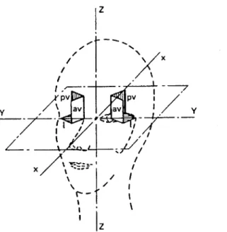
Angular acceleration (magnitude and direction) of the head is detected by the semicircular canals. The three canals are positioned approximately orthogonal to each other, this enables detection of rotation about three axes. The three canals are called the anterior, posterior and lateral canal. When the head is tilted forwards approximately 30-degrees while standing upright, the plane of the lateral canal is horizontal and the plane of the anterior and posterior canals are approximately vertical. The anterior canals project forward and outward by approximately 45-degrees, and the posterior canals project backwards and outwards by approximately 45-degrees. Although the canals do not lie in the roll, pitch and yaw axes of the skull, the brain is able to resolve the rotation detected by the receptors in the canals (into these orthogonal axes). For simplicity, future discussions will equate anterior, posterior and lateral with the head axis, and use the terms roll, pitch and yaw canals. Figure 7 shows the planes of the semicircular canals with respect to the head.
z
X
PV I I
ypv av v p v
1Z
FIGURE 7 - PLANES OF THE SEMICIRCULAR CANALS WITH RESPECT TO THE HEAD. X,Y AND Z ARE THE PRINCIPLE AXES OF THE HEAD. L, AV AND PV REFER RESPECTIVELY TO THE LATERAL (HORIZONTAL), ANTERIOR VERTICAL AND POSTERIOR CANALS.
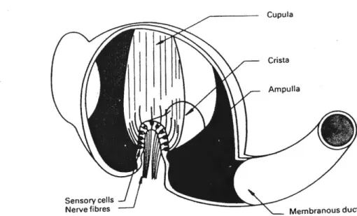
The canals are filled with a viscous fluid called endolymph. Near the junction of the canals with the utricle, each canal swells to form the ampulla, as shown in Figure 6. The sensory cells are located on the floor of the ampulla, in a saddle-shaped ridge called the crista ampullaris. Extending from the sensory cells is the cupula, which forms a seal across the ampulla. It is the cupula that prevents the endoylmph fluid from freely circulating. Bundles of hair cells called cilia project from each sensory cell in the crista ampullaris, and project up into the cupula. Within each bundle, the longest hair cell is called the kinocilium, with the other hair cells (stereocilia) being graded in length, with the shortest being farthest from the kinocilium. The resting discharge of the hair cells increases when the cilia are deflected towards the kinocilium and decreases when the cilia are deflected away from the kinocilium. Deflection of the cupula, and hence the hair cells, is caused by movement of the endolymph within the canal. This results in transmission of afferent signals to the vestibular nuclei, then the ocular-motor nuclei and then the cerebellum and cerebral cortex. Figure 8 shows a view of the ampulla of a
semicircular canal, the sensory cells and the cupula.
Cupula
Crista
Ampulla
Sensory cells
Nerve fibres Membranous duct
FIGURE 8 - A CUT-AWAY VIEW OF THE AMPULLA OF A SEMICIRCULAR CANAL TO SHOW THE SENSORY CELLS AND CUPULA.
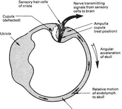
During a head turn the semicircular canals and the whole of the labyrinth move with the head. The endolymph fluid in the canals that lie in the plane of rotation lags behind the movement of the canal walls due to inertia. Thus, during angular acceleration the cupula is deflected in the opposite direction to the head rotation, due to the force between the cupula and the endolymph. The displacement of the cupula changes the afferent firing rate and therefore sends signals to the brain regarding head velocity. Figure 9 shows how the cupula is deflected by an angular acceleration in the plane of the semicircular canal.
Sensory hair cells Nerve transmitting
of crista signals from sensory
cells to brain Cupula (deflected) Ampulla .. cupula Ur e(rest position) Angular acceleration of skull Relative motion of endolymph-to skull Membranous duct
FIGURE 9 - CUPULA DEFLECTION BY AN ANGULAR ACCELERATION IN THE PLANE OF THE
SEMICIRCULAR CANAL. THE RING OF ENDOLYMPH RESISTS ANGULAR ACCELERATION
BECAUSE OF ITS INERTIA, AND A FORCE IS EXERTED ON THE CUPULA WHICH CAUSES IT TO BE DEFLECTED.
During a normal head movement in a non-rotating frame of reference, angular acceleration is followed immediately by angular deceleration. In this situation the cupula deflection and the associated signals from the sensory cells closely match the angular velocity of the head. This results in the correct sensation of a head turn. If the head
continues to rotate at constant velocity, viscous forces between the canal and the endolymph, cause the endolymph to catch up with the canal and the cupula returns to the neutral position with a time constant of approximately 6 seconds (Liefeld, 1993). Continued rotation at a constant rate therefore produces no sensation of angular motion. On cessation of rotation, the fluid pushes against the neutrally positioned cupula and deflects it in the opposite direction. The subject experiences rotation in the opposite direction. The cupula then decays back to its neutral position. The semicircular canals are stimulated by angular acceleration, however, the neural output from the sensory cells represents the angular velocity of the canal. This means that the canal is effectively performing a mathematical integration of the input signal.
Gaze Stabilization2'
During normal head movements, the gaze of the eyes may remain stabilized on a point in space (even in the dark). This stabilization is achieved by the vestibular system sending signals directly to the muscles that move the eyes. The vestibulo-ocular reflex (VOR) and nystagmus are the two main eye movements that result from activation of the vestibular system. The VOR enables one to maintain unblurred vision during head movements. If the head is turned to the left, information from the semicircular canals causes the eye to turn in the opposite direction, to the right. This compensatory eye movement occurs at the same velocity as the head movement. It is this eye movement reflex which enables the retina to remain fixed in the same point in visual space during head turns.
Nystagmus is an involuntary movement of the eye and consists of a slow phase in one direction and a fast phase (saccade) in the opposite direction. During small angles of head rotation, the compensatory eye movements created by VOR are sufficiently small to remain within the mechanical limits of eye rotation. During large angles of head rotation, the eyeball will reach a large deflection (10-30 degrees) before completion of the head
movement. In this situation, the eye is rapidly reset back to continue a new cycle of compensatory eye movements. This results in a saw-tooth pattern of eye movements, consisting of alternating slow compensatory eye movements in the opposite direction to the head turn, and rapid resetting eye movements in the direction of the head turn. Three axes of vestibular nystagmus can occur, these consist of horizontal, vertical and torsional. Head Turns in a rotating environment
Head turns in a rotating environment bring about two effects. When the head is rotated about an axis with angular velocity o%, which is itself on a centrifuge that is rotating about another axis with angular velocity oc, there is an accompanying orthogonal angular acceleration. The magnitude and direction of this accompanying orthogonal acceleration is given by the cross product of the two angular velocity vectors.
Cross-coupled orthogonal acceleration = - (wc x wk). (12)
This stimulus is only present during the head turn (which took approximately 1 second in our experiment). The second effect is due to the cupula of the canal in the plane of rotation, returning to the neutral position after several seconds of constant rotation. When a canal is taken out of the plane of rotation, it experiences a change in angular velocity equal to the angular velocity of the centrifuge. Unlike head turns in the stationary environment, the canal does not experience acceleration and then deceleration, which results in the cupula following closely the profile of the angular velocity. Following the head turn, the cupula decays back to the neutral position, with a time constant of 6 seconds. During this time the subject experiences sensations of self-motion, which last for several seconds. This second effect lasts much longer than the cross-coupling effect, and is therefore the dominant sensation. The following discussion considers firstly the effect of the cross-coupled orthogonal acceleration on the semicircular canals during head turns, and secondly the effect of moving canals in and out of the plane of rotation after the cupula has returned to the neutral position.
Cross-coupled angular acceleration
Consider a subject lying supine on a clockwise rotating centrifuge. x, y and z represent the orthogonal axes in the stationary frame of reference, where i,
j
and k are the corresponding unit vectors in the x, y and z directions respectively. x', y' and z' represent the orthogonal axes in the rotating frame of reference of the centrifuge, where i',j'
and k' are the corresponding unit vectors in the x', y' and z' directions respectively. Figure 10 shows the rotating and stationary frames of reference with the orthogonal axes labeled.Rotating frame of reference Stationary frame of reference
z' z
yy
x x
FIGURE 10 - ORTHOGONAL COORDINATE AXES IN THE ROTATING AND STATIONARY FRAMES OF REFERENCE
In the stationary frame of reference, the centrifuge has an angular velocity = -ock. A yaw head movement from right ear down (RED) to nose up (NU) in the rotating frame of reference, results in a head angular velocity = -oj'. Analysis of a vector A, which is on a rotating centrifuge of angular velocity oc, and viewed from a stationary frame of reference lead to the general expression
(dA/dt)s = (dA/dt)s, + oc x A (13)
rotating frame of reference and oc is the angular velocity of the centrifuge. By choosing A to be the position vector and linear velocity, results in the general expression for linear acceleration in a rotating environment.
a' = a - 2(oc x v') - [oc x (oc x r)] (14)
where a' is the acceleration as observed in S', a is the acceleration as observed in S, -2(oc x v') is the Coriolis acceleration acting on a body with linear velocity v' (as observed in the rotating frame of reference) and [oc x (oc x r)] is the centrifugal acceleration, where r is distance from the axis of rotation. A similar analysis can be performed using angular displacement and angular velocity rather than linear displacement and velocity, where the angular velocity on the centrifuge is caused by the subject making yaw head movements. The same analysis in angular terms yields
CH =H - MC X OH') - MC X OH) (15)
where aH' is the angular acceleration acting on the subjects head as viewed from the rotating frame of reference, aH is the angular acceleration acting on the subjects head as viewed from the stationary frame of reference, oc is the angular velocity of the centrifuge as viewed from the stationary frame of reference, oH' is the angular velocity of the head as viewed from the rotating frame of reference and oH is the angular velocity of the head as viewed from the stationary frame of reference. The dominant term in equation 15 is the cross-coupling term given by - (oc x eH'), this term represents the magnitude and direction of the cross-coupling acceleration, caused by making head turns about an axis which is different to the axis of rotation of the centrifuge. For more details regarding this derivation see French and Ebison, (1986).
Using the head and centrifuge angular velocity vectors in equation 12 (the cross-coupling term), results in a cross-coupled angular acceleration in the frame of reference of the
centrifuge = wcoki'. Firstly, consider a subject with their head in the RED position. In this position, the pitch canal is not stimulated by the cross-coupled acceleration, which acts about the x' coordinate. As the subject makes a head turn to the NU position, the pitch canal receives maximum stimulation from the cross-coupled acceleration. The magnitude of the cross-coupled acceleration applied to the pitch canal is = CWH,
modulated by a sin function to take account of the fact that the pitch canal changes orientation with respect to the stimulation axis. Therefore, the angular cross-coupled acceleration acting on the pitch canal during a yaw head turn from RED to NU,
= (oco)H(t)sin(o)H(t)t), (16)
where t is time.
The angular velocity profile of the head is a function of time, a.t(t) starts at 0 at t = 0, accelerates to peak velocity and decelerates, so the velocity is 0 when the turn angle is 90 degrees. The angular cross-coupled stimulus is modulated by this velocity profile. Just like a normal head movement when angular acceleration is followed shortly by deceleration, the cupula deflection in the pitch canal closely matches the cross-coupled velocity stimulus. The cupula is therefore deflected and returns to the neutral position in approximately the same time taken to complete the 90-degree head turn. This deflection should give a brief pitching sensation, but is probably insignificant compared to the sensation resulting from taking the pitch canal out of the plane of rotation.
The same reasoning can be applied to the roll canal. In the RED position, the roll canal experiences maximum stimulation by the cross-coupled acceleration. As the subject turns to the NU position, the roll canal is not stimulated by the cross-coupled angular acceleration. The cross-coupled angular acceleration acting on the roll canal during head turn from RED to head up is given by
= (c1)7)cos(W0t)
Since the angular velocity of the head consists of acceleration shortly followed by deceleration back to 0, the cupula deflection in the roll canals closely matches the angular velocity of the head. The cupula is therefore deflected and returns to the neutral position in the time taken to complete the 90-degree head turn. This deflection gives a brief sensation of rolling clockwise, but is probably insignificant compared to the sensation resulting from turning the roll canal into the plane of rotation. The yaw canal is unaffected by the angular cross-coupled acceleration during the head turn. Instead, the yaw canal experiences the normal head acceleration and deceleration, which results in the normal cupula response.
Turning canals into and out of the plane of rotation
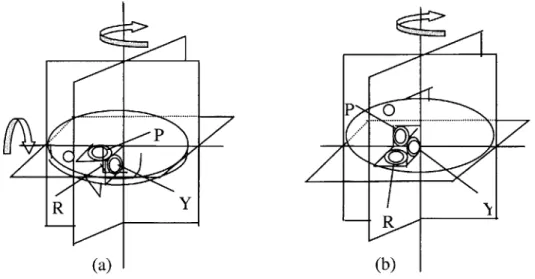
In addition to the cross-coupling acceleration described above, a second effect occurs when the canals are taken in and out of the plane of rotation, this effect dominates the sensations experienced during such head turns. Consider a subject lying RED on a clockwise rotating centrifuge as shown in figure 11.
-- ... ... P
PP
R
-Rf
(a) (b)
FIGURE 11 - POSITION OF THE SEMICIRCULAR CANALS DURING A 90-DEGREE YAW HEAD TURN FROM (A) RED TO (B) NU, ON A CLOCKWISE ROTATING PLATFORM.
In this position the pitch canal is in the plane of rotation. If the centrifuge rotates at constant velocity, after several seconds the cupula which was initially deflected due to being placed in the plane of rotation, returns to the neutral position. During a head turn from RED to NU, the pitch canal is taken out of the plane of rotation. The pitch canal experiences a change in angular velocity, equal to the angular velocity of the centrifuge (23rpm in our experiment). The endolymph decelerates in the clockwise direction with respect to the canal after the head turn, this should cause the subject to feel a sensation of pitching forwards. Unlike a normal head movement, which consists of a head acceleration closely followed by a deceleration, only a deceleration is present. Rather than the cupula closely following the velocity profile, like in a normal head turn, the absence of an acceleration immediately after the deceleration causes the cupula to decay back to the neutral position with a time constant of 6 seconds. This decay time is much greater than the 1 second cupula deflection due to the cross-coupled angular accelerations experienced during head turns.
The response of the cupula to a change in angular velocity in the plane of the canal can be modeled as a first order system. A modified Young-Oman Laplace transfer function model (Young & Oman, 1969) for rotation in the dark was used to model the cupula response to head turns on the rotating centrifuge. The cupula dynamics are assumed to be a simple exponential decay with a gain K = 1, and time constant Tc = 6 seconds. The adaptation effects are treated as another exponential decay in series with the cupula with a time constant Ta = 80 seconds. Figure 12 shows the modified Young-Oman Laplace transfer function model for the canal dynamics.
Head Ks Cupula
Velocity Deflection
(s +1/Tc) (s + 1/Ta)
Canal Dynamics Neural Adaptation
FIGURE 12 - MODIFIED YOUNG-OMAN LAPLACE TRANSFER FUNCTION MODEL FOR THE CANAL RESPONSE TO ROTATION.
Equation 18 represents the open loop transfer function for the system described in figure 12
= ks2/((s+1/Tc)(s+1/Ta)) (18)
The change in angular velocity in the plane of the pitch canal was modeled as a ramp change from 23rpm to Orpm (where 23rpm is the angular velocity of the centrifuge in our experiment). Figure 13 shows the angular velocity in the plane of the pitch canal during a RED to NU head turn, and the response of the cupula.
2.5 2-U 1.5 --0.5 E 0-C.) 0 -0.5 C) -1 -1.5 -2--2.5 0 5 10 15 20 25 30 35 40 Time (seconds)
FIGURE 13 - RESPONSE OF THE CUPULA (BLACK) TO A VELOCITY CHANGE OF 23PRMS
(2.4 RADIANS/SEC) IN ONE SECOND IN THE PITCH CANAL (DOTTED GREY), USING A MODIFIED YOUNG-OMAN LAPLACE TRANSFER FUNCTION MODEL
The roll canal is initially out of the plane of rotation (figure 11), the cupula is therefore in the neutral position. During a head turn from RED to NU, the roll canal is moved into the plane of rotation. The roll canal experiences a change in angular velocity of 23rpm (during the time taken to make a head turn (1 second)). The endolymph accelerates in the counterclockwise direction during the head turn, deflecting the cupula. This should cause the subject to feel a sensation of clockwise roll. Figure 14 shows the angular velocity in the plane of the roll canal during a RED to NU head turn, and the response of the cupula.
2.5 2 0 con c12 1.5 1 0.5 0 -0.5 0 5 10 15 20 25 30 35 40 Time (seconds)
FIGURE 14 - RESPONSE OF THE CUPULA (BLACK) TO A VELOCITY CHANGE OF 23PRMS
(2.4 RADIANS/SEC) IN ONE SECOND IN THE ROLL CANAL (DOTTED GREY), USING A MODIFIED YOUNG-OMAN LAPLACE TRANSFER FUNCTION MODEL.
The yaw canal is orthogonal to the plane of rotation of the centrifuge, and therefore experiences the normal acceleration and deceleration present during yaw head turns in a stationary environment. The yaw head turn lasts one second and the head rotates through an angle of 90-degrees (peak angular velocity of head = 3.14rads/sec). Figure 15 shows the angular velocity in the plane of the yaw canal during a RED to NU head turn, and the response of the cupula. In this case the cupula closely follows the profile of the angular velocity in the plane of the canal, the subject therefore does not experience any unusual sensations of self-motion in this plane.
- I
-3.5 II I I I I I 3 2.5 2 r-1.5 in 1 0.5-0 0.5 0 2 4 6 8 10 12 14 16 18 Time (seconds)
FIGURE 15 -RESPONSE OF THE CUPULA (BLACK) IN THE YAW CANAL TO A 90 DEGREE YAW HEAD TURN (DOTTED GREY) ON A 23PRM ROTATING DEVICE, USING A MODIFIED
YOUNG-OMAN LAPLACE TRANSFER FUNCTION MODEL.
When the reverse head movement is made from NU to RED, the pitch canal is initially out of the plane of rotation, therefore the head movement causes the canal to move into the plane of rotation. This causes the fluid to initially rotate in the counterclockwise
direction, the fluid deflects the cupula and should cause a sensation of pitching backwards. The roll canal is initially in the plane of rotation, the head turn causes the canal to come out of the plane of rotation. The fluid which was initially rotating at the same velocity as the canal in the clockwise direction of centrifuge rotation, continues to rotate but decelerates clockwise when the canal is brought out of the plane of rotation,
In addition to the perceived self-motion sensations of pitch and roll, subjects also experience a vertical nystagmus when making yaw head turns. The nystagmus is a result of fluid flow in the vertical semicircular canals and bending of the cupula, for more details see Sienko (2000).
2.3 Motion Sickness
The Sensory Conflict Theory (Oman, 1998) is one approach to explaining the cause of motion sickness. The major factors contributing towards motion sickness consist of conflicts between visual, vestibular and proprioceptive inputs, and comparison of inputs with expectations from previous experience. There are two approaches to generating motion sickness in a controlled environment, the first consists of vestibular stimulation such as the Coriolis effect caused by head rotation in a rotating environment, and the second visual stimulation. Signs and symptoms of motion sickness include nausea, pallor, headache, dizziness and in the extreme case, vomiting. In the example given in the previous section, where yaw head movements are made on a rotating centrifuge, the subject experiences unexpected self-motion in the directions described. This perceived self-motion conflicts with the visual input, and the expected internal model associated with performing yaw head turns. This motion is therefore likely to induce motion sickness.
3.
Methods
3.1 Design
This study was designed to determine the ability of humans to adapt, and retain adaptation to out-of-plane head movements made during short-radius centrifugation. The hypothesis for the experiment was as follows: Repeated exposure to a series of yaw head movements made on a short-radius centrifuge will result in a decrease in: non-compensatory vertical nystagmus, inappropriate perceived self-motion sensations and
motion sickness. Decreases in non-compensatory vertical nystagmus and inappropriate perceived self-motion sensations are expected both during the experiment and with repeated exposures, demonstrating both habituation and adaptation. Motion-sickness scores are also expected to decrease with repeated exposures.
Measures of adaptation included non-compensatory vertical nystagmus, motion-sickness scores during centrifugation, post-experiment motion-sickness scores, verbal reports of spatial orientation and computer animations of perceived self-motion. This report focuses on measurements of perceived self-motion and motion sickness. A detailed report of non-compensatory vertical nystagmus as a measure of adaptation can be found in Sienko (2000).
The study involved exposing eight subjects to three sessions of centrifugation, each lasting approximately twenty minutes. The sessions were performed on the following days: day one, day two and day eight. The centrifugation sessions were divided into three phases comprising: pre-adaptation, adaptation and post-adaptation. Subjects were required to make yaw head turns during all three phases of the experiment. Both pre- and post-adaptation phases were performed in darkness, during which eye data was collected. The adaptation phase lasted ten minutes and was performed in the light. Evidence exists (Guedry,1964) to support the theory that habituation to Coriolis stimulation is more effective with visual cues that in darkness (It is thought that when a visual reinforcement of a still fixation is provided during the habituation series, nystagmus decline may be attributable to competition between visual and vestibular systems, with vision gaining dominance). The experiment is therefore designed to measure the subject's initial reaction to the stimulus in the dark, and again in the dark after ten minutes of head movements in the light, during which adaptation is expected to occur. The design was driven by the requirement of non-compensatory vertical nystagmus measurements to be performed in darkness, due to suppression of nystagmus in the light.
3.2 Equipment
The main experimental apparatus consisted of the MIT short-radius centrifuge, an ISCAN infrared eye imaging system, Watson angular rate sensors, two 300Hz emachine computers, and a variety of tools to capture motion sickness and perceived self-motion sensations (motion-sickness surveys, verbal reports and computer animation software and hardware).
3.2.1 MIT short-radius centrifuge
The MIT short-radius centrifuge has a 2-meter radius and is designed to rotate a subject about an axis through the head. The centrifuge was built and designed by Peter Diamandis in 1988. The centrifuge is driven by a lhp electric motor through a 50:1 gear reduction. We operated the centrifuge at 23 rpm, which created alG force at the feet of a 1.67m tall subject. Counter weights were used at the head of the centrifuge to balance the moment arms, and an adjustable footplate accommodated subjects of different heights. A 32-channel slip ring located in the center of the tube support structure was used to transmit data from the centrifuge to the data acquisition system. A number of safety features were included in the centrifuge design, including side railings, a safety belt and an emergency stop button. A windshield canopy was also built by Diamandis to protect subjects from winds generated at high velocities. An on-board RCA color video camera was mounted to one end of the centrifuge and wired through the slip ring. Further details regarding the centrifuge design can be found in Diamandis, (1988). A picture of the MIT short-radius centrifuge is shown in Figure 16.
A series of modifications were carried out on the centrifuge in order to perform this study. The centrifuge velocity controller was converted from manual control to computer control. LabVIEW software (version 5.1) was used to generate velocity profiles and control the velocity of the centrifuge. A Hewlett Packard optical encoder (256CPR) was mounted to the worm gear to provide accurate velocity readings. ISCAN eye imaging goggles and Watson angular rate sensors were powered by on-board batteries and wired