Publisher’s version / Version de l'éditeur:
Vous avez des questions? Nous pouvons vous aider. Pour communiquer directement avec un auteur, consultez la première page de la revue dans laquelle son article a été publié afin de trouver ses coordonnées. Si vous n’arrivez Questions? Contact the NRC Publications Archive team at
[email protected]. If you wish to email the authors directly, please see the first page of the publication for their contact information.
https://publications-cnrc.canada.ca/fra/droits
L’accès à ce site Web et l’utilisation de son contenu sont assujettis aux conditions présentées dans le site LISEZ CES CONDITIONS ATTENTIVEMENT AVANT D’UTILISER CE SITE WEB.
Proceedings of Materials Science and Technology, pp. 720-732, 2013-10-31
READ THESE TERMS AND CONDITIONS CAREFULLY BEFORE USING THIS WEBSITE. https://nrc-publications.canada.ca/eng/copyright
NRC Publications Archive Record / Notice des Archives des publications du CNRC : https://nrc-publications.canada.ca/eng/view/object/?id=78e61e80-823d-4448-8233-0e63f39e6bf6 https://publications-cnrc.canada.ca/fra/voir/objet/?id=78e61e80-823d-4448-8233-0e63f39e6bf6
NRC Publications Archive
Archives des publications du CNRC
This publication could be one of several versions: author’s original, accepted manuscript or the publisher’s version. / La version de cette publication peut être l’une des suivantes : la version prépublication de l’auteur, la version acceptée du manuscrit ou la version de l’éditeur.
Access and use of this website and the material on it are subject to the Terms and Conditions set forth at Characteristics of electron beam welded CA6NM
Sarafan, Sheida; Wanjara, Priti; Champliaud, Henri; Mathieu, Louis; Lanteigne, Jacques
CHARACTERISTICS OF ELECTRON BEAM WELDED CA6NM
S. Sarafan1, 2,P. Wanjara2, H. Champliaud1, L. Mathieu3and J. Lanteigne4
1 École de technologie supérieure, Montréal, Québec, Canada, H3C 1K3
2 National Research Council Canada, Aerospace, Montréal, Québec, Canada, H3T 2B2 3 ALSTOM Canada Inc., Sorel-Tracy, Québec, Canada, J3R 5P9
4 Institut de recherche d’Hydro-Québec (IREQ), Varennes, Québec, Canada, J3X 1S1
Keywords: Electron beam welding, Cast CA6NM martensitic stainless steel, Microstructure.
Abstract
In this study, the viability of thick-gauge section assembly for hydroelectric turbine manufacture was considered by electron beam welding (EBW) of CA6NM martensitic stainless steel, a widely utilized hydro-turbine cast material. Particularly, bead-on-plate (BOP) trials on 60 mm-thick CA6NM plates were carried out using a 42 kW high vacuum EBW system. The influence of the heat input, beam focus (BF) position, beam defocusing, and in-situ pre-heating conditions on the characteristics of the weldments, such as the bead geometry, weld integrity, fusion zone (FZ) and heat affected zone (HAZ) microstructures and hardness were evaluate. A relationship between the welding parameters and the resulting depth of penetration was first established. A methodology for in-situ heating of the thick gauge section prior to welding was then developed and evaluated for reducing welding defects in CA6NM.
Introduction
With due consideration of the geometry and size of hydroelectric turbine elements, exigent challenges exist in manufacturing for the assembly of thick gauge section runner components. Presently, conventional fusion welding technologies are employed for assembly and repair of the turbine elements by a series of welding passes with filler metal addition. This multiple-pass arc welding/repair process is high in heat input and distortion of the assembly involves costly re-working/shaping. In addition, repeated heating to the fusion temperature during multiple-pass arc welding may also be problematic for generating a homogeneous microstructure in the weldment. That is, repeated melting during each pass results in microstructural variation within the FZ and HAZ of the previous passes that may then render inconsistencies in the performance of the assembly.
Thus, the application of a high energy density technology, such as EBW, for joining thick gauge sections with a single pass has the overall advantages of low heat input over arc welding without the need for filler metal addition and the capability of minimizing microstructural changes in the weldment [1-6]. However, as the energy of the EBW process is focused and highly localized at the weld interface, large temperature gradients can occur within the weldment [7, 8]. Hence, the temperature distribution in the weld must be understood and related to the resulting microstructural constituents in the assembly. In this regard, the parametric conditions of the EBW process thus need to be studied and optimized to achieve the required penetration in thick gauge section components whilst ensuring the weld integrity and performance. The relatively good weldability of the martensitic stainless steels, and in particular CA6NM, applied for the manufacture of turbine elements provides a reasonable premise for the development of a EBW process for the assembly of thick gauge sections. However, the cracking tendency of thick
Materials Science and Technology (MS&T) 2013 October 27-31, 2013, Montreal, Quebec, Canada Copyright © 2013 MS&T'13®
gauge section welds in martensitic stainless steel grades may require experimental strategies for mitigation. For instance, fracture of 50 mm thick SUS50 martensitic stainless steel welds was attributed by [9] to the higher cooling rate of the EBW process, which may require a thermal treatment, such as pre-heating, to lower the heating and cooling rates in the weldment. With due consideration of the geometrical and dimensional characteristics of the turbine elements, the development of a localized heat treatment procedure for in-situ EBW, e.g. electron beam zonal heat treatment (EBZHT), may provide advantages of time and energy savings, high cleanliness and efficiency, and high productivity [10, 11].
In this research the weldability of thick gauge section (up to 60 mm) CA6NM stainless steels using EBW was studied. The parametric conditions of the process (e.g. heat input, BF position, beam size) were varied to understand the influence on the weld bead geometry, defects, phase constituents and microhardness. As part of the process development work, EBZHT was deliberated utilizing a defocused electron beam and applied in-situ the vacuum chamber prior to welding to mitigate crack formation in the FZ.
Experimental Procedure
The material used was based on ASTM A743 grade CA6NM, a 13% Cr–4% Ni low carbon martensitic stainless steel with a cast microstructure that was quenched and tempered. The chemical composition of the experimental alloy is given in Table I and it is noteworthy that the carbon content is close to the upper allowable limit as defined in ASTM A743.
Table I. Chemical composition (wt.%) of CA6NM
Element C Mn Si P S Cr Mo Ni Ti wt.% 0.056 0.738 0.538 0.035 0.001 12.4 0.519 3.51 ˂0.003
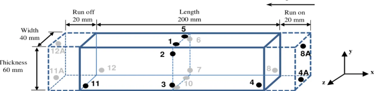
BOP welding was performed on coupons machined from as-received plates of CA6NM. Coupons were machined to have dimensions of 200 mm in length by 40 mm in width by 60 mm in thickness (t), as illustrated in Figure 1. Prior to BOP welding, the surfaces of the coupons were degreased with acetone, followed by fine grinding with a scouring pad and final cleaning with ethanol to remove any surface contamination. The coupons were then demagnetized using an enclosed demagnetizer (R.B. Annis 4.5” × 14”) followed by a surface demagnetizer (Electro-Matic model A13-1) to achieve a surface magnetic field reading between 0 and 1 gauss [12]. It is noteworthy that a residual magnetism lower than 5 gauss is recommended in [13] to prevent interference with the welding procedure. The coupons were then fixed onto the worktable of the EBW system using a clamping fixture.
BOP welding trials were performed along the length of the coupon using a 42 kW Sciaky W2000 EBW system (60 kV/700 mA) operating with pressure lower than 6.7 × 10⁻³ Pa. Different trials were conducted according to the experimental conditions identified in Table II. It is noteworthy that as the EBW parameters typically ramp up to the programmed conditions at the start of welding and ramp down to zero at the end of welding, ‘run on’ and ‘run off’ lengths were established, as identified in Figure 1. To allow a stable weld length of about 200 mm, ‘run on’ and ‘run off’ tabs, each ~20 mm in length, were tacked to the coupon on either end. The beam parameters were then adjusted and varied to target a penetration depth of 60 mm through a single vertical welding pass without any filler metal addition (Table II). Specifically, at a constant BF position of 24 mm below the top surface of the coupon, the heat input was initially increased to understand the resulting penetration in the 60 mm gauge section thickness. Changes in the BF
position, beam size (defocus), and pre-heat treatment conditions prior to welding were then employed for further development and optimization of the EBW process (Table II).
Figure 1. Schematic of the CA6NM coupon (with dimensions) used for BOP welding. The run on and run off tabs as well as the location of the different thermocouples (1-12) are indicated. It is noteworthy that the thermocouples 4 and 8 were positioned periodically on the ‘run on’ tab at positions 4A and 8A, respectively to understand the temperature variation in the ramp up region. Likewise, thermocouples 11 and 12 were positioned periodically on the ‘run off’ tab at positions 11A and 12A, respectively to understand the temperature variation in the ramp down region.
Table II. Parametric conditions for the BOP welding trials
Trial No. BF position (mm) BF/t Beam defocus Pre-heat T (ºC) HI (J⋅mm-1)
1 24 0.4 0-0 - 23.6 2 24 0.4 0-0 - 47.2 3 24 0.4 0-0 - 70.9 4 45 0.75 10% 170-250 94.5 5 60 1.0 20% 100-170 94.5 6 45 0.75 10% 100-170 94.5
The temperature distribution in the different regions of the coupons was measured using a series (~6 to 12) of K type thermocouples affixed at different locations, as illustrated in Figure 1. Wireless data recording with a Universal Wireless Thermocouple Connector (UWTC) enabled monitoring of the temperature from each thermocouple during the EBW process. For the joining conditions with a planned EBZHT cycle, an integrated process was developed to conduct the experiments entirely within the EBW system using a defocused beam that was oscillated in a circular path on the top surface of the CA6NM coupons along the longitudinal direction. Multiple EBZHT passes were conducted to achieve the required temperature ranges of 170°C-250°C or 100°C-170°C. Upon reaching the required pre-heat temperature, BOP welding trials were performed.
Each BOP weld was then sectioned transverse to the welding direction (plane Y-Z in Figure 1) to extract a specimen from within the stable region for metallographic preparation and subsequent microscopic examination. Specifically, after sectioning the BOP coupons using an abrasive cut-off wheel, the specimens were ground with 220 and 800 grit SiC papers followed by rough polishing using 6, 3 and 1 μm diamond suspensions with an alcohol based lubricant on silk polishing cloths. Final polishing was conducted using 0.05 μm colloidal silica on a porous pad. To reveal the general microstructural features, electrolytic etching of the specimens was performed by immersion at room temperature for 60 seconds in a solution of 10% oxalic acid
Width 40 mm Thickness 60 mm Length 200 mm Run on 20 mm Run off 20 mm 5 1 9 10 2 3 6 7 4 11 8 12 z x y Welding direction 4A 8A 12A 11A
with a voltage of 15 V at a current of 1.6 A using an austenitic stainless steel cathode. To improve differentiation of the various phase constituents in the general microstructure of the different regions of the weldment, the specimens were chemically etched at room temperature by immersion for 10-35 seconds in Vilella's reagent (5 mL HCl, 1 g picric acid, 100 mL methanol). Selective etching for the delta ferrite (δ) phase was performed electrolytically at room temperature in a 20% aqueous solution of NaOH (~7 seconds) with a voltage of 15 V at a current of 1.6 A using an austenitic stainless steel cathode.
An optical microscope (Olympus GX-71) was used to examine the microstructural characteristics of the weldments in the FZ and HAZ at magnifications up to 1000x. The microhardness across the welded samples was measured using a load of 500 g on a Vickers microhardness (HV) machine (Struers Duramin A300), equipped with a fully automated testing cycle (stage, load, focus, measure). For each weld condition, three hardness profiles across the weld joint, i.e. near the top, center and root, were made with an indent interval of 0.4 mm.
Results and Discussion Macroscopic Examination
At a fixed BF position, the heat input was increased systematically to establish the resulting penetration depth. Figure 2 shows that dependence of the penetration depth on the heat input is linear for EBW of CA6NM and the following relationship was determined:
PD = 0.65 HI (1)
where PD is the penetration depth and HI is the heat input. Based on Eq. 1, the heat input required for complete penetration in the 60 mm gauge section thickness was determined to be about 92 J⋅mm-1
from extrapolation. With the parametric conditions slightly modified, trial 4 was conducted to validate Eq. 1. It was discerned that at 94.5 J⋅ mm-1
, with a slightly defocused beam of 10%, complete penetration across the 60 mm gauge section thickness was possible, as revealed in Figure 2b.
As apparent in Figure 2a-b, the geometry of the weld bead evolves from a ‘V-shape’ to a ‘nail head’ as the penetration depth increases. In particular, the characteristic bead geometry of a thick gauge section weld can be divided according to Lippold [14] in two regions, namely nail head and truncated, as identified in Figure 3 for a BOP weld in CA6NM. In the nail head region (just below the upper surface of the workpiece) of the weld bead, the size of both the FZ and HAZ is significantly (30-50%) greater than that in the truncated region and gives the overall appearance of a ‘nail head’, as illustrated in Figure 3a. In the truncated region just below the nail head (Figure 3b), the change in the size of the FZ and the HAZ as a function of distance from the top was observed to be relatively minor for the CA6NM weld bead. However, towards the bottom surface of the workpiece, the width of the FZ and HAZ appears to decrease increasingly and the shape approaches a truncated ‘tear-drop’ (Figure 3c), for which Sahm and Schubert have indicated that the extent of truncation is a function of the depth below the surface [15]. Additionally within the truncated region, a ‘spike’ forms at the weld root (Figure 3d) of the CA6NM BOP welds, inevitably due to the instability in the penetration that occurs during EBW under high power density conditions. Variations in the weld root depth resulting from the tendency for spiking during EBW of thick gauge section materials was reported previously [16, 17].
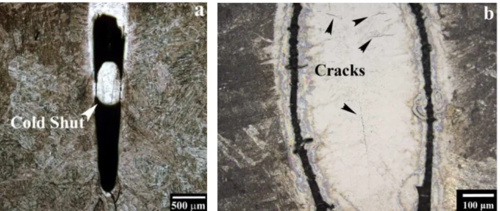
The rapid solidification conditions in the vicinity of ‘spike’ can result in gas entrapment and the occurrence of porosity in the weld root. In addition, examination of the integrity of the BOP welds in CA6NM without pre-heat treatment revealed the presence of defects such as cold shut voids at the weld root as well as cracks, as illustrated in Figure 4. Two strategies were selected to mitigate these defects, beam defocusing and pre-heat treatment.
Figure 2. (a) Relationship between the heat input and penetration depth and (b) BOP weld at 94.5 J⋅ mm-1
(trial 4 in Table II) showing full penetration in 60 mm thick CA6NM.
Figure 3. Weld bead geometry in a) nail head region, b) truncated region just below the nail head (c) truncated region showing the ‘tear drop’ shape and (d) the area of the spike at the weld root.
PD = 0.65(HI) R² = 0.998 0 10 20 30 40 50 60 70 10 20 30 40 50 60 70 80 90 100 P e n e tr at io n De p th ( mm) Heat input (J/mm) a Nail head Truncated region
Figure 4. Typical defects in CA6NM BOP welds: (a) cold shut and (b) cracking at the weld root for conditions without beam defocusing
In the case of beam defocusing, it was determined that the penetration depth decreased with increasing beam focal size, as indicated in Figure 5. Specifically, using a focused beam, full penetration across the 60 mm gauge thickness was expected at a heat input of ~92 J⋅mm-1
(according to Eq. 1), but realized at 94.5 J⋅mm-1
, as the beam was defocused by 10% in trial 4. Despite this minor compromise in the penetration depth, the application of beam defocusing was an effective strategy for improving the weld root characteristics. For instance, with a beam defocused by 10%, the spike area in the weld root exhibited some minor porosity (Figure 5a and c) due to gas entrapment as compared to the occurrence of cold shutting with a focused beam (Figure 4a). Further improvements in the weld root characteristics could be realized using a beam defocusing value of 20%; for instance the weld root area is wider and the voids have been eliminated (Figure 5b and d). However, the concomitant reduction in penetration by 50% (trial 5, Figure 5b) precludes further consideration of using a larger beam focal size as a strategy to mitigate defects beyond that achievable through defocusing by 10% (Figure 5a).
Figure 5. At the same heat input, effect of beam defocusing (a) 10% and (b) 20% on the penetration depth. High magnification imaging for regions (c) and (d) that illustrate the weld root characteristics at 10% and 20% beam defocusing, respectively.
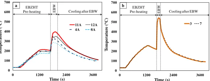
The integration of pre-heating before EBW was considered to reduce the susceptibility of the weldment to cracking. Specifically, without pre-heating of the CA6NM, the occurrence of microfissures in the FZ was observed, as revealed in Figure 6a. Initially, EBZHT was developed and temperature measurements in the different regions of the coupon, as shown, for example, in Figure 7, indicated that in-situ pre-heating of the CA6NM to an effective temperature range of 170°C to 250°C was possible. As revealed in Figure 6b, pre-heating at 170°C to 250°C was effective in mitigating the occurrence of larger cracks, but microfissures within the interdendrictic structure of the FZ remained. Pre-heating at a lower effective temperature range of 100°C to 170°C was observed to eliminate the formation of the interdendritic microfissures, as illustrated in Figure 6c. It is noteworthy that in the cast form, the CA6NM base metal (BM) has residual defects that are inherent to an as-cast microstructure, such as porosity and inclusions (that may be relatively large), which may then persist in the weldment (Figure 6d).
Figure 6. The effect of different pre-heating conditions on the characteristics of the cracks formed in the FZ (NaOH electrolytic etch): (a) without pre-heating that shows extensive cracking (b) pre-heating to 170°C-250°C that shows fine centerline cracks and (c) pre-heating to 100-170ºC that shows the absence of cracking. The defects pre-existing in the as-cast microstructure of the CA6NM BM is shown in (d).
Figure 7. Typical thermal cycles showing the temperature evolution during pre-heating at 170°C-250°C and subsequent EBW and cooling of the CA6NM during BOP welding. Labels indicate the location of the thermocouples, as identified in Figure 1, within (a) run on and off length and (b) stable weld length.
Microscopic Examination
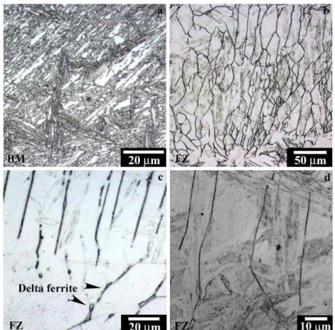
The typical evolution in the microstructure across a BOP weld in CA6NM is illustrated in Figure 8. The microstructure of the CA6NM BM consists predominately of martensite laths as shown in Figure 8a. This is consistent with that reported in [18] but depending on the heat treatment, other phase constituents may also be present, including up to 5 vol.% delta ferrite and up to 30 vol.% of retained austenite [19]. The FZ microstructure of the BOP welds consisted of columnar grains as illustrated in Figure 6c that epitaxially grow in a direction opposite to that of the heat flow. Within the columnar grains, the dendritic structure was defined by a network of delta ferrite, as revealed in Figures 8b and c. As indicated in Figure 8d, the microstructure within the dendrites was predominantly martensitic, the presence of retained austenite may also be likely, as reported in [18].
On either side of the FZ, different HAZs were apparent, as illustrated in Figure 9a. The HAZ just adjacent to the FZ (HAZ 1), often referred to as the partially melted zone (PMZ), was difficult to distinguish for the BOP welds. This finding is analogous to that previously reported for flux-cored arc welds [18] and tungsten inert gas (TIG) welding process [20] in martensitic stainless steels with a chemical composition similar to that utilized in the present work. The remaining four different HAZs that could be distinguished in the BOP welds, i.e. HAZ 2-5, have microstructures that can be understood through the ternary Fe-Cr-Ni phase diagram given in Figure 9b. In particular, heating during EBW would result in transformation of the martensite to austenite followed by delta-ferrite, depending on the temperature. Cooling after EBW then transforms the high temperature phases, such as delta ferrite and austenite, to martensite. Considering that the cooling rate after EBW is relatively rapid, compared to conventional arc welding processes, phases such as retained austenite as well as a higher fraction of delta ferrite may be present in the HAZ microstructure [18, 21].
0 100 200 300 400 500 600 700 0 1200 2400 3600 T em p er a tu re ( ºC ) Time (s) 11A 12A 4A 8A a EBZHT
Pre-heating EBW Cooling after EBW
0 100 200 300 400 500 600 700 0 1200 2400 3600 T em p er a tu re ( ºC ) Time (s) 3 7 EBZHT
Pre-heating EBW Cooling after EBW b
Figure 8. Typical evolution of the microstructure in the BOP weld (Vilella's reagent chemical etch): (a) BM and (b), (c) and (d) FZ.
Microhardness
Figure 10 reveals the typical evolution in the microhardness profile at the top, middle and bottom regions of a fully penetrated BOP weld in CA6NM. In particular, the average hardness measured for the CA6NM BM was 285 ± 9 Hv and is comparable to that previously reported (285 Hv and 300 Hv) for similar martensitic stainless steels [18, 21]. As seen from the profiles in Figure 10, the lowest and highest hardness values occurred in the HAZ. In particular, a minimum hardness of ~260 ± 20 Hv occurred in HAZ 5 and a maximum value of 430 ± 3 Hv occurred in HAZ 4, relatively close to the HAZ 4/HAZ3 boundary. Within HAZ 3 and HAZ 2 there was a progressive decrease in the hardness, such that at the FZ boundary a second hardness minimum of ~390 ± 10 Hv was apparent. The hardness then increased slightly within the FZ until the weld centerline; the average hardness minimum and maximum values in the FZ were measured to be 390 ± 10 Hv and 400 ± 7 Hv, respectively. For the BOP welds, the 5-8% softening observed in HAZ 5 relative to the BM is in agreement with the 4-6% softening calculated from the data reported in [18, 21] and has been attributed to further tempering of the martensitic structure of the as-received CA6NM that was in the quenched and tempered condition. It is noteworthy that the thermal cycle in HAZ 5 corresponds to partial transformation of the tempered martensitic structure of the CA6NM BM to austenite during heating and subsequent cooling to “virgin” (or untempered) martensite upon cooling after EBW. Considering that the hardness of the virgin martensite is higher, the hardness values in HAZ 5 will depend on the relative fraction of austenite transformed during heating (or the virgin martensite formed during cooling). As such, the scatter in the minimum hardness values in HAZ 5 is relatively high.
Figure 9. (a) Typical evolution in the microstructure from the BM to the FZ showing the different HAZs in the CA6NM BOP welds (oxalic acid electrolytic etch) that can be related to the phase transformations occurring in martensitic stainless steel as indicated in (b) the ternary Fe-Cr-Ni phase diagram [20].
Figure 10. Typical hardness evolution from the BM to the FZ at (a) top, (b) middle and (c) bottom of a BOP weld in CA6NM.
250 350 450 550 -15 -12 -9 -6 -3 0 H a rdnes s ( H v )
Distance from the weld centerline (mm) Top a
HAZ 5 HAZ 4 HAZ 3
H A Z 2 FZ 250 350 450 550 -15 -12 -9 -6 -3 0 H a rdnes s ( H v )
Distance from the weld centerline (mm)
Middle b BM HAZ 5 HAZ 4 H A Z 2 FZ H A Z 3 250 350 450 550 -15 -12 -9 -6 -3 0 H a rdnes s ( H v )
Distance from the weld centerline (mm)
Bottom c BM HAZ 5 HAZ 4 H A Z 3 H A Z 2 FZ Top Middle Bottom
a
HAZ 1 HAZ 2 HAZ 3 HAZ 4 HAZ 5b
In addition, transitioning from the hardness minimum located in HAZ 5 towards HAZ 4, the hardness increases progressively due to the increasing fraction of virgin martensite in the microstructure. In HAZ 4, the thermal cycle from EBW results in heating into the single phase austenite region; cooling after EBW should then transform the austenite to virgin martensite. Considering the short thermal exposure time during EBW, some remnant tempered martensite may persist in the microstructure, especially in the vicinity of the HAZ5/HAZ 4 boundary. Close to the HAZ 4/HAZ 3 boundary, full transformation to austenite on heating and subsequent transformation to virgin martensite on cooling then results in a hardness maximum in HAZ 4. In HAZ 3, partial transformation of the austenite to delta ferrite during heating and its subsequent presence during cooling reduces the hardness. In HAZ 2, heating into the single phase delta-ferrite region can cause rapid grain growth, which can reduce the hardness further as seen in Figure 10.
Conclusions
Based on the results of the present research on electron beam welding of a 13%Cr–4%Ni martensitic stainless steel (CA6NM), the following conclusions can be drawn:
• Pre-heating to 100-170°C followed by autogenous electron beam welding at a heat input of ~95 J⋅mm-1
(single pass) using a slightly (10%) defocused beam was demonstrated to fully penetrate 60 mm thick CA6NM and prevent welding defects, such as cold shut and cracking. • The bead-on-plate welds exhibited different heat affected zones (HAZ). Specifically, four
different HAZ were distinguishable and each region was differentiable by the particular microstructural characteristics that transpired from the thermal cycle during welding and could be interpreted from the ternary Fe–Cr–Ni phase diagram.
• The typical hardness profiles showed a hardness maximum (430 ± 3 Hv) and minimum (260 ± 20 Hv) in the HAZ 4 and HAZ 5, respectively. The average hardness in the fusion zone was between 390-400 Hv.
Acknowledgments
The authors are grateful to Alstom Canada and Hydro Quebec for supporting this project and the financial contribution of CReFaRRE and Natural Sciences and Engineering Research Council of Canada (NSERC). The authors also would like to thank X. Pelletier of NRC for his technical assistance in conducting the electron beam welding trials and metallographic preparation as well as C. Baillargeon and E. Dallaire of IREQ for their assistance related to high resolution microscopic examination.
References
1. A.H. Meleka, Electron Beam Welding: Principles and Practice (United Kingdom: McGraw-Hill for The Welding Institute, 1971).
2. K. Mills, ed., Metals Handbook: Welding, Brazing, and Soldering (Metals Park, OH: American Society for Metals International, 1983).
3. H. Schultz, Electron beam welding (United Kingdom: Woodhead Pub Limited, 1993). 4. H.B. Cary, Modern Welding Technology (Upper Saddle River, N.J.: Prentice Hall, 1998).
5. J. Norrish, Advanced Welding Processes: Technologies and Process Control (United Kingdom: Woodhead Pub Limited, 2006).
6. R.A. Lindberg, Processes and Materials of Manufacture (Boston, MA: Allyn and Bacon, 1990).
7. Q. Yunlian et al., “Electron Beam Welding, Laser Beam Welding and Gas Tungsten Arc Welding of Titanium Sheet,” Materials Science and Engineering A, 280 (1) (2000), 177-181. 8. J.W. Elmer, W.H. Giedt and T.W. Eagar, “The Transition from Shallow to Deep Penetration during Electron Beam Welding,” Welding Journal, 69 (5) (1990), 167s-175s.
9. Y. Arata, F. Matsuda and K. Nakata, “Quench Hardening and Cracking in Electron Beam Weld Metal of Carbon and Low Alloy Hardenable Steels,” Transactions of JWRI, 1 (1) (1972), 39-51.
10. F.R. Chen et al., “Effects of Electron Beam Local Post-Weld Heat-Treatment on The Microstructure and Properties of 30CrMnSiNi2A Steel Welded Joints,” Journal of Materials
Processing Technology, 129 (1) (2002), 412-417.
11. M.J. Hu and J.H. Liu, “Effects of Zonal Heat Treatment on Residual Stresses and Mechanical Properties of Electron Beam Welded Tc4 Alloy Plates,” Transactions of Nonferrous Metals
Society of China, 19 (2) (2009), 324-329.
12. A.S. Bakunov and V.F. Muzhitskii, “The Control of the Magnetisation of Components Prior to Welding Operations,” Welding International, 18 (6) (2004), 498-500.
13. UK Defence Standardization 02-855/2:2010, “Electron Beam Welding of Marine Components”, (United Kingdom: Ministry of Defence, 2010).
14. J.C. Lippold, “Centerline Cracking in Deep Penetration Electron Beam Welds in Type 304L Stainless Steel,” Welding Journal, 64 (5) (1985), 127s-136s.
15. P.R. Sahm and F. Schubert, “Solidification Phenomena and Properties of Cast and Welded Microstructures”, Proceedings of International Conference on Solidification and Casting of
Metals (Sheffield, England: The Metals Society, University of Sheffield, 1979), 389-400.
16. D.A. Schauer and W.H. Giedt, “Prediction of Electron Beam Welding Spiking Tendency,”
Welding Journal, 57 (7) (1978), pp. 189s-195s.
17. R.E. Armstrong, “Control of Spiking in Partial Penetration Electron Beam Welds,” Welding
Journal, 49 (8) (1978), 382s-388s.
18. D. Thibault, P. Bocher, and M. Thomas, “Residual Stress and Microstructure in Welds of 13% Cr–4% Ni Martensitic Stainless Steel,” Journal of Materials Processing Technology, 209 (4) (2009), 2195-2202.
19. P.D. Bilmes, M. Solari and C.L. Llorente, “Characteristics and Effects of Austenite Resulting from Tempering of 13Cr–NiMo Martensitic Steel Weld Metals,” Materials Characterization, 46 (4) (2001), 285-296.
20. D. Carrouge, H. Bhadeshia and P. Woollin, “Effect of δ-Ferrite on Impact Properties of Supermartensitic Stainless Steel Heat Affected Zones,” Science and Technology of Welding and
Joining, 9 (5) (2004), 377-389.
21. J. Enerhaug, Ø. Grong and U.M. Steinsmo, “Factors Affecting Initiation of Pitting Corrosion in Super Martensitic Stainless Steel Weldments,” Science and Technology of Welding and
Joining, 6 (5) (2001), 330-338.