Automated
Handling of Flexible Materials
by
John Charles Briggs
B.S., Massachusetts Institute of TIchnology (1986)
Submitted to the Department of Mechanical Engineering in Partial Fulfillment of the Requirements for the Degree of
Master of Science in Mechanical Engineering
at the
MASSACHUSETTS INSTITUTE OF TECHNOLOGY FEBRUARY 1988
© John C. Briggs 1988
The author hereby grants'to M.I.T. and Charles Stark Draper Laboratory permission to reproduce and to distribute copies of this thesis
document in whole or in part.
Signature of Author
Department o echanical Engineering
February 10, 1988 Certified by_
Ming Kai Tse Thesis Supervisor Accepted by
Ain Ants Sonin Chairman, Department Committee
(IAR 1 8 1988
Exhibit C
ENGINEERING INTERNSHIP PROGRAM SCHOOL OF ENGINEERING
MASSACHUSETTS INSTITUTE OF TECHNOLOGY Cambridge, Mass. 02139
THESIS REVIEW LETTER
Attention: Subject:
John R. Martuccelli, Director, Room 1-211 Master's Thesis of jo]hn C. Rrg
(student name)
The attached thesis, Automated Handling of Flexible (Title)
has been reviewed by the undersigned Draper Laboratory
(company name)
representatives and confirmed that it does not contain details objectionable
from the standpoint of Draper Laboratory
(company, name)
In addition, we understand that the aforementioned thesis report becomns the permanent property of M.I.T., will be placed in the M.I.T. Library within one month of the date of submission and may not be published wholly or in part except by authorization of the Department of Mechanical Engineerin
(department name) in which the student is enrolled.
granted o the Company for such contractual obligations may requi
Draper Laboratory I
Company Name Dire
of S
Approved By (for company)
Title:,' -,=
(It is understood that authorization is imited publication as the Company's prior re.)
c/C ompany Supervisor 'student Name tudent
Date: /
2-/
/8
7
'
MARTUCCLL
pD C ? i981.
./zJ
I t
,7- d7
Materials0
Date:1111,17
Automated Handling of Flexible Materials
byJohn Charles Briggs
Submitted to the Department of Mechanical Engineering on February 19, 1988 in Partial Fulfillment of the Requirements for the Degree of Master of Science in
Mechanical Engineering
Abstract
Apparel manufacturers have turned to automation as a means
to reduce anufacturing costs. Several recent developments, such
as the fully automated suit sleeve assembly line at Draper Labs, are showing promise to fulfill this goal. This assembly line uses fairly complex hardware, including robot folders and vision systems to replace existing manual processes. Unfortunately, the planning and execution of picking up and folding garment pieces remains very complicated. Much expertise and trial-and-error are still needed to determine the folding sequences.
One of the major problems with robot folding is to determine how to pick up pieces of cloth with the robot's end-effector. The end-effector is composed of a multiplicity of single point
pick-up devices called pickers. This thesis presents the
framework of an expert system for determining suitable sets of picker locations. The problem is that if the pickers are not picking up the cloth at suitable locations, the cloth will distort and get folded under itself. The expert system uses rules to determine picker placement parameters. The development of these rules is based on analytical models and empirical methods. Two of the key rules are the inter-picker spacing rule
and the picker-to-edge rule. The inter-picker spacing rule
relates cloth shear stiffness to the distance between adjacent pickers. The picker-to-edge rule relates the fabric bending stiffness and the coefficient of friction of the folding surface to the maximum distance between any picker and the cloth edge.
The development and solution of an elastica cloth model was vital to the development of the picker-to-edge rule. The model consists of a heavy elastica contacting a frictional surface. The solution was found on an IBM PS/2 Model 50 using Runge-Kutta integration and the shooting method of solving a two-point boundary value problem. The solution revealed three possible modes of behavior, depending on the coefficient of friction of the folding surface and a dimensionless heavy elastica parameter.
Thesis Supervisor: Dr. Ming Kai Tse
Title: Assistant Professor of Mechanical Engineering
3
-Acknowledgment
This thesis work was performed at The Charles Stark Draper Laboratory in Cambridge, MA as part of an automated tea-sile equipment project under the sponsorship of Textile Clothing Technology Corporation (TC)2. Their support is much appreciated
I owe a great deal to the Program Manager, William Toth, for his support throughout the year and a half that it took to write
this thesis. I would also like to thank all the people at the lab that I consulted with on a day-to-day basis, particularly Peter Wender, Philip Wiener, William Henrickson, Charles Elder, David Barrett, Edward Bernardon, Michael Foley, Ann Ito, and Edward Lane.
My utmost appreciation goes out to Professor Ming Kai Tse, for being my advisor on this thesis. His support and guidance has helped shape my future as a mechanical engineer.
Last, but certainly not least, I would like to thank my wife Sue Ellen. Without her, I don't think I could have endured my long stay at M.I.T. Her encouragement and humor helped to strengthen me against a sometimes heartless institution. This thesis is dedicated to Sue Ellen.
-4-Table of Contents
Abstract...
...
2
Acknowledgment
...
3...3
Table of Contents
...
4
Table of Figures
...
71 Automated Apparel Manufacturing and (TC)2 ... 11
1.1 Introduction ...11
1.2 The Road to Automation ... 13
1.3 Draper Labs' Automated Sleeve Machine ...17
1.4 Expert System for Folding ...27
1.5 Expert System for Picker Locations ...29
1.6 Overview ...35
2 Automated Apparel Manufacturing
-Basic Hardware
... 372.1 Sensors for Flexible Materials . ...37
2.1.1 Introduction ...37
2.1.2 Photoelectric Sensors ...38
2.1.3 Pneumatic Sensors ...44
2.1.4 Ultrasonic Sensors ...53
2.1.5 Capacitive Sensors ...55
2.1.6 Inductive Proximity Sensors ...57
2.1.7 Contact Sensors ...57
2.1.8 Thermal Sensors ...58
2.1.9 Electrostatic Sensors ...60
3 Automated Assembly of Men's Dress Pants...
3.1 Introduction... 3.2 Comparison of Automated and Manual Pants As! 3.3 Design for Automated Assembly ... 3.4 Layout of an Automated Factory ... 3.5 Discussion of Pants Assembly Line...
4 Non-linear
Cloth Beam
Bending
Model
...
4.1 Introduction... 4.2 Bernoulli-Euler Beam Model... 4.3 Computer Solution of Elastica Problem... 4.4 Solution by Shooting Method ... 4.5 Hints on Solving Heavy Elastica Problem...
. , , . . o ... . ,o o.. .. ,... . o.. .oo. o. . . .. .o * . .0... .. .,. o.,. . , oe*****. .,.,.*..,.
4.6 Results of Heavy Elastica Program ...119
A )
...
62
..63 ..65 ..68 ..70 ..71 ·.73 ..78 ..79 .. 79 .. 79 ..82 ..84 ·.84 ..86 ..87 .88 .96 102 102 103 108 109 114 . .... .... .v-6-4.7 Experimental Results of Cloth Heavy Elasticas... 4.8 Conclusions ...
5 Rule for
Inter-Picker
Spacing
...
5.1 Inter-Picker Spacing Problem ... 5.2 Inter-Picker Spacing Criterion... 5.3 Discussion...
6 Expert System for Picker Locations
...
6.1 Introduction ...
6.2 Picker Placement Expert System... 6.3 Rules for Picker Placement Expert System... 6.4 Picker Placement Examples... 6.5 Adding New Rules to Expert System ... 6.6 Optimization of Picker Locations... 6.7 Hardware Limitations... 6.8 Conclusions...
7 Discussion of Picker Placement Method
...
8 Conclusions
...
References...
Appendix A: Pants Assembly
Instructions ...
Appendix
B:
Runge-Kutta Numerical
Integration ...
Appendix C: Computer Code for Elastica Model.
..128 ..137 ..138 ..138 ..144 ..149 ..150 ..150 . 150 ..155 ..157 ..174 ..177 ..178 ..179 .. 181 ..184 ..186 ..187 ..216
...
218
-7
Table of Figures
The (TC)2 Automated Sleeve Machine ...18
A Schematic of The (TC)2 Sleeve Machine ...19
(TC)2 Sewing Module of the Sleeve Machine ...20
Interlocking Belt Banks ...22
(TC)2 Folder Module of the Sleeve Machine ...23
Pick and place of a suit sleeve ...30
Picker locations for a suit sleeve ...32
Thru-Beam Photoelectric Sensor ... 39
Retro Reflective Photoelectric Sensor ...41
An Optical Displacement Sensor ...43
Clippard 1022 Proximity Switch ...46
Gagne SFX18 One Sided Proximity Detector ...47
Gagne SFX8 Thru-gap Adjustable Sensor Gagne SFX8DR Thru-gap Sensor... Clippard 1030 Miniature Gap Sensor... Gagne Cross Jet Gap Sensor... A Capacitive Proximity Switch... Contact Sersor on a Conveyor Belt... A Walton Cloth Picker ... Clupicker Made by Jet Sew... Polytex Cloth Picker (Swiss made)... MARS Pick-up Device (Singer)... Vortex Vacuum Picker (Ann Ito)... ... 49
...
50
... 51 ... 52 ... 56 ...64. 59 ... 64 ... 66 ... 69 ... 72 ... 74Figure 2-17: Experimental Adhesive Picker... Figure Figure Figure Figure Figure Figure Figure Figure Figure Figure Figure Figure Figure Figure Figure Figure Figure Figure Figure Figure Figure Figure Figure 1-1: 1-2: 1-3: 1-4: 1-5: 1-6: 1-7: 2-1: 2-2: 2-3: 2-4: 2-5: 2-6: 2-7: 2-8: 2-9: 2-10: 2-11: 2-12: 2-13: 2-14: 2-15: 2-16:
.... ... ... 76
-
8-Durkopp Adhesive Picker... (TC)2 End Effector for Sleeve Machine. Top View of (TC)2 End-Effector ... Proposed Flexible End-Effector... Figure 3-1: Automated Pants Assembly Line.
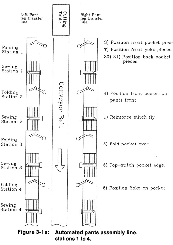
... 77 ... 80 ... 81 ... 83
...
90
Folding/Sewing Station 3 ...95Automated Factory of "Upper Wear. ...99
Conceptional Ideas of Automated Sewing System... 100
Diagram of Elastica Beam Geometry ...105
Static Equilibrium of Elastica Element ...107
Boundary Conditions for BEAM.EXE Program ...lll Multiple Solutions for Elastica... ... 116
Elastica 1.5 inch long, -0.5... Elastica 1.5 inch long, -0.8... Elastica 1.5 inch long, -1.4... Elastica 2.0 inch long, -0.1... Elastica 2.0 inch long, p-0.3... Heavy Elastica Mode Graph... Friction Measurement Test... Kawabata Bending Stiffness Tester... Bending Stiffness of Wool/Poly Suit Material Bending Stiffness of Heavy Elastica Mode Picker Placement for ..120 ..121 .. 122 ..125 ..126 ..127 ..129 ..132 ..134 Xerox Paper ...135
Graph and Data ...136
i 6 inch square cloth ...139
Figure 5-2: Excessive Shearing Between Pickers ...141 Figure 5-3: Cloth Catenary between pickers...
Figure Figure Figure Figure 2-18: 2-19: 2-20: 2-21: Figure Figure Figure Figure Figure Figure Figure Figure Figure Figure Figure Figure Figure Figure Figure Figure Figure Figure Figure 3-2: 3-3: 3-4: 4-1: 4-2: 4-3: 4-4: 4-5: 4-6: 4-7: 4-8: 4-9: 4-10: 4-11: 4-12: 4-13: 4-14: 4-15: 5-1:
.:
..1.42- 9
-Figure 5-4: Bistable Cloth Between Pickers ...143
Figure 5-5: Picker Locations for a Pants Pocket ...145
Figure 5-6: Elastica Model of an Area of Pants Pocket ...146
Figure 5-7: Measuring Inter-Picker Deflections ...148
Figure 6-1: Modules of the Expert System ...151
Figure 6-2: Pants Pieces (V) and (P) ...158
Figure 6-3: Selecting Edge to be Moved ...159
Figure 6-4: Expert System Highlights the Selected Edge ...160
Figure 6-5: User Inputs Cloth Data ...162
Figure 6-6: First Two Pickers on Pants Piece (V) ...164
Figure 6-7: Placing Picker #6 on Pants Piece (V) ...165
Figure 6-8: Picker Placement Completed ...167
Figure 6-9: First Five Pickers Placed on the Inseam ...168
Figure 6-10: Picker #6 is Incorrectly Positioned ...170
Figure 6-11: Picker #6 is Correctly Placed on the Inseam ....171
Figure 6-12: Inseam Picker Placement is Completed ...172
Figure 6-13: Pants Pocket (S) ...173
Figure 6-14: Pickers #2 & #3 on Pants Pocket (S) ...175
Figure 6-15: All Four Pickers on Pants Pocket (S) ...176
Figure A-1: Manual Assembly of Pants Steps 1 through 7 ...191
Figure A-2: Manual Assembly of Pants Steps 8 through 13 ...192
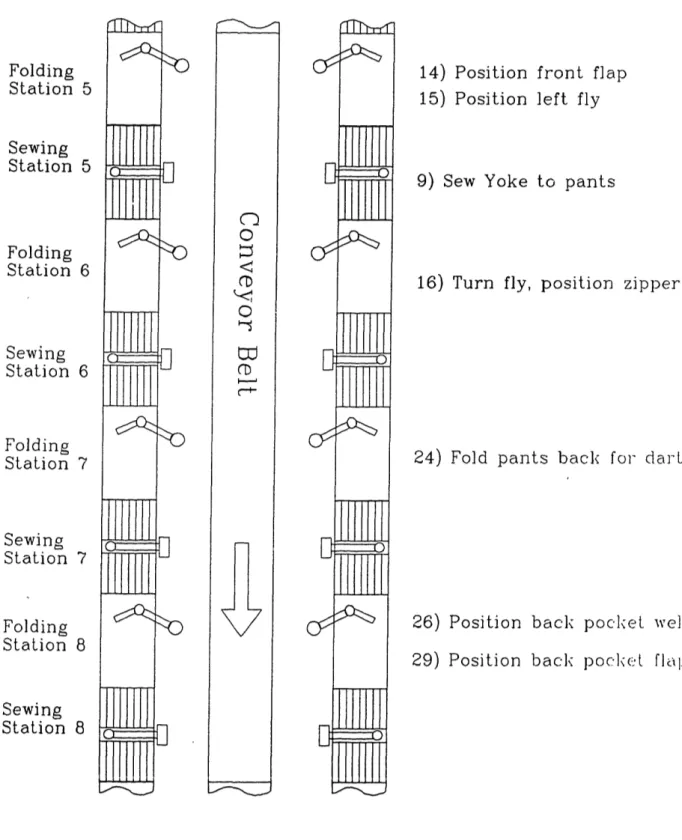
Figure A-3: Manual Assembly of Pants Steps 14 through 19 ....193
Figure A-4: Manual Assembly of Pants Steps 20 through 25 ....194
Figure A-5: Manual Assembly of Pants Steps 26 through 31 ....195
Figure A-6: Manual Assembly of Pants Steps 32 through 37 ....196
- 10
-Figure A-8: Manual Assembly of Pants Steps 44 through 49 ....198
Fire A-9: Manual Assembly of Pants Steps 50 through 55 ....199
Figure A-10: Station 1, Assembling Pocket Pieces ...205
Figure A-11i: Station 2, Attaching Pocket to Pants Front ...206
Figure A-12: Station 3, Sewing Front Pocket Edge ...207
Figure A-13: Stations 4 and 5, Attaching Yoke ...208
Figure A-14: Stations 6, 7, and 8, Zipper, Dart, Pocket ...209
Figure A-15: Stations 9 and 10, Pants Inseam & Outseam ...210
Figure A-16: Manual Finishing, Finish Back Pocket ...211
Figure A-17: Manual Finishing, Finish Zipper ...212
Figure A-18: Manual Finishing, Waistband & Crotch Seam ...213
Figure A-19: Manual Finishing, Hem Pant Leg ...214
- 11
-I Automated Apparel
Manufacturing and (TC)
2 1.1 IntroductionOne of the largest consumer manufacturing industries is the apparel industry. In 1982 the U.S. apparel industry had shipments exceeding 15.6 billion dollars. It is an industry that fills an essential need and thus its market is relatively stable. Increasing competition from foreign manufacturers, however, has put many U.S. manufacturers out
of business, and put all others on notice.
The apparel industry is typically very labor intensive. About 35% of the cost of apparel in the U.S. is labor1.
Consequently, the low cost of labor in countries like Taiwan, Korea, Philippines, etc., allows imports to sell for about 20% less than similar U.S. goods even after the application of import duties2. Furthermore, the United States' distaste for "protectionism" has left the U.S. apparel industry to fend for itself. In order to compete with foreign imports, U.S. apparel manufacturers have sought to reduce the labor intensity in garment manufacturing through automation.
Although individual companies have attempted some forms of automation, the largest apparel automation program is that of the Tailored Clothing Technology Corp, (TC)2. (TC)2
12
-was founded in 1979 as an organization to advance the state of automation in the apparel industry through research and
development.
(TC)
2is a consortium of Apparel
manufacturers, unions, and the U.S. federal government. Although the list of (TC)2 members has grow to 60+, the
original participants were Amalgamated Clothing and Textile Workers Union, Burlington Industries, Collins & Aikman Corp., Milliken & Co., Russell Corp, J.P. Stevens & Co., Greif Companies Div. of Genesco, Hartmarx Corp., Palm Beach Inc., Surgikos of Johnson & Johnson Co., Celanese Fibers Operations, E.E. duPont de Nemours & Co., and U.S.
Department of Commerce. The cooperation among these
companies, who are normally fierce competitors, is truly commendable. The feeling in the apparel community is that "We are all in the same leaky boat and we must bail and row."
Shortly after the founding of (TC)2, John T. Dunlop of
Lamont University and Fred Abernathy of Harvard University conducted an apparel manufacturing study in order to determine the needs of and state of automation in the apparel industryl. Dunlop visited many factories and met with some of the leading technologists in the apparel industry. The results of this study are clear. Automation for the apparel industry is available in the areas of
13
-spreading and cutting, but is almost non-existent in joining operations, particularly sewing. The problem with automated joining stems from a lack of ability to "handle" cut pieces of fabric using machinery.
1.2 The Road to Automation
There are a number of steps in apparel manufacturing that precede the joining operation. First, of course, the fabric must be woven and placed on a roll, commonly called a bolt of cloth. Then, the fabric must be "spread" on a spreading table. Spreading is simply stacking a number of lengths of cloth, one on top of the other, so that multiple pieces will be cut during the cutting operation. After the spreading, the cloth is marked and cut. Finally, the cut stacks of pieces are bundled, tied, and sent off to be sewn.
The presence of automation in all operations preceding sewing is very strong. Although it has some problems, automatic spreading is, and has been, readily available for quite some time. Automated marking and computerized cutting have been developed within the past 5 to 10 years. Gerber Co. has a sophisticated cutting machine that uses a thin steel blade. Other companies make laser cutters and water
jet cutters. Once the fabric has been cut, however,
14
-tied and typically hand carried to an area to be sewn. There the bundles are untied and one seamstress will perform one operation, re-bundle the parts, and send them on to the next operation. Another seamstress will sew her parts and then send them on to the next operation. Transfer lines and conveyor belts are seldom used. The location and/or status of parts at any time is usually not known. The apparel factories have become warehouses of partially finished garments. It can take up to a month in some cases to get the product from the cutting table to the factory door. A need for organization and automation is clear and evident, even in the most modern apparel factories.
Before automation comes into play most factories should
get organized. Systems of conveyor belts or overhe, t
trolley racks are commercially available. The use of such systems along with logical factory layout will reduce labor
cost, inventory, and speed factory response. Factory
operators should put an end to the days of seamstresses trying to work with two bundles of 50 pieces sitting on
their table. Automation cannot cure the ills of poor
factory planning.
Automation of certain apparel sub-assemblies is quite widely available. Perhaps the most successful of all is the automatic pocket setter. An automatic pocket setter takes a
- 15
-pre-cut pocket piece; folds the edges under; the operator locates the garment in the machine; the pocket is forced down on to the top of the garment; and an automatic X-Y sewing machine sews the edges of the pocket including backtacks. Automated pocket setters save a great deal of
time during pocket setting operations. Another success
story in automation is the automated collar machines. The collar machines consists of two separate machines. The first machine automatically fuses the collar to the interfacing. The second machine top stitches the collar edge. Another noteworthy machine is the automated shirt front machine. To make the front of a man's dress shirt, a long straight edge much be folded over, sewn in two places,
and then buttons or button holes must be added. The
automated shirt front machines can do all of this. Cut pieces of shirt fronts are laid on a conveyor belt with the long straight edges up against a rail. The straight edges are forced through a "horn" which folds the edge. Then a series of one, two, or three sewing machines do the sewing. These machines work remarkably well. Other less shining examples of automation include pillow cases, blanket and towel edging, cuff sewing, and belt making. Although all of these machines, both simple and complex, have met with some success, they still only address a small percentage of all sewing operations. These examples of automation only work
16
-for simple geometry, i.e. straight edges or fixed geometry.
The goal of (TC)2 was to make a quantum leap forward in automated apparel manufacturing. Apparel automation needs more than just task-specific hardware. It needs technology that is capable, at least conceptually, of performing a large range of apparel assembly operations. (TC)2 took to task that issue. To test the viability of such a concept (TC)2 decided to choose one item with which to attempt automation. They chose the sleeve of a man's tailored suit. The choice of a suit sleeve was partly historical (a number
of the original sponsors were tailored clothing
manufacturers) and partly practical. A suit sleeve has a number of complex operations but it is not a totally threedimensional problem. Making a suit sleeve consists of
sewing the inseam incuding easing for fullness, sewing the vent (cuff), and sewing the outseam. The possibility of actually building a machine, that could automatically do all that, initially seemed very ambitious. An alternative to the sleeve was automating a suit back. But a suit back was rejected on the basis that it was too simple. A man's suit coat sleeve was the goal, and Charles Stark Draper Laboratories was chosen as the organization to build the machine.
17
-1.3 Draper Labs' Automated Sleeve Machine
Seven years and three generations of machines later, Draper Labs had completed their task. The automated sleeve machine has a totally modular design. Separate modules could be combined like boxcars of a train. Three different module types were built: loading, folding, and sewing. A picture of the complete machine is shown in Figure 1-1. The loader module takes one pair of sleeve pieces at a time and lays them on the folder module, see Figure 1-2. The sleeves pairs are stacked like shingles on the loader. The folder module folds the sleeve and positions the edges to be sewn. Once folded, a "door" on the folder module closes on the sleeve and slides it over to the sewing module. The sewing machine, which works in an X-Y fashion, sews the seam contour and eases in fullness where necessary. Once the sewing is done the sleeve is moved on to the next module for additional folding and sewing.
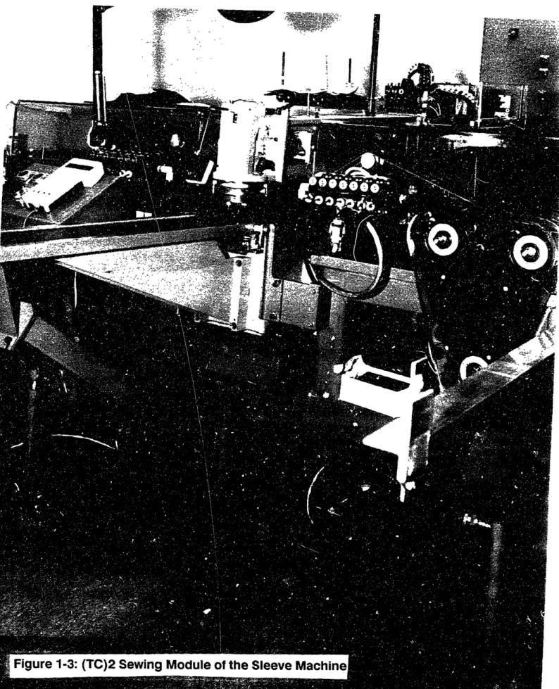
The sewing module is built much like an X-Y plotter, see Figure 1-3. The cloth is captivated by upper and lower belt banks that feed the cloth through the machine in the direction of the transfer line. A sewing machine is mounted on an enlarged frame that moves orthogonally to the direction of the belts. The combination of the sewing machine moving in one direction and the belts moving in the
9
i
/ a)a
0
E coQ, CD 0) co E Jc I, 0) I lI I-, L\, 7 s~ I ' rto 1 h(, , A I Cf/
.6'. ,-,I .d, 46-: 4- 41 I SPS9 ; · · y·J:·.jl3 iil -r`*` · · 1 ·- ' I CIi " I"I, - "L; -\1 \ I~~~..m a~~~~~n , ..119 -Folding Robot Ai tn System Sewing Module
Figure 1-2: A Schematic of The (TC)2 Sleeve Machine.
Control Electronics
\
y-Vacuum Table I r20 -I ni I
P.
v
, ,, I M.I tC 4";W
_b e tpB - LOFigure 1-3: (TC)2 Sewing
Module
of the Sleeve
I
-,'I- -7 , , ' "I I,k 1
Nammm..- , W: .
~~~~~~
·i~
x
21
-orthogonal direction allow the machine to sew virtually any two dimensional contour. In order to maintain good local control of the cloth near the needle, the traditional feeddog has been replaced with a "bulldozer" feeddog. The bulldozer has the ability to rotate about the needle so that sewing can proceed in any direction. Since the sewing head must be allowed to traverse the width of the sewing module, the belt banks are divided into two sections, one to the left and one to the right of the sewing head. In between these two belt banks is a "sewing gap" where the sewing head travels. To maintain control of the cloth in the gap a
series of interlocking belts were developed. These
"interlockers", as they are called, close around the sewing
head much like zipper teeth, see Figure 1-4. The
combination of interlocking belt banks and the bulldozer feeddog 'provides precise control of the cloth. The sleeve is eased, when necessary, by slight differential movement between the upper and lower belt banks.
The folding module consists of a robot folder, vision system, vacuum table, and a transport door, see Figure 1-5. To fold and position the sleeve parts with the required precision, it is necessary to have a vision system. The folding table surface is coated with a retro-reflective surface to improve contrast between the cloth parts and the
22
23 -Lr r
a
-4
) )w,--S
agO 'C0
6),...0
.0
5 A-' t . X - ... A:, no L_ ' W. I * _0) ,nr` meo,
IO 2 1 0 Cu f·; @ I ni~
.I'l
E- iI'
j
1*I
i tl 0o CL c Fo L I' -w- --;i"
I% 111' , I- "I,,;",;5 i ICUIIC w24
-table. The vision system locates the sleeve parts on the table and then tells the robot where key break points are so that the robot can fold the cloth properly. Beneath the folding table is a large vacuum fan that pulls air through the perforated table surface. The vacuum is used to hold the cloth down to the table while the robot is folding. The flow of air through the table is controlled by vacuum gates. The table is divided into 14 rectangular sections and the vacuum in these sections can be turned on and off via
computer control. Adjustment of the vacuum pattern is
needed when one part of a piece must remain fixed and another part must be moved. At end of a folding sequence the transport door moves over above the folding area, drops down onto the table (sandwiching the cloth against the table), and then slides the cloth over to the sewing module.
Although there are difficulties with both the sewing and folding modules, the folding module in particular needs a great deal of improvement. The sewing module is capable of sewing any contour up to and including circles. Furthermore, it is very easy to program the sewing machine. The robot/vision computers decide where to sew, create a "stitch file" and send it to the sewing computer. This makes the sewing module very flexible. Programming the folding module, on the other hand, is substantially more challenging.
25
-Programming the folder station requires consideration of a number of factors. The first step in automated folding is to take the process that the seamstress uses to make the object and change it so that it is compatible with the folding station. In some ways this is the most difficult step. The automated process usually does not look anything like the original process. Once the method and sequence of folding has been decided then trial "manual" folding begins. Manual folding consists of placing the piece of fabric on the folding table and performing, by hand, the motions of the robot. During manual folding it is decided which vacuum gates to have open.
Once the manual folding is complete, the next step is to "teach" the robot the same sequence. The manipulator is moved to the point where it is to pick up the cloth. The pickers are activated and the robot picks up the edge of the cloth and moves it to the target location. Three things could go wrong in this process: 1) The main section of the cloth did not remain stationary during the folding; 2) The cloth did not lie flat after the fold was completed; or 3) The vacuum did not hold the cloth in place when the fold was completed. These problems must be solved by changing the pick up location and folding trajectory. Once the robot
26
-folding sequence is ironed out" then the appropriate vision program must be developed so that the robot can compensate for the parts not showing up at the same location on the table every time. A detailed discussion of vision systems and vision algorithms is outside the scope of this thesis.
The difficulty of developing complete folding sequences has led to a serious lack of flexibility in the folding module. This lack of flexibility is not due to the lack of capability of the hardware, it is due to amount of time and effort that must be expended to reprogram the folder for a new size, style, or product. The lack of understanding of the folding process is the cause of most of these difficulties. The amount of trial-and-error involved in determining folding sequences must be reduced. It is important to realize that the process of developing folding
sequences, i.e. vacuum patterns, picker locations,
manipulator trajectories, etc., is not a black art. There is a reason to turn the vacuum on at a certain location at a certain time. There is a reason to place pickers at certain spots and not at others. The mechanics behind each folding sequence depends on the cloth properties, part geometry, and system environmental factors. The important properties of cloth for folding are believed to be air permeability, bending stiffness, tensile stiffness, shear stiffness,27
-creasability, coefficient of friction, and weight. These cloth properties are not usually well defined. Even if the properties were all easily available, however, ignorance of the behavior of the cloth during folding leads most people to believe that folding is a black art. This position is further reinforced by the great range of values that cloth
properties can have for different types of cloth.
Therefore, the key to shortening the development time of folding sequences is to develop a basic understanding of the physics and mechanics of cloth folding.1.4 Expert System for Folding
One possible solution to the problem of developing folding sequences is an expert system for cloth folding. Expert systems, initially developed for the medical community, have become increasingly common in other fields.
An expert system is just a computer program that uses radically new programming logic. Conceptually, the expert system would use all existing knowledge about folding (written as a set of rules), and use this knowledge to develop new folding sequences. The ideal folding expert system could take high level information like part geometry and the edges to be aligned, and develop complete vision, robot folding, and sewing sequences. Even though such a
28
-ideal system may never be realized, less-than--ideal expert systems would also be very useful. For example an expert system that could determine when to turn vacuum gates on and off. Alternatively, an expert system could determine where to place pickers on a cloth piece. An expert system could determine how high to lift the cloth off the table during folding so that the cloth folds instead of bunching. Any amount of help in determining folding sequences is valuable.
The foundation of any expert system is its rules. The rules provide the expert system the basis for making decisions. For example, consider the task of determining which vacuum gates to open. A typical rule might be, "Turn on vacuum gate if it has cloth over it." But the vacuum must be turned off along the edge that has to be move. Therefore, a second rule might be, "Don't turn vacuum on if the edge to be moved lies above that gate." Obviously the two rules will be in conflict under some conditions. Most expert systems allow the programmer to assign a confidence level to each rule. So rule number one might have a 70% confidence level and rule number two might have a 90% confidence level. When the two rules conflict, the second rule would supersede. Of course real expert systems have a great number of rules and are more complex than just described.
29
-Rules for expert systems are derived from two sources. The first source is the expert. An expert is simply a person that has a high degree of knowledge in a certain "domain." An expert gains this knowledge through the course of his work and studies. Although it is not an easy task, this knowledge can usually be written down as a set of rules that are similar to the rules that the expert uses heuristically. The other source of rules is derivation from
scientific principles. For example, in the above example of
setting vacuum pattern it is known that the pressure difference across the cloth is proportional to the air flow rate. A rule based on this is a rule based on science. The use of scientific rules is obviously very desirable. An expert system is only as good as the rules it uses. Searching for the most accurate and reliable rules of folding will help to develop the most accurate folding expert system possible.
1.5 Expert System f icker Locations
One major problem of folding is the determination of picker locations. As an example of a simple robot movement, consider aligning two edges of an inseam of a sleeve. Figure 1-6a shows the two halves of a typical suit sleeve. Before the sleeve can be sewn, the left edge of piece No. 2
30
-Figure 1-6a: Two sleeve pieces prior to alignment.
Figure 1-6b: Picker locations marked by X's on piece
number
2.
- 31
-must be aligned with the left edge of piece No. 1. If this were done on the (TC)2 machine, the vacuum would be turned on under piece No. 1 so that it remains stationary while piece No. 2 is moved. Piece No. 2 is moved by picking up along the left hand edge and dragging the piece to the left. The right half of piece No. 2 would remain in contact with the table surface and be dragged along. Once piece No. 2 is positioned above piece No. 1 it is then lowered, supposedly aligning the two left edges. Unfortunately, if the pickers are placed as shown in Figure 1-6b, the sleeve will probably end up as depicted in Figure 1-7a. As shown, a poor choice of picker locations has caused the sleeve vent to be folded under. A better choice of picker locations is shown in Figure 1-7b.
In the above example, the words "poor choice" and "better choice" were used in regard to the picker locations. One might rightly ask what is meant by a poor choice or a better choice. A good choice of picker locations is one where the cloth can be picked up, moved to a new location, and put down without having any part of the cloth get folded under or seriously distorted. There is no best choice of picker locations. However, there are picker locations that will not work, e.g. the one in Figure 1-6b. In one sense, the use of an infinite number of pickers along the edge to
32
-<--Edge folded under
Piece 2
picked up and
moved to the right
Edge folded
under
Figure 1-7a:Two sleeve pieces after failed alignment.
Note
the edges that were folded under on
piece 2.
Figure 1-7b: Better picker locations for piece 2.
The pickers are supporting the areas that
were folded under in the previous figure.
I
i_/
33
-be moved is optimum. With an infinite number of pickers, the cloth cannot get folded under. If cost is considered, an infinite number of pickers ($20-$400 each) is certainly not optimum. Even when using a finite number of pickers,
more is not necessarily better. It is true that more
pickers give better cloth control; but the better cloth control is not needed if adequate cloth control can be,-achieved with fewer pickers. It is important to realize that the cost of pickers includes cost per picker, cost of the mechanism to move the picker on the end-effector, cost of support equipment (pneumatic and/or electrical controls), and the cost of the robot (the size of which is related to the weight of the end-effector which is in turn related to the number of pickers). It is best to use a few pickers at locations that are chosen prudently.
The choice of good picker locations is not particularly
obvious. Current (TC)2 method for determining picker
locations is by trial-and-error. Consider again the picker locations shown in Figure 1-7b. This represents a good choice of picker locations for suit material. If the sleeve was made of a stiff material, like leather, this would be a poor choice of picker locations. With a stiff material, fewer pickers could be used. On the other hand if the sleeve was to be made out of a limp material, like silk, more pickers would be needed for adequate cloth control. So
34
-the choice of picker locations depends on both geometry and cloth properties. It is very difficult for a person (even an experienced one) to determine picker locations for a
complex part of various cloth properties. That is the
reason for going to an expert system.
The expert system considers all the rules at all time; but the trick to developing a good expert system is to find the rules in the first place. One way to find the rules is to consider simple problems that approximate local behavior of the cloth. In Figure 1-7b for example, what the right half of piece No. 2 is going to do is not worth considering because it has relatively little effect on the behavior of
the cloth near the pickers. On the other hand, the
coefficient of friction of cloth against the table surface is very important because it affects the behavior of the cloth edge when it is put down. By considering models of the cloth that approximate the cloth behavior near the pickers, rules for an expert system can be determined that will be capable of selecting suitable picker locations.
It might be argued by some people that an approximation of the cloth pick up process is not necessary because an "exact" solution can be obtained using a non-linear finite
35
-element program. There are a few problems with this
argument. First, this author knows of no non-linear finite element program capable of handling the problem (because it involves frictional contact and very large deflections). If such a program did exist, it would require an unreasonably long execution time. Furthermore, even if such a program did exist, it would not tell us where to place pickers. Such a program would simply take cloth geometry and picker
locations and display the deflections. If the picker
locations were good, then there is no problem. But if the picker locations were bad, there is no suggestion of where the picker should be moved to. With the use of approximate models near the pickers, the picker locations can be
determined through applications of the rules. The
advantages of using rules based on approximate model will be demonstrated later.
1.6 Overview
The goal of this thesis is to develop a methodology for
determining picker locations. Chapter 2 presents an
overview on automated apparel manufacturing hardware, including sensors, pickers, and robot end-effectors. Chapter 3 demonstrates the potential application of (TC)2 technology to pants manufacturing. The current method for manual pants assembly will be presented, then a proposed
36
-method for automated assembly using the (TC)2 machines.
Chapter 4 presents an analytical model that is used to develop an important rule for how close the pickers need to be placed to the edge of the cloth during cloth pickup. Chapter 5 presents a heuristic model that is used to determine a rule for the distance between pickers. Chapter 6 integrates the results of the last two chapters, and demonstrates the use of the rules developed in chapters 4 and 5 for picking up some of the pants pieces in chapter 3.
- 37
-2 Automated Apparel Manufacturing - Basic Hardware
There are three basic elements in an automated apparel folding system: the sensors, the pickers, and the end-effectors. The sensors are needed to locate the cloth. They can be anything from single point sensor up to two or even three dimensional vision systems. The pickers are necessary for single point pick up. A number of pickers placed on the end of a robot is an end-effector for cloth. These three components put together make up the essential hardware used for most automated apparel folding. A discussion of each of these three components follows.
2.1 Sensors for Flexible Materials 2.1.1 Introduction
The increase in automated manufacturing of textiles and other flexible materials has developed the need for a special class of sensors. These sensors must be able to detect the edge of a material that is very limp, air permeable, light permeable, very thin, acoustically soft, and has "fuzzy" edges (woven materials). Contact sensing is usually not reliable. Even a couple of grams of force is sufficient to deflect the edge of most flexible materials.
38
-Traditional non-contact methods of sensing are capable of sensing flexible materials, but can have some difficulty due to the nature of these materials.
There are several types of non-contact sensors that are useful for detecting flexible materials. These methods are optical (single element and vision systems), pneumatic, and ultrasonic. These methods and the available sensors are discussed. Also other methods of sensing are mentioned and an explanation is given as to why they will not work very well on flexible materials.
2.1.2 Photoelectric Sensors
Photoelectric sensors are by far the most widely used
sensors for flexible materials. They are fast, fairly
inexpensive, and accurate. A typical application is edge
detection of a single sheet or ply of material. For
example, a mechanism might advance a piece of cloth until the cloth was detected by a photosensor, then the edge of the cloth would be hemmed. There are two main categories of photoelectric sensors, thru-beam and reflective.
A thru-beam sensor consists of a light source and a photodetector set up in a "pitch-catch" arrangement, see Figure 2-1. When an opaque object blocks all or part of the
- 39
-LED
C
LOTH
4 -
.
·--
~--- ---
~----~;.*_
... .. ._; · . . , _-HOTODETECTOR
TABLE
2-1: Thru-Beam Photoelectric
Sensor
being used for edge
I I I I I ,.k i l4 j -P l% i I 68 1/2 W BLUE RED , , - ,BLACK 5VDC L-IEL-D ' GND: SUP VDC POWER SUPPL AMPLIFIER
Figure
-Idetection.
I40
-light from reaching the photodetector, the sensor is triggered. The amount of light that triggers the sensor is
adjustable on some models. Flexible materials are not
totally opaque, but optical sensors can still be used although some adjustment may be necessary for different materials. Small fiber optic thru-beam sensors may have sufficient accuracy that such adjustment is not necessary.
There are certain advantages and disadvantages to thru-beam sensors. One advantage is that they can travel longer distances than reflective sensors because the light beam only travels half the distance. Also, no light is lost by
reflecting off of a surface. Disadvantages are that
mounting and alignment are critical. In addition, it is sometimes difficult to incorporate thru-beam sensors into a system because the light source must be mounted on one side of the object and the photodetector on the other side.
The most reliable form of reflective photosensor is the retro-reflective scan, see Figure 2-2. The retro-reflective photoelectric sensor uses a retro-reflective target as the object to be detected. A retro-reflective material is a material that reflects light back along the same path as it came, like a road sign or bicycle reflector. In this way, a larger percentage of the light reaches the photodetector-l
1 · .
r
i~-I---
---
-
-
-
41-%;
cloth
: IIU
*'
U~~~~~~~~~~~~~
- - . .-
--
retro-reflective
surface
Sensor.
2-2: Retro Reflective Photoelectric
table
I -_ _ _
I~~
42
-This design allows the light source and the photodetector to be packaged side by side. Operation is quite simple. When no object is present, light emitted from the light source is reflected off the target into the photodetector. When an
object is present, very little light reaches the
photodetector and the sensor output is switched.The biggest advantage of retro-reflective photoelectric sensors is that sensing equipment need only be mounted on one side of the object. This advantage makes machine design simpler and less expensive. Furthermore, it makes position adjustment of the sensor very easy, since alignment and angle are not critical. For these reasons, retro-reflective photoelectric sensors are the most popular sensors among manufacturers of automated textile equipment.
There is one special type of photoelectric sensor for distance measurement, it is called an optical displacement
sensor, sea Figure 2-3. The sensor uses an LED, a
photodetector, and the method of triangulation to measure the position of the sensed object. Keyence Corp. makes two such sensors. One of their sensors has a range of ± 1 mm (0.040 inch) with an accuracy of ± 0.005 mm (0.0002 inch). The other sensor has a range of ± 5 mm (0.2 inch) with an accuracy of ± 0.020 mm (0.0008 inch). Used in pairs, these
43 -| Mu asurnP, rance Mcnitor outnul (FAR) -lV OV (JEAR; 0 v c Sec clet 4Wr /i fi 0 0 0 * 0 · I I
Bracketted vaive for PA-1801 U
Operation principle
Light emit:ing diode (LED) beam, narrowed by lens, is appiied to
object.
Diffused refiection is focused through reception lens; spot image is formed on photo detectr. Spot shifts with object dspiace-ment.
Spot position on photo detector is converted to e!ectric signal, which is transmitted to controller. Controller outputs displacement value unaffected by object
reflec-tion factor, owing to its computa-tion circuit.
Figure 2-3:
An Optical
(diagram from
Displacement Sensor.
Keyence Corp. sales literature)
(5mI (Em ]lm Fismon of colec: 0
Principle diagrm
:Cor \ Lint \ rec"ticn ens - --- --- -tnm44
-sensors can be used to determine material thickness. Another possible use would be non-contact surface texture profiling. These sensors have very limited range, therefore many applications would be better served by an ultrasonic sensor. The cost of these sensors is high, therefore other alternatives should be investigated before their use is seriously considered.
The most sophisticated form of a photoelectric sensor is a vision system. A vision system can be used to take data over a large area. To be useful, the vision data must
be processed by a computer to extract the desired
information. This is usually complicated and expensive. However, it is sometimes the only way to get the needed information about an object. This is particular true of objects that are not a simple shape, like rectangles or polygons. A discussion of vision systems is beyond the scope of this paper.2.1.3 Pneumatic Sensors
All pneumatic sensors work on the principle that any liquid or solid object will present some resistance to the flow of an air stream. This resistance will divert the air
45
-stream and cause a suitable pressure rise or drop somewhere
in the sensor. This change in pressure indicates the
presence or absence of the object being sensed.
There are two main types of pneumatic proximity sensors, the single sided back-pressure type and the two
sided thru-gap type. These types are similar to the
reflective and thru-beam photoelectric sensors. Pneumatic sensors can become very complex when the designer is trying to achieve certain goals such as fast action, long range, etc. However, the basic design is always one of the two main types. Therefore, the discussion will be limited to the basic characteristics of these two main types.
Single sided back-pressure proximity sensors only work over a very short range. Figures 2-4 and 2-5 show two different types of these sensors, made by Clippard and Gagne
Associates, respectively. Both manufacturers rate their
units to operate at a distance of 0.1 inch (2.54 cm) from the sensed object. The output pressure, at this distance, is 7.5 and 4 inches (19 and 10 cm) of water for the Clippard and Gagne, respectively. This pressure is less than 1/4 psi. Proper sensing requires either a fluid amplifier or a very sensitive pressure detector. Both these companies sell such devices. The companies claim the units work reliably even at such low pressures.
46
-1022
Proximity Switch
Type
non-contacting
air limit switch
no moving parts: will s
any flat or curved obje which presents a sensl surface of ¼4 inch or m
to the sensing nozzle
Medium-air Supply Pressure 4 psi Nominal Proximity Distance .10"W Output Signal normal: - 2" w.c. actuated: = 7.5" w.c. Frequency Response 500 CPM Air Consumption 0.3 cfm Sensing Capability flat or curvea surfaces with !,'" minimum radiu Connections 10-32 female Materials soiie brass brignt dipped SEi INT sense ct ng nore SUPPLY 4 PSIG .NSING , ERRUP' NIMUM JTPUT 5' W.C. SUPPLY
SENSING JET 1 , 0 4 PSIG
UNINTERRUPTEd
---
,
;
NEGATIVE OUTPUT...
~~~~~~~~~~~~~~~-s ~I- -- 1m 15/32-32 TH'D .40 -. 425-.31- .115 II.85
--1.15-
100" S.,C g _Proimn Duonce~Figure 2-4: Clippard
1022
Pneumatic Proximity Switch
(Diagram from Clippard Inc. sales literature)
%" I.D. TUBING SFX2 GAGE SFX12-',', (0-20" H 0) GAGE SFX12-30 (0-30 PSI) L I II "SENSIFLEX" INTERFACE I T .004 TO .020-.004 TO .020
1 /8" I.D. TUBING & JET
"Probe" Method-from
One Side of Object
Figure 2-5: Gagne SFX18 One Sided Proximity Detector.
(Diagram from Gagne Associates Inc. sales literature)
- 47
48
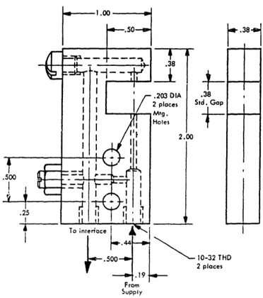
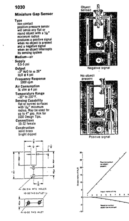
-The pneumatic gap sensors are typically more sensitive and can operate over longer distances than the back-pressure proximity sensors. Figures 2-6, 2-7, and 2-8 show three different commercial gap sensors. The gap in the sensor in Figure 2-6 is adjustable from 0 to 1.5 inch (3.81 cm) showing that these sensors do have a much larger range than the back-pressure style. The Clippard sensor, Figure 2-8, shows that for a 1/4 inch (.64 cm) gap the output pressure is about 25 inches (63 cm) of water (4 psi input). This is much more sensitive than the back-pressure sensor which had an output of only 7.5 inch (19 cm) of water at 0.1 inch (.25 cm). These sensors have an obvious alignment problem across the gap. Also, machine design is more difficult because sensing equipment must be placed on both sides of the object being sensed.
Gagne Associates make one very long range Cross Jet sensor, see Figure 2-9. In this sensor an air jet is used to deflect the path of air stream that is part of a gap sensor. When the path of the air jet is blocked by an object, the air stream flows through the gap sensor. When the air jet is not blocked, the air stream is deflected and there is no output from the gap sensor. This form of sensor is claimed to be useful for up to 18 inches (46 cm) with an air jet, or 36 inches (91 cm) using a blower.
- 49
-BASIC
PLUMBING
(gives rapid action or long gap)
Figure 2-6: Gagne SFX8
Thru-Gap Adjustable Sensor.
- 50
-
4-.38 td. Gapt
10-32 THD 2 places rrom SupplyFigure 2-7: Gagne SFX8DR Thru-Gap Sensor.
(Diagram from Gagne Associates Inc. sales literature) I-111
51
-1030
Miniature Gap Sensor Type
non.contact
positive pressure sensor will sense any flat or round object with a h"
minimum radius produces a positive signal when no object is present and a negative signal
when an object interrupts
its sensing system
Medium-air Supply 0.5- psi Output -3" H20 to X 26' H20 o 4 psi Frequency Response 1000 cpm Air Consumption ¼4 cfm 4 psi Temperature Range -30°to 230°F. Sensing Capability
flat or curved surfaces with I/2" minimum radius. May be used for
up to 4" gap. Ask for 1030 Design Tips. Connections 10-32 female Construction solid brass bright dipped 3 It I -A. _ . / ,6 Z'36 OIA MTG OLES 10-32 TH D OUTLET 10-32 TH'O INLET i 13 Positive signal 30. 25 201-. nPoutnh ouDul Homl 06e 2 3 4 6 7 8 9 10 Nelq t HO -oet oeq selllea
Figure 2-8: Clippard 1030 Minature Gap Sensor.
(Diagram from Clippard Inc. sales literature)
52 -0.5 PSI :J I to 4 PSI* INTERRUPTIBLE GAP
SMALL BLOWER OR FAN
0
0X4<211/r~~~~I
II
11
BOX 11BOX BOX
I I Hill TIVE ST AIR TS SF SWITCH OR AIR AMPLIFIER CONVEYOR FASTER BELT SLOWER BELT AIR SUPPLY "SENSIFLEX"
Figure 2-9: Gagne Cross Jet Gap Sensor.
53
-The use of pneumatic position sensors for flexible materials can have certain drawbacks. If an air jet, which is part of a sensor, is blowing on a flexible material it may have a tendency to cause the edge of the material to flutter. This would make edge detection difficult. This can be minimized by having the air jet positioned so that it tends to force the flexible material flat against the surface of the machine. Another possible problem is air leakage through permeable textiles. At best this will decrease the sensitivity of the sensor and at worst it will make them unusable (Consider a material like overlay lace). On the good side, pneumatic sensors are cheaper than photoelectric sensors. Also, many actuators in automated equipment are pneumatic and the use of pneumatic sensors allows them to be activated without electronics.
2.1.4 Ultrasonic Sensors
Ultrasonic sensing devices are capable of providing accurate distance measurement for the position of flexible materials. Ultrasonic sensors work by emitting a pulse of ultrasonic waves, having the wave reflect off an object, and catching the reflected waves. Using the elapsed time and the speed of sound, the distance to the object can be
54
-calculated. Typically the same transducer can both emit and detect the sound waves. Ultrasonic frequencies are used so that interference from background noise is minimal.
Perhaps the most well known use of ultrasonics is in
the Polaroid SX-70 series cameras. Polaroid uses the
distance information from the sensor to focus the camera lens. This sensor has a range of 0.9 to 35 feet (0.3 to 10 m) with and accuracy of ± 0.12 inch (3 mm) up to 10 feet (3 m) (± 1% over the entire range). The accuracy and the lower limit of the range is limited by the electronic circuitry. The author verified (using a test kit) that the Polaroid sensor does work on nearly all types of cloth. However, this sensor has too much range and not enough accuracy for automated assembly of flexible materials.
Other companies manufacture ultrasonic sensors
specifically for automation, for example Yodel Technology. They make an ultrasonic transducer with a range of 1 to 10 inches (2.5 to 25 cm) and an accuracy of 0.005 inch (0.1 mm). The thickness of cloth is in the range of 0.015 to 0.030 inch (0.4 to 0.8 mm). Therefore, it would be possible to detect the difference between a single layer of cloth and multiple layers of cloth. Similar transducers are available from other companies.- 55
-Ultrasonics could be a valuable sensing technique for
automated assembly of flexible materials. One of the
difficulties in using ultrasonics is detecting a soft piece of cloth on top of a hard surface, e.g. folding table. Presumably this can be done if the accuracy of the sensor is great enough. Non-contact distance measurement can be by
optical as well as ultrasonic means. However, optical
distance measurement is expensive (>$2000) and has a shorter range (± 0.5 inch (1.3 cm) typical). Ultrasonic units are somewhat cheaper but still on the expensive side ($200-$500). The expense of ultrasonics is warranted in many situations where non-contact distance measurement is needed.
2.1.5 Capacitive Sensors
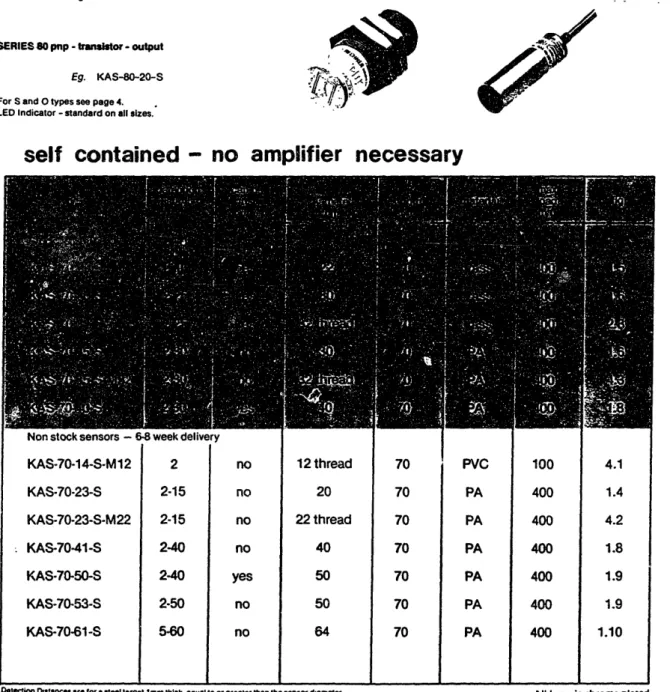
Capacitive proximity sensors detect the presence of an object by sensing its dielectric properties. These sensors use an open capacitor in an oscillating circuit. When the object being sensed passes near the sensor, the frequency of the oscillating circuit changes. Figure 2-10 shows typical specification of some industry capacitive proximity sensors.
In principle this form of sensor could be used for detecting the edge of textiles. In practice, however, one or two plies of cloth represents too small a dielectric
- '56
-CAPACITIVE SENSORS
Supply 10 -35 VDC SERIES 70 npn - transistor - output
Eg. KAS-70-20-S
SERIES 80 pup - traitor - output
Eg. KAS-80-20-S
For S and O types see page 4. LED Indicator - standard on all sizes.
RECHNER
for the detection of all materials
liquid and solid
self contained
- no
amplifier necessary
KAS-70-14-S-M12 2 KAS-70-23-S 2-15 KAS-70-23-S-M22 2-15 KAS-70-41-S 2-40 KAS-70-50-S 2-40 KAS-70-53-S 2-50 KAS-70-61-S 5-60 no no no no yes no no 12 thread 20 22 thread 40 50 50 64
Detection Dstances are for a steel target 1am thick. equal to or greater than the sensor dameter.
70 70 70 70 70 70 70 PVC PA PA PA PA PA PA 100 400 400 400 400 400 400 4.1 1.4 4.2 1.8 1.9 1.9 1.10
All brass is chrome plated
Figure
2-10:
A
Capacitive Proximity Switch.
(From Rechner Electronics Inc. sales literature)
----1
I '
-I
II
ri
_- -l i/ je
57
-change to be detected. This type of sensor is capable of sensing a stack of textiles but this is not very useful. An interesting footnote is that if the cloth were wet, the sensor could probably detect it.
2.1.6 Inductive Proximity Sensors
Inductive proximity sensors are used for non-contact sensing of metallic objects. The sensors use a probe or core wound with a coil. The coil is driven at a high frequency by an oscillator circuit. When a conductive object passes by the tip of the sensor, eddy currents are produced in the object. This additional load causes the oscillations to cease, and the output state of the sensor to change.
It is obvious that this type of sensor cannot be used to detect most flexible materials. However, it is a very useful for sensing moving parts in automated equipment.
2.1.7 Contact Sensors
The success of any contact sensing method for flexible materials depends on the flexibility of the material. Obviously, if one is working with leather, contact methods are going to be more successful than if one were working with silk. Furthermore, the success of a sensor improves as
58
-its proximity to an actuator increases. For example,
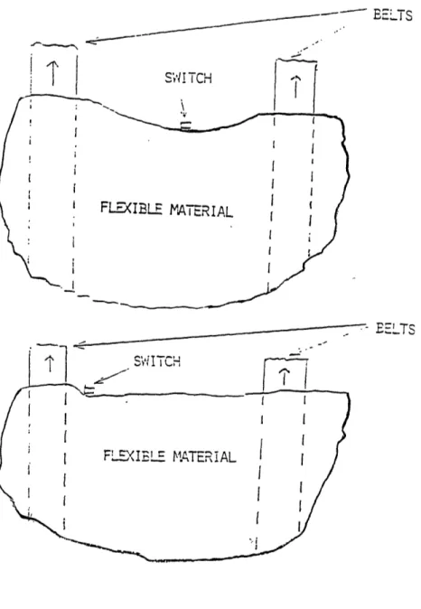
consider a piece of fabric moving along on a conveyor belt. The conveyor belt consists of two belts with a 12 inch (30 cm) wide gap between them. A limit switch, hichtriggers at one gram, is placed right in between the two belt. Another limit switch is placed right near one of the belts. The purpose of these switches is to detect the passage of cloth on the conveyor belt. It should be obvious that the switch right near the belt will distort the cloth less than the other switch, see Figure 2-11.
Most methods of contact sensing of flexible materials are not very reliable. A trip wire or hoop used to detect a cloth edge is likely to be either too stiff, distorting the cloth, or too limp, making it a hair-trigger design. Lint build up and other forms of contamination make the problem even worst. Still, in some applications, contact sensing may prove to be a useful and inexpensive means of sensing
flexible materials.*
2.1.8 Thermal Sensors
Thermal sensing would make use of the radiant
properties of the cloth to determine its position. The author knows of no commercials systems that use this principle.59
--- ELTS
S;'! iTCH
FLE(XIBLE MATERIAL
BELTS
Figure 2- 11:
A conveyor belt showing the preferred
placement of a contact sensor.
I I
Ii
i I I I II I I i I I I I I I I I60 -2.1.9 Electrostatic Sensors
Electrostatic sensing would make use of the fact that most textiles and other flexible materials pick up a static charge during manufacturing. An electrostatic charge sensor could be used as a proximity sensor for such materials.
2.1.10 Summary
Various types of sensors for flexible materials have been discussed. The advantages, disadvantages, range, accuracy, and/or application of each can be summarized as follows.
61
-1) Photoelectric sensors: fairly inexpensive(a,b)
a) Thru-beam; long range, accurate, alignment and packaging is difficult.
b) Reflective; shorter range, accurate, adjustment and packaging are easy, alignment not important
c) Optical distance measurement; very short working range, very accurate
d) Vision systems; expensive, complex, wide range of application
2) Pneumatic: inexpensive, could cause fluttering
a) Back-pressure; must be very close to object, easy to package
b) Thru-gap; longer range, packaging more difficult c) Cross-jet; very long range
.3) Ultrasonic:
Accurate distance measurement.
Detect the difference between one ply and two plies. Long range.
Moderately expensive. 4) Capacitive:
Flexible materials too thin for detection. 5) Inductive:
Used only for metals. 6) Contact:
Not reliable.
Deforms the flexible material.
Other possible methods of sensing flexible materials include thermal and electrostatic.
62 -2.2 Cloth Pickers
2.2.1 Introduction
One of the long standing problems with automated apparel manufacturing is finding a good way for the machinery to pick up pieces of cloth. The root of the problem is simply the flexible nature of the cloth. For a comparison consider a robot picking up a block of steel versus a robot picking up a suit back. For the block of steel, a simple two finger end-effector will suffice. Once the robot has picked up the block of steel, the location of all points on that block are known or can be calculated. If the same end-effector is sed to pick up the suit back, the cloth part will simply drape like a magician's handkerchief. About the only thing that is known is where the point of pick up is. An attempt to put the cloth down on a flat surface would be a futile exercise. What if the robot picked the piece of cloth up at two points? In this case, some shapes and sizes of cloth could be picked up and put down flat, but most could not. The subject of how many pickers are needed to pick up a given piece of cloth is called The multi-point pick-up problem. This discussion will be limited to how different types of single point