Tobias Bonwetsch
ETH Zurich HIL F56 8093 Zurich, SWITZERLAND [email protected] Keywords: digital fabrication, robots in architecture, CAD/CAMResearch
Robotic Assembly Processes as a Driver
in Architectural Design
Abstract. Over the last couple of years industrial robots have increasingly gained the interest of architects and designers. Robotics in architecture and construction has mainly been looked at from an engineering perspective during the latter half of the twentieth century, with the main purpose of automating the building process. Today the focus has turned towards realizing non-standardized designs and developing custom fabrication processes. However, the specific characteristics of the robot, which distinguish it from common computer numerically controlled machines, are often overlooked. Industrial robots are universal fabrication machines that lend themselves especially well to assembly tasks. Applied to architecture this resolves to the ability to control and manipulate the building process. As such, applying industrial robots emphasizes construction as an integral part of architectural design. Moreover, designing and manipulating robotic assembly processes can become a driver in architectural design. The potential of such an approach is discussed on the basis of several design experiments that illustrate that by applying such methods, form is not derived from computation or geometry, but from a physical process.
Introduction
Industrial robots are the latest addition to a number of computer numerically controlled (CNC) fabrication tools, such as routers, mills, or laser-cutters, adopted in the architectural realm over the last years.1 CNC combined with digital design tools allows
the architect to directly transfer design information to fabrication machines. This close coupling of the process of design and making has revived a notion of craft charged with the computational power of the digital tools, which act as stimulation for architectural innovation.2
However, applying robotics to construction is not a new concept and has been subject to research for over thirty years, experiencing a notably boom in the 1990s. Spearheaded by Japanese companies and universities, up until now, over 200 different prototypes of robotic solutions have been developed especially for the construction industry and tested on building sites.3 However, none of them could establish themselves
in the industry or passed the prototypical stage.4 One reason for this might be that instead of exploiting the flexibility of the machine the intention of the research was solely that of automation. Driven by economic factors, the goal was to make construction faster and cheaper, while neglecting the potential for an added value in design quality. The results were, on the one hand, highly specialized machines that automated existing construction processes. On the other hand, attempts were made to fully automate the construction of complete buildings onsite.5 Considering the specific characteristics of the building industry, where every building is unique, built in accordance to the individual clients needs and for a specific site, both concepts lacked the ability to adapt to varying building challenges and limited the possible design space.6 Overall the engineering
research missed the link to the architectural design and the potential of robots was never made available to the architect.7 Today, supported by changing technical and economic
conditions and a different conceptual approach, the question of how to exploit the flexible potential of robots and strategies on how to integrate this potential into the design process, takes on a greater role.
Robots as programmable design tools
In contrast to earlier endeavours industrial robots are now subject to design explorations.8 This rediscovery in the field of architecture benefits from changing
surrounding circumstances. Today architectural practice is no longer imaginable without the aid of information technology. CAD/CAM already allow for conceiving and realizing differentiated designs in an automated process. Although, articulated arm robots with their six axes are considerably more complex to control than common CNC machines, control systems for robots have become far more sophisticated and thereby easier to program.9 At the same time, prices of industrial robots are dropping, as manufacturers
integrate off-the-shelf personal computer technology and the overall worldwide distribution increases.
But, besides the mere availability, what makes industrial robots of particular interest as a design tool for architects and designers is their universal nature.10 Robots exhibit
specific features which distinguish them from common CNC machines, but which are often overlooked. That is, the programmability of the robot refers both to the digital control of its movement and actions, and to the definition of the physical fabrication process.11 The latter is not predefined, but dependent on the tool the robot is equipped
with. These so called end-effectors can consist of multiple tools or even be changed within a running process (fig. 1). Therefore, industrial robots allow defining the actual material manipulation, which in consequence is subject to design decisions. As the ability to program allows the architect to create his own design tools, partially freeing him from any concepts rooted in a specific CAD software, designing a robotic fabrication process opens up the freedom to follow physical processes outside the given frameworks of common CNC machines.
Fig. 1. A compilation of diverse fabrication processes realized with the same robot, but different uniquely designed end-effectors
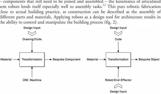
Whereas the manufacturing process of common CNC machines is component based – components that still need to be joined and assembled – the kinematics of articulated arm robots lends itself especially well to assembly tasks.12 This puts robotic fabrication close to actual building practice, as construction can be described as the assembly of different parts and materials. Applying robots as a design tool for architecture results in the ability to control and manipulate the building process (fig. 2).
Fig. 2. Diagram of CNC process (left) and robotic process (right)
Programming construction processes
By engineering project specific, or design specific, fabrication processes and thereby giving free rein to the flexibility of the robot, the direct programming of the machine becomes a necessity. In contrast, with common CNC machines applying CAM software to generate machine code from CAD drawings is the norm. However, there are numerous examples of architectural projects where the machine code is directly scripted or generated within the workflow of a digital design process.13 Nevertheless, the operational step of applying CAM software was skipped in all these projects due to reason of automating, rather than the inability of the CAM software. Especially, when dealing with a large amount of bespoke elements, programming the machine code is more efficient than generating it ‘manually’ in a CAM software by pointing and clicking. CNC machines are usually self-contained and tightly constrained in the fabrication process they perform, as well as in their working area and position of material. This makes it possible to represent and control their functionality within a general CAM software. At the easiest, fabricating a digitally described object becomes as simple as printing a piece of paper.14
Regarding flexible robotic processes, the fabrication process itself is subject to change. The robot can be equipped with completely different tools and peripheral devices and the layout of the working cell can change for each process. This means that, unlike CNC machines, the physical constraints are constantly changing and it would be impossible to foresee all potential processes beforehand in order to represent them in CAM-like software.15 Therefore, the robotic control code needs to be programed for each specific
process and account for its respective characteristics.
The control code for the robot is the encoded description of the process of making. When applying robots for additive fabrication or assembly tasks, the programming of the fabrication process is equivalent to programming the construction process. Assembly basically implies building up a three-dimensional element out of a number of single
pieces that are smaller than the final object. Naturally, the single pieces constituting the final object have to be placed and processed in a certain order to guarantee the feasibility of production. Foremost, the laws of gravity apply. Every piece placed must be supported either by already processed material, or through some kind of scaffolding (fig. 3).
Fig. 3. a, above) Fabrication of wall element. To realize the overhangs a support structure is necessary during the fabrication process; b, below) The completed installation “Structural
Secondly, the reachability of the position of placement must be assured, meaning that if more than one piece could be processed at a given point of time, the one which does not block the other pieces should be processed first. As a consequence, not only does the final structure have to be sound and stable as a whole, but it must be ensured that a stable equilibrium is achieved in each fabrication step during the build-up process.16 In
principle the same rules of common sense apply as in traditional, manual, construction. In addition, the specific anatomy of the robot, its specific end-effector, and the layout of the peripheral components has to be accounted for. This generally implies that manual processes cannot be adopted one-to-one, unless the robot and tool exhibit the same shape and dexterity as the human arm directing the tool; rather they have to be transferred and made suitable for the machine.
Through incorporating the fabrication parameters, programming the robot is the step by step description of the construction process. Of course, one can make use of standard programming techniques using subroutines, loops, conditional statements, etc., in order to structure the code and introduce variations, but in the end the robot has to perform a multitude of steps and actions in a precisely ordered sequence.
Integrating fabrication parameters into the design process
The parameters dictated by the fabrication process – besides the parameters mentioned above these also encompass the specific characteristics of the material and semi-finished products processed17 –influence the development of a design. They are at
once both constraints and opportunities. Once the fabrication parameters are identified and incorporated into the design tools, in this case through code, they open up a design space for exploration.18 In such a design space, bounded by fabrication constraints, the design exploration is deeply rooted in constructive principles and the physical reality of building.19
However, current examples operating in the broad field of digital design and fabrication very seldom choose design strategies that directly incorporate parameters of fabrication. One reason for this might be that, as described above, CAM software allows controlling common CNC machinery through drawings.20 Drawings as a means of
exploring and representation put geometry at the heart of design development. In contrast, the approach proposed of programming construction develops and generates the design out of the fabrication parameters and the necessary sequential fabrication steps.
Recent examples that integrate fabrication parameters into the design process and even apply robotics are the explorations of Brell-Cokcan, Braumann, et al. [2010] and the ‘RoboFold’ technology developed by Gregory Epps.21 ‘RoboFold’ is a sheet metal forming process, where the final form is achieved solely through folding. Possible designs are explored in a design tool that lets the user define curved fold creases and simulates the folding process. Brell-Cokcan, Braumann, et al. apply a robot for 5-axis CNC milling. In particular, flank milling strategies are pursued, thus the process creates ruled surfaces. A parametric design tool allows the user to define and control curves that represent the toolpaths of the milling tool, while incorporating certain relevant fabrication constraints such as tool length and tool diameter.
Although the examples adopt robots for fabrication they do not apply assembly or construction processes, but are limited to formative (i.e., ‘RoboFold’) or subtractive processes (i.e., milling). As a consequence they can only be applied to fabricate components and to the forming of a single piece.
Applying robotic assembly processes
A number of research projects conducted at the chair of Gramazio & Kohler for Architecture and Digital Fabrication specifically investigate robotic assembly processes. The projects combine both the design and engineering of a robotic fabrication process and consequently the application of the fabrication process on a design task. Design tools developed range from simple scripts to software applications that integrate parameters of the fabrication process (i.e., material and fabrication constraints) for design exploration. In order to broaden the results, several design explorations were carried out within the scope of experimental student courses.
As a basic method, the experiments are built up by first analyzing a manual assembly task and then transferring it to a robotic process. In doing so, aspects in the robotic process that differ from the manual work, as well as the design relevant points of intervention in the digital process control are identified.22 In a third step the
manipulation of these design relevant points, as well as fabrication constraints, are made available in software tools.
The brick projects might act as a simple example.23 The basic technique of brickwork
can be described as piling-up bricks joined by an amorphous connection (e.g., mortar) to create a greater, purposefully shaped whole. In the robotic bricklaying process a gripper attached at the end of the robot-arm places the individual bricks and bonds them with an adhesive. On the one hand, the position and rotation in space of the individual bricks is open for manipulation, while on the other hand, the necessity to follow an ordered construction sequence and limitations in possible placements of the bricks due to the specific shape and design of the gripper act as constraints. The digital control of the process allows the architect to access these parameters and activate them in his design.
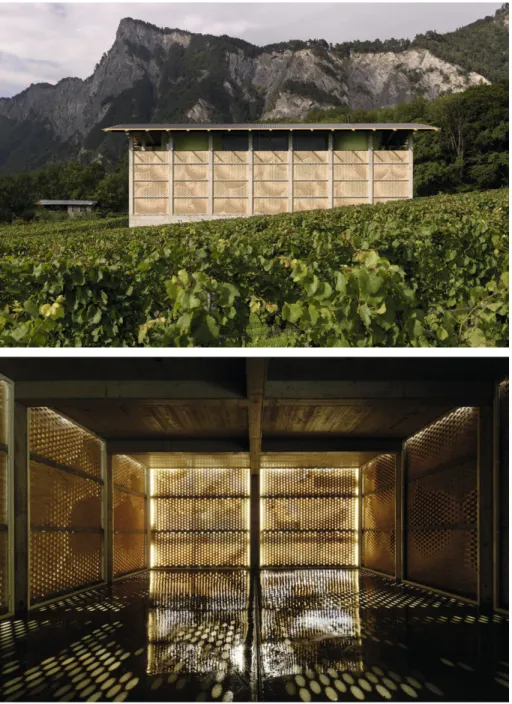
For the façade of the Gantenbein winery the bricks were positioned in a rigorous grid and solely the degree of rotation around the center axis of each brick was exploited as a design parameter, thereby allowing the display of a pattern on the façade and at the same time controlling the amount of light entering the building (fig. 4). However, the control for the oscillating wall segments of the installation at the eleventh Venice Architectural Biennale is more elaborate. The complex shape of the elements and with it the position of the single bricks is determined by the constructive requirement that the segments need to be self-supporting and firm. The resulting overhangs can only be realized by introducing support bricks that are integrated in the fabrication process (fig. 3).
More elaborated assembly processes allow optimizing material and structural efficiency through specific localized allocation of material. Furthermore, through the combination of different materials in a single fabrication process hybrid constructions can be realized that implement diverse functional and aesthetic properties. Such concepts were followed in the applied student research project on robotically fabricating outdoor furniture for the ETH campus. The assembly process consists of the layering of foam blocks joined with an adhesive. The blocks feature variable length and differing density and hardness. By means of controlled distribution of blocks with different material properties throughout the cross section it was possible to address functional requirements such as seating comfort, weight and stability. The flexibility of a backrest, for instance, could be influenced by combining blocks of different elasticity. The resulting student designs work as a communicative seating area, a bench or a private armchair, depending on their orientation (fig. 5).
Fig. 4. a, above) A pattern of spheres emerges on the façade of the Gantenbein winery; b, below) View of the interior space illustrating the light atmosphere accomplished through the
Fig. 5. a, above) Foam blocks of different density and hardness are distributed over the cross section in order to control localized performance properties; b, below) The finished furniture pieces
are coated with a layer of Polyurethane
Conclusion
The examples exhibit certain characteristics, and show advantages and potentials of programming the construction process and activating the robot as a design tool. The projects have in common that the final geometry is created through the description of the
process of making. The knowledge of making – both construction knowledge and knowledge of the tools applied – is codified and acts as driver of the design. Thereby, design and form are not primarily derived from computation or geometry, but from a physical process.
A very straightforward advantage of design through programming the fabrication process is that every design conceived within the design space spanned by the fabrication parameters is buildable and needs no post-processing. When integrating the logic of construction and the fabrication constraints in the design phase, traditional intermediate steps – those which transfer a design into something buildable – are skipped. Construction design and shop drawings that give instructions to the craftsmen and builders for the purpose of execution are eliminated. The design is thus closely connected to the physical reality of building, thereby reducing transfer loss from conception to construction.
Additionally, using code to describe a design and ultimately the process of its making takes advantage of more general aspects of notation. These are the potential to produce multiple instances of a design, as well as the possibility of inserting variation within a copy of the code. Further, through abstraction of the design, the code makes it possible to insert variables, establish relations, and implement iterations and conditionals. Programming code thus creates the frame for design exploration.24
The power of abstraction is facilitated by computers. Foremost, the computer has the ability to manage and process a large volume of data, which the robot can transfer into a physical process. Hence, the digital description of an object can be extremely specific and in consequence the code for fabrication can consist of a myriad of different instructions. As every step of the construction process has to be explicitly defined, the physical manifestation of a design can be highly informed and precisely defined down to its smallest constituent element.25
This is especially the case for programming assembly processes. With common CNC machines performing subtractive or formative fabrication processes the information in form of complexity or intelligence is introduced on the surface and the shape of the component. The single components still need to be assembled, a job that can become quite challenging for a large quantity of pieces, especially considering the potential of every component to be uniquely shaped. However, applying the concept of programming the fabrication process to assembly processes already embraces the assembly task, and additionally offers the potential to introduce complexity in the placement of the individual units that form the whole. Assembly processes allow the designer to gain control over the macro- and the micro-structure of a design and the definition of its cross section.
Acknowledgements
This paper draws upon the research work of the chair of Gramazio and Kohler for Architecture and Digital Fabrication, ETH Zurich. The author wishes to thank all people of the group involved, especially Ralph Baertschi, Fabio Gramazio, Michael Knauss, Matthias Kohler, Michael Lyrenmann, and Silvan Oesterle, as well as all the students participating in our teaching courses.
Notes
1. Several design schools around the world have installed robotic fabrication laboratories, including ETH Zurich (http://www.dfab.arch.ethz.ch/index.php?lang=e&this_page =infrastructure), Harvard Graduate School of Design (http://www.gsd.harvard.edu/inside/ cadcam/), Carnegie Mellon University (http://www.cmu-dfab.com/), the Southern California
Institute of Architecture (http://www.sciarc.edu/portal/about/resources/robotics_lab.html), University of Stuttgart (http://icd.uni-stuttgart.de/?p=4052), and others.
2. See for instance [Iwamoto 2009] and [Kolarevic 2008], which collect a number of advanced and innovative projects and experiments in the field of digital design and fabrication in architecture.
3. This number includes various mechatronic devices from completely autonomously working machines to teleoperated apparatus. Also, not all perform tasks that are strictly necessary for construction, as for instance painting. For an overview see [Bock 2008] and [Howe 2000]. 4. See [Balaguer and Abderrahim 2008].
5. The concept of a fully automated factory portal was primarily intended for high-rises. They set high constraints on the building design and additionally the typically very dense surrounding of construction sites for high-rises proved a barrier to keep up the supply chain and logistics. 6. For a discussion of the specific characteristics of the building industry see for instance [Groák
1992: 126-127]. These specific characteristics are also the reason why concepts of other manufacturing industries cannot be directly transferred to the building industry, as discussed by Richard Harris and Michael Buzzelli [2005].
7. Furthermore, the research and developments was primarily executed by process engineers. This compassed the special know-how of professional builders and architects in the construction of buildings and its direct relation to the architectural design process; see [van Gassell and Mass 2008].
8. For an overview of robotic driven design experiments conducted by the group of Gramazio & Kohler see [Gramazio and Kohler 2008].
9. Instead of positioning the robot by controlling the angles of each rotary joint, inverse kinematics and advanced controls allow moving the robot in various coordinate systems simply by defining a point in space.
10. In the patent description for a ‘Programmed Article Transfer’ – considered to be the first industrial robot – George Devol describes the object of the invention to be ‘universal automation’ and draws a direct analogy to computers. Where the latter is a ‘universal machine’ for office work – and nowadays almost all aspects of our lives – the former equals for fabrication: a general purpose machine. See [Devol 1954].
11. Many current examples indeed apply robots as a universal fabrication machine, but in a way that they only mimic other CNC machines, without activating the intrinsic potential of the robot. Although interesting projects result, but they are not specific to robotic fabrication and, for instance, might just as well have been done with a 5-axis router.
12. CNC machines have their origin in the automation of machine tools and are therefore developed to machine components, mainly through cutting or deformation. Industrial robots on the other hand, with their dexterity resembling that of a human arm, saw their first assignment in the handling of parts; see [Engelberger 2007].
13. For examples again see the collections for projects in [Iwamoto 2009] and [Kolarevic 2008]. 14. Several digital fabrication tools are already integrated as simple printer-drivers within CAD
software, such as 2D laser cutting, or 3D stereo lithography printing. Here, fabricating physical objects from a digital drawing becomes as easy as pressing the ‘print’ button.
15. This is only economically feasible for clearly specified and fixed installed robotic processes, as for instance using the robotic arm as a router.
16. Consider for instance stone arches or shell structures. Although some specific geometries allow for stable configurations during erection without the need for support, forces can only be transferred once the final geometry is achieved and can be activated.
17. If we stick to the simple process of stacking discrete pieces, the friction coefficient of the material or semi-finished product used will, for instance, influence the steepness of the angle at which single pieces can still be stacked on top of one another without shearing.
18. The potential of constraints acting as a design driver that can lead to novel design solutions is also emphasized by Axel Kilian. Although his focus is not specifically set on fabrication, independent of the types of constraints, Kilian argues that computational models and the ability to write problem specific proprietary software plays a crucial role in facilitating design explorations. See [Kilian 2006].
19. In architectural history novel forms of construction always had a great impact on design. There are several examples where architects who were also builders developed their designs directly out of assembly processes, like Brunelleschi in the early Renaissance or modern examples like Pier Luigi Nervi and Felix Candela. See [Groák 1992: 192].
20. On how the architects adopted CNC technology only once they were able to control the machines through drawing, which was made possible through the widespread introduction of CAD/CAM, rather than writing numerical code, see [Callicott 2001: 55].
21. [Tachi and Epps 2011]; see also the company’s website: http://www.robofold.com/.
22. The goal of the research projects is not automation, but to investigate architectural design potentials. Therefore, the implementation of the robotic process is focused only on those parts were the digital process control becomes relevant to design.
23. For more details on the brick projects see [Bonwetsch, Gramazio and Kohler 2007] and [Bärtschi et al. 2010].
24. On the advantage of notation cf. [McCullough 1998: 94]. 25. On how the digital may effect a new materiality see [Picon 2004].
References
BALAGUER, Carlos, and Mohamed ABDERRAHIM. 2008. Trends in Robotics and Automation in Construction. Pp. 1-20 in Robotics and Automation in Construction, Carlos Balaguer and Mohamed Abderrahim, eds. InTech. http://www.intechopen.com/books/robotics_and_ automation_in_construction. Last accessed 04.08.2012.
BÄRTSCHI, Ralph, Michael KNAUSS, Tobias BONWETSCH, Fabio GRAMAZIO, and Matthias KOHLER. 2010. Wiggled Brick Bond. Paper presented at the Advances in Architectural Geometry, Vienna, 2010.
BOCK, Thomas. 2008. Construction Automation and Robotics. Pp. 21-42 in Robotics and Automation in Construction, Carlos Balaguer and Mohamed Abderrahim, eds. In-Teh. BONWETSCH, Tobias, Fabio GRAMAZIO, and Matthias KOHLER. 2007. Digitally Fabricating
Non-Standardised Brick Walls. Paper presented at the ManuBuild, 1st International Conference, Rotterdam, 2007.
BRELL-COKCAN, Sigrid, and Johannes BRAUMANN. 2010. A New Parametric Design Tool for Robot Milling. Pp. 357-363 in ACADIA 10: LIFE in:formation, On Responsive Information and Variations in Architecture (Proceedings of the 30th Annual Conference of the Association for Computer Aided Design in Architecture (ACADIA)). New York.
CALLICOTT, Nick. 2001. Computer-Aided Manufacture in Architecture the Pursuit of Novelty. Oxford: Architectuaral Press.
DEVOL, George Charles. 1954. Programmed Article Transfer. United States Patent 2,988,237, filed 12.10. 1954, and issued 6.13.1961.
ENGELBERGER, Joseph F. 2007. Historical Perspective and Role in Automation. Pp. 3-10 in Handbook of Industrial Robotics, 2nd ed., Y. Nof Shimon, ed. Wiley Online Library, http://onlinelibrary.wiley.com/doi/10.1002/9780470172506.ch1/summary.
GASSEL, Frans van, and Ger MAAS. 2008. Mechanising, Robotising and Automating Constrcution Processes. Pp. 43-52 in Robotics and Automation in Construction, Carlos Balaguer and Mohamed Abderrahim, eds. InTech. http://www.intechopen.com/books/howtoreference/ robotics_and_automation_in_construction/mechanising__robotising_and_automating_constr uction_processes. Last accessed 04.08.2012.
GRAMAZIO, Fabio, and Matthias KOHLER. 2008. Digital Materiality in Architecture. Baden: Lars Müller Publishers.
GROÁK, Steven. 1992. The Idea of Building Thought and Action in the Design and Production of Buildings. London: E & FN Spon.
HARRIS, Richard, and Michael BUZZELLI. 2005. House Building in the Machine Age, 1920s– 1970s: Realities and Perceptions of Modernisation in North America and Australia. Business History 447, 1: 59-85.
HOWE, A. Scott. 2000. Designing for Automated Construction. Automation in Construction 99, 3: 259-76.
IWAMOTO, Lisa. 2009. Digital Fabrications Architectural and Material Techniques. Architecture Briefs. New York: Princeton Architectural Press.
KILIAN, Axel. 2006. Design Exploration through Bidirectional Modeling of Constraints. Ph.D. thesis, Massachusetts Institute of Technology.
KOLAREVIC, Branko. 2008. Manufacturing Material Effects Rethinking Design and Making in Architecture. New York: Routledge.
MCCULLOUGH, Malcolm. 1998. Abstracting Craft the Practiced Digital Hand. Cambridge, MA: MIT Press.
PICON, Antoine. 2004. Architecture and the Virtual: Towards a New Materiality? Praxis: Journal of Writing+Building 66: 114-21.
TACHI, Tomohiro, and Gregory EPPS. 2011. Designing One-Dof Mechanisms for Architecture by Rationalizing Curved Folding. In International Symposium on Algorithmic Design for Architecture and Urban Design (ALGODE-AIJ). Tokyo.
About the author
Tobias Bonwetsch is senior researcher at ETH’s Laboratory for Architecture and Digital Fabrication chaired by Gramazio & Kohler. He studied architecture and graduated from the Technical University of Darmstadt. After gaining working experience as an independent architect, he completed his postgraduate studies at the ETH Zurich with a specialisation in computer-aided architectural design. His research is concerned with integrating the logic of digital fabrication into the architectural design process, with a special focus on additive production methods. In 2010, Tobias Bonwetsch co-founded ROB Technologies, a company that develops and implements robotic manufacturing processes at the interface of architectural design and the building industry.