HAL Id: hal-00677831
https://hal.archives-ouvertes.fr/hal-00677831
Submitted on 11 Mar 2012
HAL is a multi-disciplinary open access
archive for the deposit and dissemination of
sci-entific research documents, whether they are
pub-lished or not. The documents may come from
teaching and research institutions in France or
abroad, or from public or private research centers.
L’archive ouverte pluridisciplinaire HAL, est
destinée au dépôt et à la diffusion de documents
scientifiques de niveau recherche, publiés ou non,
émanant des établissements d’enseignement et de
recherche français ou étrangers, des laboratoires
publics ou privés.
Scientific Workflow Reuse through Conceptual
Workflows
Nadia Cerezo, Johan Montagnat
To cite this version:
Nadia Cerezo, Johan Montagnat. Scientific Workflow Reuse through Conceptual Workflows.
Work-shop on Workflows in Support of Large-Scale Science (WORKS’11), Nov 2011, Seattle, United States.
pp.1-10. �hal-00677831�
Scientific Workflows Reuse through Conceptual Workflows
Nadia Cerezo
CNRS, Univ. of Nice I3S laboratory [email protected]Johan Montagnat
CNRS, Univ. of Nice I3S laboratory [email protected]ABSTRACT
An increasing number of scientific experiments are “in-silico”: carried out at least partially using computers. Scientific Workflows have become a key tool to model and implement such experiments, but they tangle domain knowledge, tech-nical know-how and non-functional concerns and are, as a result, difficult to understand, reuse or repurpose.
In order to ease Scientific Workflow Reuse, this paper de-fines a Conceptual Workflow model that is closer to the end-user’s domain and intentions. By placing our model higher on the abstraction scale, we can separate concerns and em-phasize the in-silico experiment inside the workflow, thus improving readability and re-usability.
The conceptual representation can then be transformed into a regular Abstract Scientific Workflow, exploiting both domain and non-functional knowledge that are captured and harnessed through the use of Semantic Web technologies.
Categories and Subject Descriptors
D.2.13 [Software]: Reusable software
General Terms
Scientific Workflows, Reuse, Domain Engineering
1.
INTRODUCTION
According to the Workflow Management Coalition1
, Ter-minology and Glossary 3.0, a workflow is the “automation
of a business process, in whole or part, during which doc-uments, information or tasks are passed from one partici-pant to another for action, according to a set of procedural rules”. Originally geared towards the description of
busi-ness processes, workflows have been increasingly used to describe scientific experiments, especially those performed on distributed computing infrastructures. Scientific
Work-flows are meant to perform in-silico (i.e. carried out
en-1
http://www.wfmc.org/
Permission to make digital or hard copies of all or part of this work for personal or classroom use is granted without fee provided that copies are not made or distributed for profit or commercial advantage and that copies bear this notice and the full citation on the first page. To copy otherwise, to republish, to post on servers or to redistribute to lists, requires prior specific permission and/or a fee.
WORKS’11, November 14, 2011, Seattle, USA.
Copyright 2011 ACM X-XXXXX-XX-X/XX/XX ...$10.00.
tirely or partially on computers) experiments, which usu-ally imply large amounts of data. Workflow formalisms are appealing to scientists in that they provide means to for-mally describe complex experiments using an abstract (i.e. not too tightly coupled with an execution infrastructure) and versatile (i.e. accessible and adaptable) representation. Workflows ease the design and implementation of scientific experimental protocols.
“Software Reuse is the use of existing software or software
knowledge to construct new software.” [6] Defined so broadly, Software Reuse has been an integral part of Software En-gineering from the very beginning. The general tendency
of programming languages and environments to provide de-velopers with coarser grained building blocks, at ever-higher levels of abstraction, is in itself Software Reuse. As a research area, Software Reuse lies at the crossroads of
Soft-ware Architecture (to identify and handle reusable parts), Domain Engineering (to elevate the abstraction level) and Separation of Concerns (to integrate even cross-cutting
con-cerns into reusable components).
Scientific Workflows Reuse, defined as a workflow system desideratum in [12] by “Workflow systems should make it
easy to design new workflows from existing workflows”, is
critical for two main reasons.
On the one hand, Scientific Workflows raise the need for flexibility a few notches above that of their Business coun-terparts [2]. Indeed, the scientific experiments they model result from neither precise specifications nor rigid protocols - no matter how rapidly evolving those may be - and are in-stead defined incrementally, through the exploration that is typical of scientific research. The very goal of Scien-tific Workflows, to represent in-silico experiments, entails frequent reuse and repurposing throughout their life-cycle.
On the other hand, scientific research thrives on collabo-ration between communities (e.g. teams, laboratories, coun-tries). A lot of sharing is involved in those collaborations; of knowledge as well as of know-how. Since an increasing number of communities use Scientific Workflows not only to operate their (most often data-intensive) experiments, but also to record the associated protocols and techniques, the need to share Scientific Workflows is ever-growing and from it stems a greater need for reuse and repurposing, since they enable sharing when combined with discovery (i.e. finding suitable components).
Our goal is to provide tools for workflow designers to ease reuse, repurposing and ultimately sharing of Scientific Work-flows. We believe that the main obstacle in most currently available frameworks is that their underlying models
indis-criminately mix core concerns (the high-level concepts pertaining to the end-user’s scientific domain), technical concerns (functional in that they are needed to actually enact the workflow, but not directly relevant to the mod-eled in-silico experiment) and non-functional concerns (for instance Quality of Service considerations).
Rather than building yet another framework, our proposal is to define workflows at a higher level of abstraction, up-stream from already plentiful Scientific Workflow models, then transform them into lower level workflows, readily exe-cutable by existing systems. In that, we fit the gap described in [7] as the need for distinct “dimensions of abstraction
[that] are experiment-critical versus non-experiment-critical representations, where the former refers to scientific issues and the latter is more concerned with operational matters.”
Our approach is one of Generative Reuse: new workflows are specified in a domain-specific language, then translated into executable code in a target language.
At the higher level we aim to formalize, we can overcome the aforementioned obstacle by:
• emphasizing domain concepts over technicalities, • defining separately the cross-cutting concerns and the
base process into which they are woven,
• providing a more flexible way to reuse components than the traditional encapsulation that is provided in most frameworks and
• leveraging semantic annotations to aid the design of new workflows from existing parts.
All the examples we give in the present paper, to illustrate the model we defined, come from the Virtual Imaging Platform2
(VIP) project. The project’s goal is the integra-tion of multiple modalities and organ models into a cohe-sive medical image simulation platform. The project aims to achieve (i) interoperability between various simulators that were never meant to interact, by using scientific work-flows and semantic annotations, (ii) data model federa-tion to handle all organ models in a standardized fashion, through the definition of the IntermediAte Model Format (IAMF) and (iii) reliability and performance on large-scale grid infrastructures needed to cope with the amount of data processed.
The platform is meant to be flexible and easy to extend with new simulators and organ models. To ensure maxi-mum compatibility, the integration started with four cal imaging simulators, one for each of the four main medi-cal imaging modalities: SIMRI [3] for Magnetic Resonance
Imaging (MRI); FIELD-II [10] for UltraSonography (US ); Sindbad [16] for X-ray Computed Tomography (CT); and Sorteo [15] for Positron Emission Tomography (PET).
The need for Scientific Workflow Reuse in the VIP project stems from its very objectives. Indeed, the goals of interop-erability and data model federation themselves call for the design of new - and the identification of existing - common components. Furthermore, the need for flexibility (to ease the future introduction of new simulators) has already led to the identification of common ground between the simulators at the structural level.
The model we defined has three parts and the present ar-ticle adopts the same structure: Section 2 further describes
2
http://www.creatis.insa-lyon.fr/vip/
the abstraction level at which we work and defines the high-level elements of our model. Section 3 details the process of generating a workflow at a lower level of abstraction and de-fines the elements needed in our model to perform that trans-formation. Section 4 introduces the notion of Patterns and illustrates how it could enhance Scientific Workflow Reuse. Section 5 details how and to what extent we intend to au-tomate the transformation process. We then present a few related projects in Section 6 and conclude with Section 7.
2.
CONCEPTUAL LEVEL
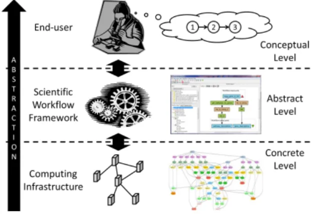
A Scientific Workflow framework is essentially an inter-face between end-users (i.e. scientists) and computing in-frastructures (most often distributed). In the field of Scien-tific Workflows, the distinction has long been made between Concrete Workflows that “bind workflow tasks to specific
resources” and Abstract Workflows that do not [17]. The
lack of stability on Grid infrastructures, where nodes and network failures are simply bound to happen every now and then, makes the manual definition of Concrete Workflows extremely impractical. As a result, most frameworks use Abstract Workflows for design as well as storage and gener-ate the Concrete Workflows automatically at runtime.
Abstract Workflows pertain to the abstraction level of the framework, thus called the abstract level, whereas Con-crete Workflows belong lower on the abstraction scale, on the infrastructure layer, thus called the concrete level. Yet, even though, as their name suggests, Abstract Work-flows are more abstract than Concrete WorkWork-flows, they are meant to be readily executable and, as such, cannot avoid the clutter of technical concerns and workarounds that are necessary for the execution.
Figure 1: Scientific Workflow Abstraction Levels To ease reuse and repurposing, we work at an higher level than that of Abstract Workflows on the abstraction scale: the so-called conceptual level, as shown on Figure 1. This level enables the modeling of in-silico experiments closer to the end-users’ domains.
The Scientific Workflow model we defined at that level is what we call Conceptual Workflow. Conceptual Work-flows aim at capturing the user intentions when he or she designs a scientific experiment, independently from concerns such as reliability, performance, security and so on. They fo-cus on the scientific process itself, distinguishing it from non-functional and technical aspects. Hence Conceptual Work-flows are easier to manipulate, understand and reuse.
2.1
Model
A Conceptual Workflow represents all or part of an in-silico experiment. At that high-level, they consist in do-main functions performed over input objects to obtain de-sired products.
Most of the existing scientific workflow models are di-rected graphs whose vertices represent data or processing nodes and whose edges represent data or control flow. We believe that representation to be straightforward enough for users who are not accustomed to process modeling and thus adopt it as a basis for our own model.
A Conceptual Workflow is a Directed Graph:
• whose vertices are Conceptual Inputs (representing input objects), Conceptual Outputs (representing desired products) or Conceptual Workflows them-selves (representing domain functions)
• and whose edges are Conceptual Links (representing the data and control flow).
Figure 2: Graphical Convention -High-level elements
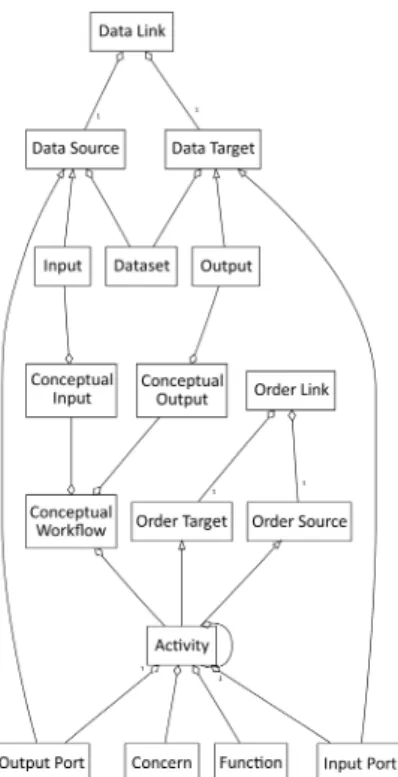
Figure 3: Meta-model - High-level elements All those elements are shown on Figure 2 and their rela-tionships are described in UML3
on Figure 3 (default cardi-nality is * (many)).
3
Unified Modeling Language, current specification available at http://www.omg.org/spec/UML/Current
Conceptual Workflows are nested so as to provide en-capsulation: parts of the workflow that are deemed too de-tailed or that are reused can be kept inside a sub-workflow and thus hidden in a black box from the viewpoint of the parent workflow. That mechanism is provided by most Sci-entific Workflow frameworks.
Each Conceptual Workflow can be associated to any number of:
• Functions: domain concepts such as Align Image or Generate Photons
• and Concerns: functions outside the scope of the domain, pertaining to a lower, more technical, level of abstraction such as Append Prefix or Convert to Stringor to cross-cutting non-functional areas of ex-pertise (e.g. Quality of Service) such as Compress dataor Retry 3 times.
Conceptual Inputs represent the starting materials of the in-silico experiment, whereas Conceptual Outputs represent its results. Both can be associated to any num-ber of Datasets: domain concepts such as Brain Model or Synthetic Sonogram.
Conceptual Links represent interactions between 3 pos-sible pairs of source/target elements:
• Conceptual Input → Conceptual Workflow, • Conceptual Workflow → Conceptual Workflow or • Conceptual Workflow → Conceptual Output.
Because a Conceptual Workflow can represent any num-ber of activities (it is often an entire sub-workflow), a given Conceptual Link can represent any number of data flows (i.e. data is transferred from the source to the target) and or any number of ordering constraints (i.e. the target starts after the source is done). Figure 8 in Section 3.1 will illus-trate that, after the definition of data flows and ordering constraints in our model.
Because in-silico experiments are inherently very data-driven, Conceptual Links will most often translate to a set of data flows. Even then, a Conceptual Link should not be confused with a Data Link, since it restrains neither number nor types of data transferred.
Let H be the set of Conceptual Workflows and R be the binary relation of Conceptual Link, the relation R is transi-tive: ∀x, y, z ∈ H, xRy ∧ yRz ⇒ xRz.
2.2
Application to VIP use case
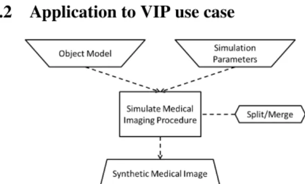
Figure 4: Highlevel Conceptual Workflow -Generic VIP simulator
To provide end-users with an interface that eases the ex-tension of the platform to new simulators, it is necessary to identify common ground between the VIP simulators al-ready in place, at the level of elements as well as at the structural level. While the four simulators considered ini-tially were developed independently and do not show much resemblance at first glance, they share a common high-level structure modeled as a Conceptual Workflow in Figure 4:
• the Object Model (OM): what is scanned by the med-ical imaging procedure (e.g. a brain, a lung),
• the Simulation Parameters (SP): procedure’s details (e.g. probe orientation, scanner dimensions),
• from those inputs, the system produces a Synthetic Medical Image (SMI)by performing the action Sim-ulate a Medical Imaging Procedure (SMIP) • and the simulation is optimized by splitting the data
over many processing resources then merging the re-sults, hence the cross-cutting non-functional concern Split/Merge, captured in a Pattern (see Section 4.1). This workflow seems generic enough to serve as a basis not only for the four simulators initially included in the platform, but also for those that will be added later on.
3.
TRANSFORMATION PROCESS
Conceptual Workflows can be used on their own, as a way to formally describe in-silico experiments at the level of the end-user’s domain, but the execution is the ultimate goal of any Scientific Workflow and thus their true use is through conversion to Abstract Workflows that can be del-egated to existing Scientific Workflow frameworks. To that end, Conceptual Workflows must embed enough information to enable their transformation into Abstract Workflows.
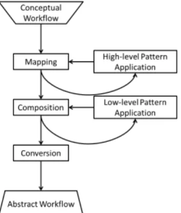
While the conversion Abstract → Concrete takes place be-tween a framework and an infrastructure and thus has to be entirely automated, the conversion Conceptual → Abstract has to rely on much user knowledge and decision-making and therefore is semi-automated at best. We will discuss how in Section 5.
Figure 5: From Conceptual to Abstract Workflow The conversion is done in 3 major steps, shown in Figure 5:
1. Mapping is the step where the scientific functions (e.g. Align Gene Sequence) are mapped to processing units (e.g. grid services) that fulfill them.
2. Composition is the step where the units found at the previous step are inter-connected.
3. Conversion is a step of translation from our model to an existing Abstract Workflow language such as
GWENDIA [14] or Taverna’s SCUFL [9].
In order to progressively transform Conceptual Workflows into Abstract Workflows, we have to enrich the model with low-level elements that pertain to abstract workflows, if not in a fully detailed and readily executable way, at least in a precise enough manner that the link between conceptual and abstract levels remains clear.
Those needed low-level elements are detailed in the next section. As for the application of patterns, mentioned on Figure 5, it will be described in Section 4.1.
3.1
Model
As of now, we have found necessary to describe the follow-ing elements that are commonly found in Abstract Work-flows (though under various names):
• Activities are processing units such as Web services,
grid jobs, tasks or sub-processes.
• Input (resp. Output) Ports are the arguments (resp. products) of Activities.
• Inputs (resp. Outputs) are the arguments (resp. products) of the workflow itself.
• Data Links are data transfers between 3 possible pairs of elements:
– Input → Input Port,
– Output Port → Input Port or – Output Port → Output.
• Order Links are ordering constraints between activi-ties, ensuring the target does not start until the source activity is finished. We have not included other types of control flows in our model yet, but we plan to at least include conditionals.
Figure 6: Graphical Convention -Low-level elements
All those elements are shown on Figure 6 and their rela-tionships are described in UML3
on Figure 7 (default cardi-nality is * (many)).
Figure 7: Meta-model - Low-level elements
Figure 8: Conceptual Links Expressiveness
As mentioned in Section 2.1 and as shown on Figure 8, Conceptual Links can represent any number of Data Links and/or Order Links.
Like Conceptual Workflows, Activities are nested so as to provide encapsulation. Like their equivalents in Abstract Workflows, Activities are black boxes: they might be atomic processing units like Web services or grid jobs, but they might as well be entire sub-workflows.
Occasionally, data transfers between activities are done implicitly: if an activity A produces data at a specific lo-cation where the activity B retrieves it, or if the Scientific Workflow Framework handles the transfer transparently (so that each activity processes local data), then it is an im-plicit data transfer in the sense that it does not appear on the Abstract Workflow.
For such a transfer to take place successfully, knowledge of it must be present at some level. For instance, the user might know that all activities must be fed the same path as input for the entire process to work, or the service descriptors might contain information about the implicit data that is interpreted by the Enactor (the software that deploys and controls the workflow’s execution) transparently for the user. In both cases, the knowledge is required but not explicit on the workflow itself and thus it hinders both reading and sharing. To alleviate this problem, we introduce the con-cept of Implicit Port that denotes the implicit production or consumption of data by an Activity.
3.2
Application to VIP use case
All four simulators share the high-level Conceptual Work-flow shown on Figure 4, but the transformation process yields different results depending on the target application. The step-by-step transformation process of each simulator is outside the scope of the present article. To illustrate the transformation process, we shall focus on the PET simu-lator (Sorteo), for it showcases most of the optional steps. Sorteo simulates a PET procedure through a Monte Carlo
algorithm [15]. It is done in three steps:
1. generateJobs effectively splits data, so that different chunks are processed in parallel,
2. singles (short for single photons) are generated with one call per job to sorteo_singles and then merged through one call to sorteo_single_end
3. and then one call per job to sorteo_emission compute
emissions from the singles and, finally, the emissions
are merged by one call to sorteo_emission_end. The Object Model is mapped to a file called fantome_v, the Simulation Parameters to text_protocol and the Syn-thetic Medical Imageto sinogram.
Figure 9: Sorteo - Mapping
The result of the Mapping phase is shown on Figure 9.
When trying to compose the activities mapped at the pre-vious step, we encounter many type mismatches:
• as its name suggests, text_protocol is not in binary format, as expected by sorteo_singles, and the ac-tivity CompileProtocol will remedy that,
• sorteo_single_end and generateJobs expect the to-tal number of jobs, an information that is contained in text_protocol but must be extracted through the script parse_text_protocol,
• and the final output is supposed to be of type raw
SINO, but sorteo_emission_end produces an LMF
file, the conversion of which is done by the converter activity LMF2RAWSINO (which in turn also requires the binary protocol produced by CompileProtocol). Having resolved those mismatches, we are left with 6 yet unattached input ports and all of those expect the name of the output directory, produced by the activity appendDate. The plugging of appendDate in so many places in the same workflow makes the final result, shown on Figure 10, slightly difficult to read. Fortunately, we can use Patterns, that we will introduce in Section 4, to alleviate this issue.
Figure 11: Sorteo in GWENDIA/MOTEUR2 The last conversion step, to an actual Abstract Workflow, is a matter of conversion from our system’s internal model to the target language of the platform (i.e. GWENDIA [14]). Figure 11 is a screenshot of the GWENDIA Sorteo work-flow edited in MOTEUR2. Among other things, we need to make sure that all activities are fed the same directory name and that merge activities (i.e. sorteo_single_end and sorteo_emission_end) are appropriately synchronized. The former issue is solved through the use of Patterns, as described in the following section. The latter issue is one commonly found when translating implicit data links (i.e. links between implicit ports): in GWENDIA, inserting con-trol links ensures proper synchronization.
4.
REUSABLE COMPONENTS
Encapsulation on its own (through nesting of Conceptual Workflows and Activities) does not provide enough flexibil-ity to untangle concerns and ease sharing and reuse for two main reasons.
Figure 12: Cross-cutting concerns
On the one hand, components are often used multiple times inside the same parent workflow. Sub-workflows are impractical in that case, because they cannot be cleanly reused inside a given workflow: they are either duplicated and instantiated as many times as they are used (lowering performance and legibility) or they make the graph harder to draw and read with many unnecessary edges. On the other hand, cross-cutting concerns that impact the structure of the base process (e.g. logging) simply defy encapsulation as soon as they are tangled, like on Figure 12.
Taking inspiration from Aspect-Oriented Programming, we propose the notion of Patterns, reusable fragments that are woven into the base process dynamically during either the Mapping phase if they are high-level Patterns (i.e. Patterns that contain only high-level elements) or the Composition phase if they are low-level Patterns, (i.e. Patterns that con-tain low-level elements such as Activities).
The Patterns of our Conceptual Workflow Model are not to be confused with the famous Workflow Patterns [?] iden-tified systematically in business workflows to evaluate the expressivity of workflow languages.
4.1
Model
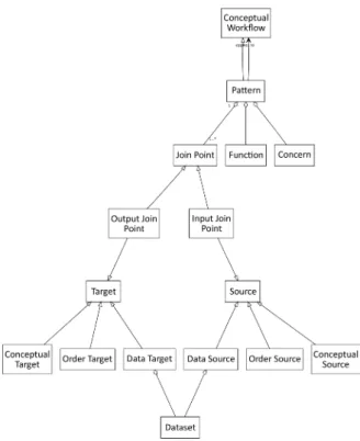
Patterns are themselves Conceptual Workflows, spe-cial in that they feature Join Points.
Join Points are placeholders in a Pattern that are re-placed with elements of the base process during application. A high-level Pattern is one that features only high-level elements, namely: Conceptual Inputs, Conceptual Work-flows, Conceptual Outputs and Conceptual Links. If a Pat-tern features low-level elements such as Activities and Data Links, then it is a low-level Pattern.
Figure 14: Meta-model - Patterns
Both levels of Patterns are shown on Figure 13 and the part of the meta-model concerning Patterns is described in UML3
on Figure 14 (default cardinality is * (many)). To apply a Pattern to a Conceptual Workflow means to merge the two by mapping each Join Point in the Pattern to a compatible element in the Conceptual Workflow. Each Join Point is connected to the rest of the Pattern it belongs to by at least one link and those links restrain compatibility: a Join Point must be replaced with an element that is com-patible with its links. For instance, if a given In Join Point is connected to the rest of the Pattern by a Data Link, then it is replaced by a Data Source; Conceptual Sources and Order Sources will not do. Table 1 details all cases.
4.2
Application to VIP use case
The Split/Merge concern, i.e. the optimization by split-ting data, can be implemented in very different ways, de-pending on the process it applies to as well as the activi-ties the process maps to. For instance, the main activity of the MRI simulator (SIMRI) (i.e. a legacy program called simri_calculwrapped as a Web service), uses MPI to pro-cess data chunks in parallel and thus already fulfills the Split/Mergeconcern. None of the other three simulators handle that concern internally.
Because it affects the very structure of a process, the pattern we defined to capture the Split/Merge concern is a high-level one. As shown on Figure 15, applying the Split/Mergepattern to a Conceptual Workflow boils down to weaving two additional steps into the process: a pre-processing step to split input and a post-pre-processing step to merge output. Both steps must then be mapped like any other Conceptual Workflow.
When a conceptual workflow has been mapped to two or more activities, weaving becomes less straightforward. There are two main cases (shown on Figure 16):
Figure 15: Pattern - Split/Merge
Figure 16: Split/Merge cases
• Case 1: data independence is valid throughout the processing chain and thus data is split only once at the very beginning and merged only once at the very end of the chain.
• Case 2: data independence is only valid at the scale of each activity and thus data must be merged after each processing step in the chain.
Any other case is a composite of those two and suggests that the conceptual workflow should itself be split or detailed through encapsulated sub-workflows.
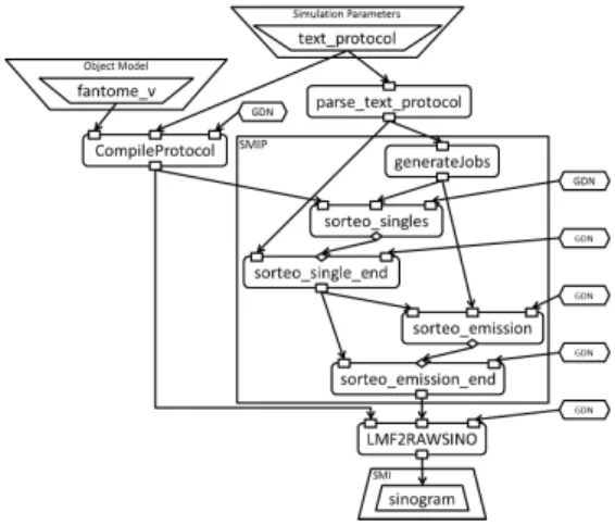
Figure 17: Sorteo - Mapping (with Patterns) Sorteo is an example of the Case 2, as shown on Figure 17, which is the result of Mapping Sorteo after applying the Split/MergePattern. The generateJobs activity appears twice, but it is fairly easy to determine that it is the same instance during the Composition phase.
Table 1: Compatibility between Links and Sources/Targets Abstraction Level Link type Source type Target type
High-level Conceptual Link Conceptual Source Conceptual Target Low-level Data Link Data Source Data Target
Order Link Order Source Order Target
Figure 18: Pattern - Directory Name
All simulators expect the name of the output directory. There is a naming convention sub-workflow that is respected throughout the platform and it is captured in a Pattern called Directory Name, shown on Figure 18.
Figure 19: Sorteo - Composition (with Patterns) Figure 19 shows the result of using the Directory Name pattern (abbreviated GDN on the figure) when composing Sorteo: the reuse itself becomes obvious and the overall read-ability is much improved.
5.
PROCESS SEMI-AUTOMATION
Conceptual Workflows allow scientists to model their in-silico experiments directly at the domain level, but the trans-formation process into executable Abstract Workflows im-plies lowering the abstraction level and using technical and non-functional knowledge and know-how.
The transformation process from Conceptual to Abstract workflow defined in Section 3 was performed manually in the case presented in Section 3.2, but our goal is to pro-vide tools for workflow designers to ease reuse, repurposing and ultimately sharing of Scientific Workflows. It is there-fore critical to assist end-users through the transformation process as much as possible.
5.1
Resources
To achieve our goal implies handling multi-domain knowl-edge in a computer-legible way. As elaborated in [8],
Se-mantic Web technologies were created and are developed
precisely to tackle that challenge.
An ontology is the formal definition of concepts and re-lationships between them. The standard language, recom-mended by the World Wide Web Consortium4
(W3C ), is the Web Ontology Language5
(OWL). Ontologies have two main uses: (1) to describe a domain in a formal and stan-dardized way (2) and to reason about entities (instances of the classes defined in the ontology) in order to infer new in-formation based on what has been asserted. For instance, if it is stated that :Man rdfs:subclassOf :Mortal (men are mortal) and it is asserted that :Socrates a :Man (Socrates is a man), then an inference engine can infer that :Socrates a :Mortal(Socrates is mortal).
The concepts the system will deal with can be divided into three classes: (i) domain concepts from the end-user scien-tific research area, (ii) technical concepts related to the ex-ecution of the experiment and (iii) non-functional concepts such as Quality of Service concepts. However, ontologies are not necessarily divided along those lines. For instance, in the context of the VIP project, the domain and technical concepts will come from the VIP ontology and we will build our own ontology dedicated to non-functional concerns.
The set of asserted information is generally called the
Knowledge Base. In our system’s case, it will be an actual database (called a Triple Store because it stores assertions
as Subject-Property-Object triples).
Specific elements of our Conceptual Workflow model act as a bridge to the ontologies:
• Functions are domain or technical concepts describ-ing processes and actions (e.g. GenerateSdescrib-ingles, Con-vertLMFtoRawSINO),
• Datasets are domain or technical concepts describing data types or contents (e.g. LungCancer, ZrawFormat) • and Concerns are non-functional concepts (e.g.
Spli-tAndMerge, Logging).
As detailed in Sections 2.1, 3.1 and 4.1, Conceptual Work-flows and Patterns are annotated with Functions and Con-cerns, Activities with Functions and Inputs/Outputs (of a Conceptual Workflow or of an Activity) with Datasets.
Ontologies and annotations form a graph whose vertices are entities and whose edges are properties; a triple is es-sentially an edge from a source vertex Subject to a target vertex Object, labeled by a Property. That graph is en-riched through inference. Browsing those often huge graphs is somewhat akin to browsing relational databases and the standard SPARQL Query Language for RDF6
is itself an
SQL look-alike. If we wanted to look for Conceptual
Work-flows that fulfill the SplitAndMerge concern, we would use a query that looks like Listing 1.
4 http://www.w3.org/ 5 http://www.w3.org/TR/owl-overview/ 6 http://www.w3.org/TR/rdf-sparql-query/
Listing 1: SPARQL query example SELECT ?cw WHERE { ?cw a : ConceptualWorkflow . ?cw : f u l f i l l s ? c o n c e r n . ? c o n c e r n a : SplitAndMerge . }
5.2
Towards automating transformation
At the start of the transformation process detailed in Sec-tion 3 and represented on Figure 5, we have the following in-formation and tools at hand: a high-level annotated Concep-tual Workflow that we want to transform, a Knowledge Base containing annotated Activities, Conceptual Workflows and Patterns as well as the ontologies the annotations refer to (i.e. theoretically, a domain ontology, a technical ontology and a non-functional ontology, though, as noted in the pre-vious section, the distribution of concepts over ontologies might differ in practice).
During the Mapping phase of the transformation pro-cess, our system should suggest Activities, Inputs and Out-puts matching the Functions, Datasets and Concerns that annotate the high-level Conceptual Workflow. Because per-fect matches are unlikely, the system will have to look for partial matches (called candidates) - that is easily done through a SPARQL query - and rank them according to
similarity metrics that take semantic distance (distance
be-tween concepts inside an ontology) into account. For in-stance, a :MonteCarloPETSimulator with outputs :LmfFor-matlike Sorteo is an imperfect but good match for a :PET-Simulatorthat outputs :RawSINOFormat.
During the Composition phase, our system should not only suggest composing elements found at the previous step, but also check every data link for consistency (and warn the user when a mismatch is found, like sending a String to a service expecting a File). When direct composition is not possible because of a mismatch, the system should try to look for converter activities or suitable chains of converter activities, up to a depth that does not impact performance too severely.
The Conversion phase, the final translation to a target Abstract Workflow language, ought to be fully automated. Each target language will warrant a dedicated translator. Our top priority is translation to the workflow language (GWENDIA) of the framework used on the VIP platform (MOTEUR), but we plan to work on other translators as well, especially one to IWIR (Interoperable Workflow
Inter-mediate Representation), the multi-platform language of the SHIWA7
interoperability project.
GWENDIA is a hybrid workflow language (mostly data-driven but featuring control constructs such as loops, condi-tionals and order constraints) that handles data arrays ex-plicitly [14]. Since GWENDIA is so expressive and our final workflow representation (i.e. the result of the Composition phase) is fairly close to it, the conversion will be straightfor-ward but for a few advanced constructs that require further investigation.
7
http://www.shiwa-workflow.eu/
5.3
Limitations
Between the Concrete level of execution, where the Enac-tor handles strings, files and Web services, and the Concep-tual level of the user’s domain, where semantics are formally defined by ontologies, there is always a gap of description where knowledge is present only implicitly. Try as we might, we will never completely fill that gap, neither by extend-ing ontologies to ever finer-grained concepts (e.g. extendextend-ing :ImageFilewith :PNGFile), nor by extending the basic for-mats with higher-level information (e.g. tagging additional information inside the files).
From that gap will come false positives, where the com-position of two activities will seem possible to the system, because they match at both the low level of types and the high level of concepts, but will not work for some unforeseen and/or out-of-scope reason.
Besides, annotations will likely be imperfect themselves and that entails false negatives: good candidates that will rank low or not be found at all, because either they them-selves or the Conceptual Workflow they could be suggested for were not annotated properly.
For all those reasons, the transformation process can never be fully automated. Still, the more computer-aided it be-comes, the better.
6.
RELATED WORKS
Our approach is very similar to that of the Wings [?] project, but their aim is to build a self-contained solution on top of the Pegasus8
framework. While we see the benefits of a single unified system from high-level in-silico experi-ments all the way down to computing infrastructures, we hope that by defining our model upstream from all exist-ing frameworks, it will be of use for users of existexist-ing sys-tems and potentially become a basis of comparison between frameworks.
The well-knownmyExperiment project [5] is a Scientific
Workflow sharing social website, leveraging the Web 2.0 to ease workflow discovery. Workflows can be discovered by keywords, tags, authors and so on, but all those methods, save for pure social sharing, rely on additional metadata provided by the workflow authors. As for the reuse as-pect of sharing, the myGrid team, behind Taverna as well
as myExperiment, advocates for “semantically rich
aggre-gations of resources, that possess some scientific intent or support some research objective” [?]: a definition we believe
our Conceptual Workflows fit.
The WOODSS project [13], like our proposal, enhances reuse and sharing through the creation of knowledge base of annotated Scientific Workflows, but they provide no formal high-level description like Conceptual Workflows.
The Kepler Project [11] has always considered Separa-tion of Concerns a top priority, going as far as isolating the
Model of Computation (i.e. the exact same workflow can
be executed in entirely different ways depending on which
Director is selected, for instance in sequence or in
paral-lel). Among works to improve reuse of Kepler workflows are [4], which introduces a separated control-driven layer in the data-driven Kepler, and [1], which captures technical and non-functional concerns as coarse-grained composable blocks. In both cases, the user is further shielded from the concrete technical decisions taken at runtime and, in the
8
latter, Semantic Web technologies are also considered a vi-able tool to semi-automate instantiation (i.e. mapping) and wiring (i.e. composition). In neither case is the in-silico experiment formally represented at all.
7.
CONCLUSION AND FUTURE WORKS
We have defined Conceptual Workflows and shown how they can be used to untangle concerns and improve read-ability, by emphasizing the scientific process itself, and thus ease reuse and repurposing. That formal model (including low-level elements akin to those found in Abstract Work-flows), semantic annotations and a SPARQL query engine make it possible to semi-automate the transformation from an in-silico experiment (described as a high-level Conceptual Workflow) to an executable artifact (in an Abstract Work-flow language).
In the future, we plan to investigate how much our Con-ceptual Workflow model and the system we are building on top of it can become useful not only for reuse and repurpos-ing, but also for portability - using Conceptual Workflow as a go-between two different target Abstract Workflow lan-guages - and to improve accessibility for end-users - through the improved readability and support of know-how transfer via computer-aided design.
8.
ACKNOWLEDGMENTS
This work is funded by the French National Agency for Research under grant ANR-09-COSI-03 “VIP” and the Eu-ropean I3 SHIWA project under contract number 261585. The UML diagrams of Figures 3, 7 and 14 were generated with the great free online engine provided by Tobin Harris at http://yuml.me.
9.
REFERENCES
[1] I. Altintas, A. Birnbaum, K. Baldridge, W. Sudholt, M. Miller, C. Amoreira, Y. Potier, and B. Lud¨ascher. A Framework for the Design and Reuse of Grid Workflows. In Scientific Applications of Grid
Computing, volume 3458 of LNCS, pages 295–299.
Springer, 2005.
[2] R. Barga and D. Gannon. Scientific versus Business Workflows. In Workflows for e-Science, chapter 2, pages 9–16. Springer-Verlag, 2007.
[3] H. Benoit-Cattin, G. Collewet, B. Belaroussi,
H. Saint-Jalmes, and C. Odet. The SIMRI project : a versatile and interactive MRI simulator. Journal of
Magnetic Resonance Imaging (JMRI), 173(1):97–115,
Mar. 2005.
[4] S. Bowers, B. Lud¨ascher, A. Ngu, and T. Critchlow. Enabling Scientific Workflow Reuse through Structured Composition of Dataflow and
Control-Flow. In IEEE Workshop on Workflow and
Data Flow for Scientific Applications (SciFlow),
Atlanta, USA, Apr. 2006.
[5] D. De Roure, C. Goble, and R. Stevens. The Design and Realisation of the myExperiment Virtual Research Environment for Social Sharing of Workflows. Future Generation Computer Systems
(FGCS), 25(5):489–598, 2009.
[6] W. Frakes and K. Kyo. Software reuse research: status and future. IEEE Transactions on Software
Engineering (TSE), 31(7):529–536, July 2005.
[7] Y. Gil, E. Deelman, M. Ellisman, T. Fahringer, G. Fox, D. Gannon, C. Goble, M. Livny, L. Moreau, and J. Myers. Examining the Challenges of Scientific Workflows. Computer, 40(12):24–32, 2007.
[8] A. Goderis, U. Sattler, P. Lord, and C. Goble. Seven Bottlenecks to Workflow Reuse and Repurposing. In
The Semantic Web – ISWC 2005, volume 3729 of LNCS, pages 323–337. Springer, Heidelberg, Germany,
2005.
[9] D. Hull, K. Wolstencroft, R. Stevens, C. Goble, M. R. Pocock, P. Li, and T. Oinn. Taverna: a tool for building and running workflows of services. Nuclear
Instruments and Methods in Physics Research A,
34(7):729–732, July 2006.
[10] J. Jensen. Simulation of advanced ultrasound systems using Field II. In IEEE International Symposium on
Biomedial Imaging: Nano to Macro, pages 636–639,
Arlington, VA, USA, Apr. 2004.
[11] B. Lud¨ascher, I. Altintas, C. Berkley, D. Higgins, E. Jaeger, M. Jones, E. A. Lee, J. Tao, and Y. Zhao. Scientific Workflow Management and the Kepler System. Concurrency and Computation: Practice &
Experience (CCPE), 18(10):1039 – 1065, Aug. 2006.
[12] T. McPhillips, S. Bowers, D. Zinn, and B. Lud¨ascher. Scientific workflow design for mere mortals. Future
Generation Computer Systems (FGCS),
25(5):541–551, 2009.
[13] C. B. Medeiros, J. Perez-Alcazar, L. Digiampietri, G. Z. J. Pastorello, A. Santanche, R. S. Torres, E. Madeira, and E. Bacarin. WOODSS and the Web: annotating and reusing scientific workflows. SIGMOD
Record, 34(3):18–23, Sept. 2005.
[14] J. Montagnat, B. Isnard, T. Glatard, K. Maheshwari, and M. Blay-Fornarino. A data-driven workflow language for grids based on array programming principles. In Workshop on Workflows in Support of
Large-Scale Science (WORKS’09), pages 1–10,
Portland, USA, Nov. 2009. ACM.
[15] A. Reilhac, C. Lartizien, N. Costes, S. Sans, C. Comtat, R. N. Gunn, and A. C. Evans.
PET-SORTEO: a Monte Carlo-based Simulator with high count rate capabilities. IEEE Transactions on
Nuclear Science (TNS), 51(1):46–52, Feb. 2004.
[16] J. Tabary, S. Marache, S. Valette, W. Segars, and C. Lartizien. Realistic X-Ray CT Simulation of the XCAT Phantom with SINDBAD. In IEEE NSS and
MIC Conference, pages 3980–3983, Orlando, USA,
Oct. 2009.
[17] J. Yu and R. Buyya. A taxonomy of scientific workflow systems for grid computing. ACM SIGMOD